Note: Descriptions are shown in the official language in which they were submitted.
2 ~ 2 ,~
Case 77
"COMPACTION APPARATUS AND
METHOD FOR COMPACTING SAND"
BACKGROUND OF THE INVENTION
1. Field of the Invention
The present invention is generally related to
compaction apparatus and processes and, more particularly,
to a compaction apparatus and process for compacting sand
in a flask about a pattern.
2. Background Art
There are many industrial applications utilizing
granular materials, such as sand. One parti~ularly
noteworthy application is a foundry which performs the
process of casting metals, e.g., by making sand molds for
casting. In casting processes, a mold is made by packing
molding sand around a pattern.
~ecause the sand must be tightly compacted around the
pattern, sand migration must be facilitated. This is
especially true in the case of complicated pattern
configurations such as those that are available in modern
casting processes. However, compaction systems have
generally not provided the desired degree of sand migration
Qr sand pressure.
The present invention is directed to overcoming the
above stated problems and accomplishing the stated objects
by providing a uniqùe compaction apparatus and process for
compacting sand.
SUMMARY OF THE INVENTION
Accordingly, the present invention is directed to a
compaction apparatus comprising a flask adapted to contain
sand. Means are provided for resiliently supporting the
flask in a vertical orientation, as well as means for
`; imparting vibrational forces to the flask. In particular,
~30 the vibrational forces have bo~h horizontal force
~` :
Case 77
- 2 ~
components and vertical force components. ~ -
Specifically, the horizontal force components cause ~ ~
generally horizontal oscillating movement of the flask. It -~ ;
is also a feature of the invention that the vertical force
components are alternating oppositely directed forces which
establish a force couple and maintain the flask in a `~;~
controlled orientation during the generally horizontal
oscillating movement thereof, particularly at the limits of
travel where flask movement changes direction. In this
connection, the force couple is adapted to counteract the
rotational inertia of the sand-filled flask.
In an exemplary embodiment, the force imparting means
includes a vibrator motor having a vibrator shaft and a
plurality of additional vibrator shafts operatively
associated with the vibrator motor shaft. The vibrator
motor shaft and the additional vibrator shafts aach include ~ ~ ;
force producing and rotational inertia counteracting means
associated therewith. Preferably, the vibrator motor w~th
its vibrator shaft as well as the additional vibrator
shafts are all rigidly mounted to a table which supports
~; the flask in the vertical orientation. ~ ;
In the preferred embodiment, the force producing and
rotational inertia counteracting means includes an ;~ 2
eccentrically mounted weight on the vibrator motor shaft
and~eachi!ofl the add!itiionali vibrator shafts. The vibrato!r
motor shaft and the additional vibrators shafts are all
mounted on parallel axes extending generally perpendicular
to the direction of generally horizontal oscillating
movement of the flask. Also, two of the four parallel
30~ vibrator s~afts are positioned and arranged so as to rotate
in opposite directions about their respective parallel axes
`~ ~ in a generally vertical plane in which the center of
gravity of the flask, pattern and sand are disposed. `~
In this connection, the vertically coplanar vibrator
,:
- .:
. '. ~: ',
case 77 ~
-- 3 -- ~ :
~ .
shafts are preferably arranged such that their respective
eccentrically mounted weights together produce a horizontal
force component first in one direction and then in the
opposite direction during one hundred eighty degrees of
rotation thereof. Still more specifically, the vertically
coplanar vibrator shafts are also preferably arranged such
that their respective eccentrically mounted weights
together produce equal but opposite vertical force
components that cancel one another at every point
throughout three hundred sixty degrees of rotation thereof.
With this arrangement, a pair of the vibrator shafts
are also advantageously provided on opposite sides of the
one of the vibrator shafts in the generally vertical plane
in which the center of gravity of the flask, pattern and
sand are disposed. Advantageously, this pair of vibrator
shafts is arranged such that the eccentrically mounted
weights thereon each always produce equal but opposite
vertical force components on opposite sides of the
generally vertical plane first in one direction and then in
the opposite direction during one hundred eighty degrees of
rotation thereo~. Preferably, the vertical force
components establishing the force couple include a
vertically downward force component on the leading edge of
the flask and a vertically upward force component on the
trailing edge of the flask
In a modification to the exemplary embodiment, the
vibrator motor may be mounted externally to the compaction
apparatus and may drive the force imparting means
¢omprising the four parallel shafts by means of a belt
drive mechanism.
In addition, the present invention is directed to a
process for compacting sand in a flask, including the step
~; of resiliently supporting the f~ask in a vertical
orientation. The process further includes the step of
'` ~ . '
.. .. .. . .. ... ....... ... -
Case 77
- 4 -
imparting vibrational forces to the flask having horizontal
and vertical force components such that the horizontal
force components cause generally horizontal oscillating
movement of the flask and the vertical force components
establish a force couple which comprises alternating
oppositely directed force components for maintaining the
flask in a controlled orientation during the generally
horizontal oscillating movement thereof. In accordance
with the process, the force couple is directed to
coun~eract the rotational inertia of the flask, pattern and
sand.
In another aspect of the present invention, the force
couple established by the alternating oppositely directed
vertical force components may be prescribed by means of the
eccentric weights, specifically, the eccentric weights are
such that alternating oppositely directed vertical force
components serve to maintain the flask in a vertical
orientation during the generally horizontal oscillating
movement thereof, particularly at the limits of travel
where horizontal flask movement changes direction. In
other words, the force couple produced by the eccentric
weights is adapted to balance the rotational inertia of the
sand-filled flask.
Other objects, advantages and features of the present
invention will be apparent from a consideration of the
following specification taken in conjunction with the
accompanying drawings.
BRIEF DESCRIPTION QF THE DRAWINGS
FIGURE 1 is a front elevation view, partially
~30 schematic, illustrating the compacting apparatus of the
present invention approaching the limit of travel in one
direction;
~ . .. , :
FIGURE 2 is a front elevat~onal view, partially
schematic, illustrating the compacting apparatus at a first
~-:, : ~ . ...
~. ...
u~.
Case 77 ;;;~
5 - ,- -
midstroke position;
FIGURE 3 is a front elevational view, partially
schematic, illustrating the compacting apparatus of the
present invention approaching the limit of travel in the
opposite direction, and
FIGURE 4 is a front elevational view, partially
schematic, illustrating the compacting apparatus at a
second midstroke position.
DETAILED DESCRIPTION OF THE PREFERRED EMBODIMENT
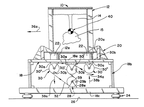
Referring to the drawings, and first to Figure 1, the
reference numeral 10 designates generally a compaction
apparatus in accordance with the present invention. The
compaction apparatus 10 includes a flask 12 resiliently
supported in a vertical orientation to contain sand 14 and
a pattern 15.
Still referring to Figure 1, a table 18 supports the - ;
flask 12 in the vertical orientation and conventional clamp
means 20 releasably secures the flask 12 to the table 18. -
The clamp means 20 may be of a hydraulically actuated type
commonly known to those skilled in the art. Clamp means 20
are distributed about the table 18 and include radially
` inwardly projecting fingers 20a adapted to engage a flange
I2a or the flask 12.
In the preferred embodiment, the compaction apparatus
10 includes a plurality of resilient flask supports 22 ;
which serve to resiliently support the flask 12 above the
table 18. Thus, the inwardly projecting fingers 20a of the ;~
clamp means 20 engage the flange 12a to hold the flask 12
firmly in engagement with the resilient flask supports 22.
In addition, the compaction apparatus 10 includes a
pIurality of resilient table supports 24 which serve to
resiliently support the table 18 above a supporting surface
26.
As will be appreciated, the table 18 preferably
case 77
- 6 -
includes a generally horizontal platform portion 18a to
which the clamp means 20 and resilient flask supports 22
are secured. It will also be seen that the table 18
includes a plurality of resilient stabilizer members 18b
depending therefrom and secured to a generally horizontal
base 18c which is spaced from the platform portion 18a by
means of the resilient stabilizer members 18b and spaced
from the supporting surface 26 by means of the resilient
table supports 24. With this arrangement, the resilient
table supports 24 can take the form of airbags or springs
secured to the underside of the base 18c to maintain it in
spaced relation to the supporting surface 26.
As shown in Figure 1, means are provided for imparting
vibrational forces to the flask 12, including a vibrator
motor 28 having a vibrator shaft 29 and a plurality of
independent vibrator shafts 30. It will be appreciated
that the independent vibrator shafts 30 are operatively
associated with the shaft 29 of the vibrator motor 28 as
through a timing belt 32, as will be discussed in greater
detail hereinafter. While shown only schematically, it
will be appreciated that the vibrator motor 28, with its
shaft 29, is mounted on the base 18c by shaft supports 28a
and vibrator shafts 30 are rigidly mounted to the table 18a
on shaft supports 28a and 30a to impart vibrational forces
from the shafts to the~table~18.
More specifically, the vibrator motor 28, with its
shafts 29 and the other three vibrator shafts 30, imparts
vibrational forces having horizontal force components, as
represented by the arrows 34a (Fig. 1) and 34b (Fig. 3).
~30 This causes generally horizontal oscillating movement of
the flask 12, as represented by the arrows 36a (Fig. 1) and
36b (Fig. 3). It will further be seen that the vibrational
~` forces include alternating oppositely directed vertical
force components, as represented by the arrows 38a and 38b.
~:
Case 77
i,
~ - .
This establishes a force couple which maintains the flask
12 in a controlled orientation during the generally
horizontal oscillating movement thereof. By means of the
alternating oppositely directed vertical force components
38a and 38b, it is possible to counteract rotational
inertia of the flask 12 in order to maintain its generally
controlled orientation.
As will be appreciated by referring to Figures 1 and
3, the force couple comprises a vertically downward force
component 38a acting on the leading edge of the flask 12
and a vertically upward force component 38b acting on the
trailing edge of the flask 12 at least at the limits of
travel during the generally horizontal oscillating movement
of the flask 12. By now referring to Figures 2 and 4, it
will be appreciated that the vertically downward force
component 38a acting on the leading edge of the flask 12
and the vertically upward force component 38b acting on the
trailing edge of the flask 12 are zero at the midway point
between the limits of travel during the generally
horizontal oscillating movement of the flask 12.
As shown in the drawings, the vibrator motor 28, with
its vibrator shaft 29 and the other three independent
vibrator shafts 30, each include force producing and
rotational inertia balancing means associated therewith.
~25 More~ specifically~ "the force producing and rotational
~` inertia balancing means includes eccentrically mounted
weights 29b and 30b, respectively, on each of the vibrator
motor shaft 29 and the independent vibrator shafts 30.
With this arrangement, the vibrator motor shaft 29 and the
~30 vibrator shafts 30 are suitably mounted on parallel axes
extending perpendicular to the direction of oscillating
movement of the flask 12.
Still more specifically, the v~brator motor shaft 29
~ and one of the independent vibrator shafts 30' are mounted
; ~
~: :
,~, . .
I
s ::
Case 77
- 8 -
so as to rotate in opposite directions about their
respective parallel axes in a generally vertical plane in
which the center of gravity, as at 40, of the flask 12,
pattern 15 and sand 14 are disposed. The vertically
coplanar vibrator motor 28 and vibrator shaft 30' are also
arranged, as will be appreciated by referring to Figures 1
and 3, such that their respective eccentrically mounted
weights 28b and 30b together produce the horizontal force
components 34a and 34b first in one direction and then in
the opposite direction during a one hundred eighty degree
rotation of the vibrator motor shaft 29 and the vibrator
shaft 30'. As will also be appreciated, the vibrator motor
shaft 29 and the vibrator shaft 30' are arranged such that
their respective eccentrically mounted weights 28b and 30b
together produce equal but opposite vertical force
components that cancel one another at every point during
three hundred sixty degrees of rotation thereof. ;~`
By comparing Figures 1 through 4, it will be
appreciated that a pair of the vibrator shafts 30'' and
30 " ' are disposed at opposite sides of the vibrator shaft
30'. The timing belt 32, which may, by way of example, be ~ ;
a belt having double teeth along its length for nonslip
drive, serves to ~oin all of the vibrator shafts 30', 30 "
; and 30 " ' to the vibrator motor shaft 29 for driven
moyement thereky. ~By reason o~f the winding of the timin~
balt 32, the vibrator motor shaft 29 and vibrator shafts
~ 30 " and 30 " ' rotate in the same direction about the
``~; pàrallel axes thereof. ~
By reason of the placement of the eccentrically ;
. 30 mounted weights 30b on the vibrator shafts 30 " and 30 "',
the vertically downward force component 38a is applied
f1rst by the vibrator shaft 30 " and then by the vibrator
shaft 30 " ' during a one hundred eighty degree rotation of
the vibrator shafts 30 " and 30 "'. Similarly, the
:'~' ;' :
~ ` 2~2~
:::
Case 77
_ 9 _
vertically upward force component 38b is provided first by ~ -~
the vibrator shaft 30 " ' and then by the vibrator shaft
30 " during the same one hundred eighty degree rotation of
the vibrator shafts 30 " and 30 " '. Thus, due to the
relationship of the vibrator shafts 30 " and 30 "', the
vertical force components are always oppositely directed
and cyclically alternating, i.e., alternate between a
vertically downward force component 38a and a vertically
upward force component 38b during each one hundred eighty
degree rotation.
As will be appreciated, the eccentrically mounted
weights 30b on the vibrator shafts 30 " and 30 " ' produce
no vertical force component at the midpoint of travel (see
Figures 2 and 4~. There is also no horizontal force
component at this position by reason of the placement of
the eccentrically mounted weights 29b and 30b on the
vibrator motor shaft 29 and the vibrator shaft 30' inasmuch
as these midstroke positions are where the compaction
apparatus 10 is shifting from producing the horizontal
force component 34a to cause generally horizontal '` ii' .
oscillating movement first in one direction, as represented
by the arrow 36a, to producing the horizontal force
component 34b to cause generally oscillating movement next
in the opposite direction, as represented by the arrow 36b.
In addition, the position, of the eccentrica~lly mounted `
;~ weights 29b on the vibrator motor shaft 29 and 39b on the
vibrator shaft 30' cause the vertical force components to - -
cancel at every position, including the midstroke
positions, as shown in Figures 2 and 4.
~` 30~ It should be understood that the vibrator motor 28 may
be positioned such that the vibrator motor shaft 29 assumes
the position of any of the four parallel vibrator shafts of
the preferred embodiment. In a .modification of the
preferred embodiment, the motor may be mounted to the
~,
.-: .
~''.,".. ,.'"',.,",.. ,,',.. ,,'',,,'".'.,.,.. '".,.,','`i ;,
Case 77 i ~ ~
- 10 ~
platform 18a on its shaft supports 28a, with a vibrator
shaft such as 29 positioned as shown in the drawings and
the independent vibrator shafts 30 and respective eccentric
weights 2sb and 30b also positioned as shown so as to ~ s~
achieve a force imparting means identical to that of the
preferred embodiment. It should be further appreciated
that the vibrator motor 28 could be mounted externally to ~ h
the compaction apparatus 10 and connected through a belt
drive such as 32 to any of a plurality of independent
parallel vibrator shafts 29 and/or 30. Similarly, the
vibrator motor 28 may be arbitrarily mounted to the
platform 18a or base 18c on its shaft supports 28a and
connected through a belt drive to any of a plurality of
independent parallel vibrator shafts 29 and/or 30.
~;~15 In accordance with the invention, a process for
compacting sand about a pattern in a flask has been
provided which includes the step of resiliently supporting `z~
the flask in a vertical orientation. The process further
~ includes the step of imparting vibrational forces to the ~;
;~ 20 flask having both horizontal and vertical force components
wherein the horizontal force components cause generally
; horizontal oscillating movement of the flask and the
vertical force components comprise alternating oppositely
directed vertical force components for maintaining the --~
flask in a controlled qrientation or orientations, during ; ;~
the generally horizontal oscillating movement thereof.
With this unique arrangement of forces, and in accordance
` ~ with the process, a force couple is directed so as to ~;
counteract the rotational inertia of the flask. ;;
More specifically, the vibrational force imparting `~ ~
step produces the horizontal force components first in one ~ ~ -
direction and then in the opposite direction to cause the
generally horizontal oscillating mo,vement of the flask.
~;~ The horizontal force components are produced in a generally
.. .
~7.,~3~ ~'
. . ,
-- .
Case 77
.
vertical plane extending through the center of gravity of
the flask and sand. Moreover, the vibrational force
imparting step produces no resultant vertical force
component in the generally vertical plane extending through
the center of gravity of the flask, pattern and sand.
Additionally, the vibrational force imparting step
produces a force couple comprising the alternating
oppositely directed vertical components on opposite sides
of the generally vertical plane extending through the
center of gravity of the flask and sand. The force couple
is produced first in one direction and then in the opposite
direction in order to counteract the rotational inertia
during the generally horizontal oscillating movement of the
flask. In this connection, the vertical force components
include a vertically downward force component on the
-~ leading edge of the flask and a vertically upward force
component on the trailing edge of the flask at the limits
of travel thereof.
With the compaction apparatus 10 illustrated in the
~20 drawings, the vibrator motor shaft 29 and the vibrator
shaft 30' produce the primary horizontal force. This, in
turn, causes the flask 12 to undergo the generally
horizontal oscillating movement which is well suited for
compacting the sand 14 tightly around the pattern 15 within
the flask 12. At the sameitime, the vibrator~shafts 30 "
and 30 " ' produce the vertical force components, i.e.,
-~ countertor~ae forces, to counteract "tipping" forces from
the rotational inertia of the flask 12
As will be appreciated by referring to Figures 1
through 4, the eccentrically mounted weights 30b on the
vibrator shafts 30 " and 30' " are always out of phase one
-~ hundred eighty degrees. Thus, when they are at their
vertical extremes, as illustrated in~Figures 1 and 3, they
produce the vertical force components 38a and 38b, whereas,
.~
~:
,
h f~
~;
Case 77
,: :
when they are at their horizontal extremes, they produce no
vertical force components and cancel horizontal force
components. As a practical matter, the vertical force
components will increase from zero to a maximum as the
eccentrically mounted weights 30b move from their
horizontal extremes to their vertical extremes.
With regard to the eccentrically mounted weights 29b
and 30b on the vibrator motor shaft 29 and vibrator shaft
~ 30', they produce the horizontal force components 34a and
34b at their horizontal extremes. As the eccentrically
mounted weights move toward their vertical extremes, as
illustrated in Figures 2 and 4, the horizontal force ~ ~`
components change from a maximum value to zero. Also,
I because of the opposite rotation of the vibrator motor
shaft 29 and the vibrator shaft 30', the eccentrically
mounted weights 28b and 30b always produce vertical force
~-~ components that cancel.
While in the foregoing there has been set forth a
preferred embodiment of the invention, it will be i`~
appreciated that the details herein given may be varied by
~1 those skilled in the art without departing from the spirit
and scope of the appended claims.
. ' .
~: ' ;' ' ' I ' I ' ' ' ' "
I ~-
:
.. ,;
' ' `''''