Note: Descriptions are shown in the official language in which they were submitted.
The present invention relates to an automatic toll
exaction system for urban and extraurban highways, for
bridge and tunnel crossings and for accesses to urban areas
and car parks.
As is known, through the years, ln view of the fact
that the highway system has a strategic role of development
and integration of the territory, an extensive integrated
networ~ capable of providing the necessary assurances of
ease of transit as well as new services related to stops and
; lo to increasingly complete tourist-cultural information and
information on road conditions has been developed. In
particular, in order to increase fluidity, safety and
comfort on the highway network, and in order to reduce the
congestion of traffic near stations, which is endured by
15 highway users with rising intolerance, there has been a
constant commitment aimed at the adaptation of the
structures and to the development of automation. A further
fluidizing factor is constitu~ed by the possibility of
paying the toll by means of electronic money in the two
20 forms with a "prepaid charge-deduction" card or with
eharying either di.rectly or by means of contracted
organizations or finally with charging to a bank account
(VIACARD system).
However, the neecl for further improvement in
25 transportation and fluicdity on the main multimodal lanes and
for adaptation of aecesses to metropolitan areas is felt.
$ ~
Consequently, the aim of the present invention is to
provide an automatic toll exaction system for urban and
extraurban hi~hways, for bridge and tunnel crossings and for
accesses to urban areas and car parks which can satisfy
5 these requirements of improvement in transportation bv means
of the dynamic exaction of the toll.
Within the scope of this aim, a particular object of
the present invention is to provide an automatic toll
: exaction system which can:
- simultaneously provide the diffusion of precise and
timely information on road conditions and on the services
offered;
- ensure greater fluidity, safety, reduction of
pollution near stations and energy saving, since the vehicle
: 15 no longer needs to stop in the lane but can pass at the
~: speed enforced by safet~ regulations,
- have grPat reliabilitv and modularity to ensure the
progressive introduction of the various provided ser~rices
and the easy implementation of the new ones;
: 2~ - be easily integrated in the existing structures, as
regards both the vehicles and the road, and in particular
the configuration of the stations.
The system according to the invention must furthermore
be compatible and interactive with currentl~ installed
25 exaction syStemS, allow to maintain the currently existing
monetics circuit~ and allow opening to integration with
information processing systems.
This aim, the objects mentioned and others which will
become apparent hereinaEter are achieved by a toll exaction
:
4 ~2~
system for urban ~nd extraurban highwavs, for bridge and
tunnel crossings and for accesses to urban areas and car
parks, as defined in the accompanying claims.
The characteristics and advanta~es of the invention
5 will become apparent from the description of a preferred
~- embodiment, illustrated onlv by wa~ of non-limitative
e~ample in the accompanying drawings, wherein:
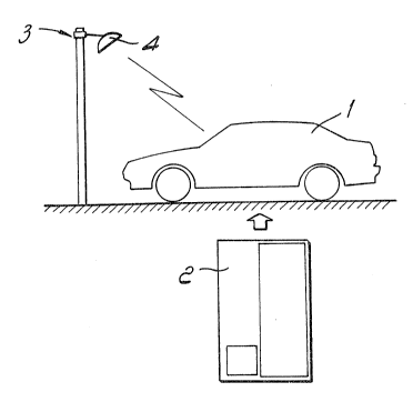
figure 1 is a schematic view of the three essential
; components of the system according to the invention;
lo figure 2 is a bloc~ diagram of the onboard apparatus;
figure 3 is a schematic view of the confi~uration of a
station executed according to the invention, illustrating
the division of the areas affected by the system;
figure 4 is a block diagram of the ground-based
15 apparatus; and
figures 5-8 are bloc~ diagrams of the steps for
automatic toll exactlon according to the invention.
With reference to figure 1, the system according to the
invention is substantially composed of three parts, and
20 precisely an onboard apparatus ~composed of the units shown
in figure 2~ mounted inside a motor vehicle 1 in a position
which can be accessed by the driver, a personal card 2,
which must be inserted in the onboard apparatus in order to
use the toll exaction system accordin~ to the invention, and
25 a ground-based apparatus (represented in figure 1 by a buoy
3 on which an antenna 4 is mounted and schematically
indicated in figure 4) which ensures linkup wlth the onboard
apparatus and the processing of the data for toll exaction.
.. ., . ., ..,. ,... .. ,. . ~
, . ~ ~ , . .
This ground-based apparatus also allows connection to the
existing information-processing and automation units.
The onboard apparatus has the function of ensuring the
reception and transmission of the messages, the handling and
5 storage of the transactions and the interaction with the
user ~generally the driver). In detail, said apparatus (see
figure 2) comprises a ground-to-vehicle radio-lin~ section
(composed of an antenna 5 and of a reception and
transmission device 6 of a known type), an information
10 processing section (composed of a control unit 7 with a
memory 8 of its own), a section for reading and encoding the
card (card reader 9) and a man-machine interface 10 which is
typically constituted by a display unit, which includes a
red LED and a green LED for displaying messages sent by the
15 ground-based apparatus or generated ~v the control unit 7,
and by a two-tone acoustic alarm system for attracting the
user's attention and repeating the visual indication
provided by the LEDs. A third yellow LED can furthermore be
provided; when lit, said L~D indicates that the card can no
20 longer be removed from the reader. Finally, means suitable
for allowing the user to receive further information
concernin~ road conditions and traffic may be provided. ~aid
means may be constituted for example by displays and/or
loudspea~ers or other solutions suitable for the purpose, as
25 well as by elements for connection to the devices which are
already available on board (radio, etc.).
The personal card, which for example can be executed as
an extension of the VIACARD (Trade Mar~) cards, has the
function of activating the onboard apparatus, of identifying
30 the user and of storing the operative data (such as the
operativitv or loc~ing of the card as well as the
transactions for the payment of the toll or of other goods
or services). Conveniently, in order to ensure that the
dialogue is confidential, to protect access to the system
and store the operative data, said card is executsd
according to the technology of microprocessor-equipped cards
which also contain electrically rewritable memories. The
card furthermore conveniently has, on the same support,
~magnetic tracks recorded according ~o the currently
;~lo applicable codings to allo~ the use of the same card (which
is removable from the onboard apparatus) even with
conventional station apparatuses for automatic toll exaction
and with those being installed for the payment of fuels and
refreshments.
As will be explained in greater detail hereinafter,
once the card is inserted in the onboard apparatus, it is
checked upon enterlng the highwa~: and stores the
characteristic da~a in replacement of the ticket for the
completion of the exit transaction. It furthermore stores
each individual transaction supportin~ each charge, thus
constituting a memorandum of the trips made for the user,
contains the restrictions of use (limit differentiated by
service and in time) and also verifies and stores the
occurrence of the enabling on the part of the system to the
fruition of the service by means of checks on a blacklist or
"white list", according to the preset procedures.
The yround-based apparatus, as already mentioned, has
the function of communicating with the onboard one for the
exchange of the data and messages required to ensure the
dynamic exaction of the toll and the transmission of ~eneral
' -
'
information on road conditions and traffic, as well as of
performing the necessary processing of the data. In
particular, two different transmission modes, which are
simultaneouslv present with automatic passage from one to
5 the other, are provided according to the content of the
messages. The first mode is aimed at a single user for the
; dynamic exaction of the toll by means of a selective linkup
(in particular with the identification and classification of
the vehicle and with the association thereof with the card
~; 10 inserted in the onboard apparatus). This entails the need to
locate the vehicle and to maintain a one-to-one
correspondence between the physical parameters detected by
means of the ground-based instruments and the user
- identification data gathered by radio. The second
15 transmission mode is aimed at many users (circular
transmission) for the broadcasting of news of general
interest, such as the state of the roads or the availability
; of services. In particular, in this case, the ground-based
apparatus allows to send information on road conditions, on
20 the presence of road yards, traffic blocks and detours, on
travel times, recommended alternate paths, availability of
services and weather conditions, and on the presence of
personal messages at the nearest service station. This
system, in a simpler configuration, allows to carry this
25 information along the hi~hway and possibly, by means of
appropriate installations, even along the ordinary road
system.
Consequently, each individual station executed
according to the present automatic exaction system has the
30 structure shown in figure 3. In said figure, khe reference
. . ''' '' ' ' ' ' '" ' ''' ~ ' ' ' ' ,
;-
-
.. .
2 ~
numerals 16 indicate two portions of highway which can be
followed in the outgoing direction (typically they represent
the two junction roads with the carriageways or lanes of the
highway), 17 indicates the portion after the toll station
5 which can be followed in the ingoing clirection toward the
actual highway, 18 represents a road (e.g. a provincial
road) which is linked to the highway by means of the
portions 16 and 17, and 19 indicates the station. The
station, according to the invention, comprises a plurality
lo of areas in which the messages necessarv for automatic
exaction are exchanged. In detail, three areas are p:rovided
and correspond to three logic steps which are repeated both
in entrv and in exit in case of a closed highway system:
a) a first approach step, during which the ground-based
15 system broadcasts circular sisnals to communicate the
availability of the sarvice and activate the onboard
apparatus which, passiny from a listening state to an active
one, performs all the auto-diagnostics chec~s and the card
functionality checks. The positive outcome of these checks,
~o which is notified to the user, authorizes said user to
continue toward the gate enabled for the tele-toll service;
otherwise an alarm indication requests him to move toward
another gate with manual or automatic exaction. This step is
performed in the areas indicated by AREA lE (for entering
25 the hi~hway) and AREA lU (for leaving said highway). I'he
areas lE and lU are chosen so that in this step the vehicle
is normally not routed, and the radioelectric coverage is
extended enough to ensure lin~up with all the passing
vehicles which are potentially interested in the message. In
30 this region, transmission is of the one-way type, from the
. ... , ", . . ,.. .. ~ . _ .. . .. .. . . .. ... ...... .. . ........... . .
, ' ' ' ~ :
9 2~
ground to the vehicle.
b) a second presentation step, during which the onboard
apparatus communicates the user`s identification data while
the ground-based apparatuses determine the class of the
vehicle for the application of the toll fare. In this step,
which is performed in the regions indicated by AREA 2E (for
entry) and AREA 2U (for exit), the correspondence between
the data acquired by radio and those measured on the ground
must be ensured: the lin~ is of the two-way type and the
lo traffic is already routed.
c) a third validation step, during which the ground-
based system authorizes transit, on the basis of the checks
performed on the data acquired in the preceding step, and
transfers the related identification data to the vehicle. In
case of failed authorization, the ground-based apparatus
enables the acquisition and storage of the frame which
contains the registration plate of the vehicle involved.
This step is performed in the regions indicated by AREA 3E
(for entry~ and AREA 3U ~for exit).
The station illustrated in fi~ure 3 is part of a closed
system (i.e. in which toll e~action is performed by
calculating the distance covered and the tariff class and
each area is repeated in entry and .in exit); however, the
same scheme is used for open systems ~i.e. systems in which
there are one or more stations in which the payment of the
toll related to a certain highway segment is performed as a
function of the segment itself and of the class of the
vehicle). In particular, the same three steps described
above, which correspond to the three areas of approach,
presentation and validation, are identified in this case as
.. . ., . . . " . . . . , . ~ . ., . , . ... , ~ . . . ........ . . . .. . . .. . .
~2$~
well, but the entire transaction is performed in a single
station, as will be explained in greater detail hereinafter.
Figure 4 schematically illustrates the units which
compose the ground-based apparatus. In particular, the entry
5 buoy 1 (BOA lE) arranged at the AREA lE and the exit buoy 1
(BOA lU) located at the AREA lU are represented. Said buoys
are arranged physically remote from the related station, so
that an RS422 line is provided for exchanyin~ data with the
station computer. One or two additional buoys ~BOA lS) which
lo replicate the entrv and/or e~it buo~: 1 pro.Yimate to the
station are possibly provided. A monitor is furthermore
connected to the computer for control on the part of an
operator. The ground-based apparatus furthermore comprises a
lane processing unit, indicated by 20, which is arranged at
15 each lane and is therefore provided at least twice, for the
entry lane and the exit lane. Said unit 20 comprises a lane
computer, a CTV unit which constitutes a classification and
unlocking system, a logical unit for the control of the
buoys ~BUOY LOGIC ~ CONTROLLERS) and a unit for
20 communication between the lane computer and the station
computer. The entry or exit presentation and validation
buoys (BOA 2, BOA 3), according to the type of lane, lane
sensors which are arranged proximate to the entry and exit
buoys 2 and 3 and are typically constituted by a pair of
25 contiguous optical barriers and by a presence sensing coil,
and a TV camera with the respective SART computer for
detecting the registration plates are connected to the
processing unit 20 as will be explained hereinafter.
All the buoys have highly directive and very small
30 antennas which operate typically between 5 and 11 GHz.
The automatic toll exaction system according to the
invention operates as described hereafter with reference to
the block diagrams of figures 5-9.
In particular, figure 5 illustrates the bloc~ diagram
5 related to the operations performed by the onboard apparatus
during the approach step both for the closed system (and
related to both entry and exit) and for the open sYstem. In
detail, the buoy BOA 1 broadcasts its own activity signal in
a continuous cycle; said signal contains a varia~le text to
lo be recorded on the onboard apparatus. The onboard apparatus,
which was previouslv in the listening state, is activated
when the vehicle enters the AREA lE or lU and receives the
buoy activity signal. ~ack of reception does not enable for
transit on the dedicated lanes. Reception of the activity
1~ signal instead causes the beginning of the self-test
sequence of the assembly constituted by the onboard
apparatus and by the inserted card. The correct insertion of
the card in the reader is initiallv checked, with a possible
indication in case of negative outcome, then the self-test
z~ sequence continues in order to check the read/write
capability, possible hindrances to the use of the card and
the non-corruption of the recorded data. Then the outcome of
the test is indicated by means of the display and/or of an
acoustic signal and possibly, in case of positive outcome,
25 the message of the buoy is examined and indicated to the
user.
Figure 6 illustrates the block diagram related to the
operations performed by the ground-hased apparatus during
the entry presentation step. At the beginning of this step,
30 the ground-based apparatus is waiting for the sensing of the
, . ,. ~ ~: .- . ,
:~ ,
2~2~
12
passage of a vehicle on the part of the sensors arranged in
AREA 2. As soon as a veh:icle is sensed, the buoy broadcasts
a cyclic code which has the function of a query for the
vehicle. The onboard apparatus replies by providing its own
card code plus the cyclic code assigned thereto and
furthermore stores on the card said cyclic code and a marker
to indicate the locked condition. This means that the card
cannot be removed until the end of the writing of said card
during the validation step. The onboard apparatus
lo furthermore stores the code of the card in its non-volatile
memorv ~memory 8 of figure 2) to avoid exchanges of the card
itself between the entry station and the exit station, as
will be explained hereinafter. The units which control the
buoy, which after the broadcasting of the cyclic code has
set itself to standby for the data supplied from the
vehicle, upon the reception of said data perform the
matching between the cyclic code and the card code and the
transfer of these data to the lane computer SCP. If the data
are not received, this fact is indicated to the SCP ancl the
dialogue is terminated Then the buoy continues with the
querying of the following user by means of the fol:Lowing
number of the cyclic code. The SCP, after the reception of
the data from the buoy, performs the formal checks on the
card, checks the inclusion of the received code in
black]ists and in allowance ranges and furthermore
classifies the vehicle.
Figure 7 illustrates the block diagram of the entry
validation step (and of the exit validation step, as will
become apparent hereinafter). At the beginning of this step,
the ground-based apparatus is standing by for the sensing of
., . ., ., .. . , .... ...... ; . . . . ....
- '. '
: ~
:
13 2 ~
the passage of a vehicle on the part of the sensors arranged
ln AREA 3. As soon as a vehicle ls sensed, lf the translt is
not a vlolation ~for example due to the absence of the
onboard apparatus or of the card, or to the lack of enabling
of the latter or other transit anomalies) and if the card
code is acceptable, the buov sends the message for the
awalted vehicle; in this case said message contains the data
related to the hl~hway entry, such as the station code, the
date and tlme, the detected class, the inclusion in the
lo blacklist and the lnclusion ln the allowance ranges as well
as the cycllc code to which the data refer. These data can
thus be stored on the card. Then the buoy sets itself to a
state of standby for the reception of a return conflrmation
on the part of the vehicle. The confirmation of the correct
reception and correspondence of the data (cyclic code equal
to the one received during the presentation step) returning
from the onboard apparatus must he received by the lane
svstem before the vehicle leaves the lane control sensors.
Otherwise, the lane computer actlvates the registration
plate identification and at the same time transfers the
value of a counter, which is provided in BOA 3E and stores
the progressive number of transits, to the computer which is
responsible for the acquisition of the photographs.
Registration plate detection is also activated when an
illegal transit is sensed, the card has an unacceptab]e code
or there is an unrecoverable error in ground-vehicle data
exchange. The reception of confirmation or the acquisition
of the registration plate in case of illegal transit or in
case of failed confirmation cause the shutdown of the
operations related to the transit.
, . . , . , . .., .. . , . ., . , ., . .. . . . . . . . . ~ ... .. .. .. . .
~. :
2~$~i;e~
14
At the end of the writing of the data on the card, the
onboard apparatus finally erases the marker on the card,
which can therefore be removed from the reader if required.
As regards the exit steps of a closed highway system,
5 these steps are again divided into an approach step, which
is equal to the one already described with reference to
figure 5, a presentation step, which is now described with
reference to figure 8, and a validation step which is
similar to the one described with reference to figure 7.
The exit presentation step is verv similar to the entry
one. Consequently, at the beginning of this step the ground-
based apparatus is standing b~ for the sensing of the
passage of a vehicle on the part of the sensors arran~ed in
AREA 2U. As soon as a vehicle is sensed, the buoy broadcasts
15 the cyclic code. The onboard apparakus replies by providing
its own card code plus the cyclic code assigned thereto as
well as the other data stored at highway entry and
furthermore stores on the card said cyclic code and a mar~er
to indicate the locked condition. The units which control
20 the buoy, which after the broadcasting of the cyclic code
has set itself to standby for the data supplied from the
vehicle, when said data are received, sends them to the lane
computer SCP. In the absence of data reception, this fact is
indicated to the SCP and the dialogue is terminated. Then
25 the buoy continues with the querying of the following user
by means of the following number of the cyclic code. The SCP
performs the formal checks on the card, checks the inclusion
of the received code in blacklists and in allowance ranges
as well as the correspondence of the data with the entry
30 data ~in particular as reyards the times, the entry and exit
.
'~.' ; .
; ~5
stations and the class of the vehicle) and furthermore
calculates the toll a~ a function of the class and distance
covered.
At the beginning of the validation step ~see again
figure 7), the ground-based apparatus is in stand by for the
sensing of the passage of a vehicle at the sensors arranged
in AREA 3. As soon as a vehicle is sensed, the buoy sends
the querying message for the awaited vehicle; said message
contains the exit data related to the payment of the toll,
lo such as the amount of the toll, the exit station code, the
exit lane code, the exit date and tlme, the class detected
in exit, inclusion in the blacklist and inclusion in the
allowance ranges. These data are sent to the onboard
apparatus, which stores them, possibly deducting the amount
15 of the toll from the existing limit, and then sends a
co.-.firmation toward the buoy. The reception of this
confirmation on the part of the ground-based apparatus
terminates the transaction. Anomalies in communications
: cause the activation of the registration plate detection in
20 exit as well.
Finally, at the end of the writing of the data on the
card, the onboard apparatus erases the marker on the card,
which can thus be removed from the reader, and erases the
card number stored in the memory of the onboard apparatus,
25 which can therefore perform the subsequent tra.nsactions even
with different cards.
In the case of open systems, the structure of the toll
station is similar to the one shown in figure 3, with the
difference that the stations do not have entry and exit
30 areas but only exit areas 1, 2, 3 for the vehicles traveling
. .
. : ............... :
1~
in both directions, and the logic steps of each transaction
substantially correspond to those described for closed
systems and are constituted by an approach step, similar to
the one described with reference to Eigure 5, by a
presentation step, identical to the one described with
reference to figure 6, and by a validation step which is
identical to the one for exit in closed svstems described
with reference to figure 7. The main differences are: the
vehicle encounters the exit system directly; during the
lo presentation step, the entry data are not sent from the
vehicle to the ground; the toll is determined only on the
basis of the class of the vehicle.
Conveniently, according to the invention, all the
dialogues between the onboard apparatus and the ground-based
apparatus provide the possibility of repeating the messages
at least one second time in case of error.
As can be seen from the preceding description, the
invention fully achieves the proposed aim and objects. A
system has in fact been provided which can perform the
dynamic exaction of the toll and in particular is capable of
automatically acquiring the data related to entry and exit
fQr the definition of the distance covered, of identifying
the physical characteristics of the vehicle and the
assignment of the tariff class, of recognizing the user,
checking the user's inclusion in allowance lists and
recording the transaction, deducting the related amount from
the card or performing the chargincJ, directly or by means of
contracted organizations or on banking circuits, in a known
manner.
The system is compatible with both manual and automatic
t
17
currently installed exaction systems, operates with both
open and closed highways and is capable of providing a
complete service by virtue of the possibility of informing
the user of the presence of enabled gates and of authorizing
him to transit.
The system according to the invention is furthermore
extremely reliable by virtue of the detection of the class
both in exit and in entry, of the automatic comparison in
exit and of the automatic recording of the registration
lo plate for every operation which is found negative by the set
of correspondence chec~s performed, as well as of the
validity check of the cards both in entry and in exit.
The invention thus conceived is susceptible to numerous
modifications and variations, all of which are within the
scope of the inventive concept.
All the details may furthermore ~e replaced with other
technicallv equivalent ones.
.. . ... . . . . . . .. .. ..
,., : : -