Note: Descriptions are shown in the official language in which they were submitted.
202871 1
BRIGHTNESS ENHANCEMENT WITH TEXTURED ROLL
BACKGROUND OF THE INVENTION
The present invention relates generally to rolling metal
products and particularly to providing such products with an
anisotropic engineered surface texture that provides improved
uniform brightness.
A surface appears bright to the human eye when the
surface reflects incident light specularly, i.e., when the light
striking the surface is not significantly diffused Specular
reflection, in turn, requires a non-random surface finish so that
light is reflected from the surface at the same angle it was
incident to the surface (which is the definition of specular
reflection). A random surface diffuses incident light and thus
makes the surface appear dull to the human eye, i.e., incident
light is reflected randomly in many directions because of the
random orientations of surface roughness; the inter~al order of
the incident light is hence not preserved.
In providing a rolled sheet product with a bright
surface, the surface of the work roll employed to produce the
product must also have a topography that is engineered to provide
a high degree of regularity. Traditional methods of finishing
work rolls involve one or more grinding operations 5rinding,
however, does not provide roll surfaces with uniform te-~tures
since grinding is very much a stochastic process which results in
a ground te~ture height, measured from an averaye datum line from
which average roughness can be measured, that follc,ws a normal or
Gaussian distribution. The distribution of roughness is
202871 1
influenced by the abrasive particle size in the grinc~ing medium
(wheel), the feed rate of the roll in relation to the grindiny
medium, depth of cut and the number of grinding passes
In manufacturing aluminum can end stock, fox erample,
the customer desires the stock (sheet) to have a uniformly
bright, highly reflective surface, with a certain composite
surface roughness that is smooth to the human touch alld appears
shiny to the human eye. This requires the rolling operation to
be conducted in the boundary lubrication regime, which means that
there is significant metal-to-metal contact. The te~ture of the
roll surface may then be faithfully imprinted onto the sheet
surface.
With present state-of-the-art roll grindin~, the rolling
of aluminum sheet in the boundary lubrication regime to create a
bright surface at high speeds (e.g. 4000 ft. per minute) is
difficult with relatively large (typically 22 inch diameter) work
rolls. There are three primary reasons for this: 1) the
grinding process generates variable depth grooves, i e., the
depths of two successive grooves may be quite different in the
roll surface, which results (locally) in partial or total
separation of the roll surface from the sheet surface due to the
generation of thick lubricant fllms, 2) a ground ro]~ surface
produces a non-uniform texture height on the sheet surface due to
the Gaussian distribution of surface roughness, as discussed
above, resulting in diffuse reflection of light, and 3) a ground
roll surface has non-uniform wear characteristics, which result
in inconsistencies in the rolling operation, i.e., ~-olling speed
202871 1
must be changed (lowered) to accommodate the worst c3se condition
on the roll surface. (Ground rolls, in addition, re~uire
frequent regrinding, which adds cost to the rolling process.) It
is well known that the thickness of a lubricating film is a
function of the square root of roll diameter such that larger
work rolls are more of problem than smaller work rolls In
reference to rolling speed, film thickness is a linear function
of velocity.
As explained earlier, a bright, highly specularly
reflective surface is one that reflects light primarily at the
angle at which the light strikes the surface, i.e. the angle of
incidence, rather than reflecting the light in a diffuse manner.
The ratio of diffuse to specular reflection, which is the amount
of reflected light measured at the angle of incidence compared to
the amount of light measured at two degrees from incidence, is a
good measure of surface brightness. The lower this ratio the
greater is the surface brightness.
Diffuse reflection may also occur in the presence of
micro-size cracks or fissures. Fissures are generally created
when a product is rolled under hydrodynamic lubricating
conditions which means that roll and product surfaces are either
locally or entirely separated by a lubricant film. This is
especially true for the high speeds at which aluminum sheet is
rolled. If fissures pre-exist in the product surface, they may
be enhanced since the hydrodynamic pressure in the lu~ricant film
forces lubricant into such cracks to widen and deepen them.
Fissures generally extend in a direction that is transverse to
202~71 1
the direction of rolling, and can occur in both stee] and
aluminum products.
The result, then, of a ground roll surface is a random,
stochastic texture imparted to a rolled product's surface,
including fissures, such that the surface appears dull to the
human eye.
SUMMARY OF THE INVENTION
The present invention is directed to the consistent,
repeatable production of bright metal surfaces. This is
accomplished by rolling the product under primarily boundary
lubrication conditions, after the face or surface of at least one
work roll has been provided with precision, consistently formed,
discrete, minute, micron-size grooves and preferably after the
roll surface has been polished to a mirror finish.
Hence, between the minute grooves are the mirror
finished areas, which are planar, and which provide smooth
bearing surfaces that bear against the product, as it is rolled,
to force lubricant from the bearing surfaces to the grooves so
that the lubricant flows in the grooves at the entry of the roll
bite. The results are (1) no thick layer of lubrication is
available to open up the surface of the product bearing against
the roll to create and/or enhance microcracks in the product
surface, and (2) the bearing areas smear the surface of the
product which enhances product brightness. The surface of the
rolled product appears uniformly bright to the human eye, with a
diffuse to specular reflection ratio on the order of 0.005 in the
_ 2 0 2 8 7 1 1
rolling dlrection. Such a grooved surface ls anisotropic,
which means the surface does not exhibit properties having the
same measured values along all measuring axes in all
directions.
In summary, the present invention involves rolling
material between rolls having anisotropic working surfaces
that comprise a topography of smooth bearing areas that roll
the materlal under boundary lubrication conditions. The
bearlng areas are spaced apart by at least one micron size
groove extending around and along the surface of the roll in
the general direction of rolling to receive and conduct the
lubricant therealong. At least one roll surface is polished
to a mirror finish before the groove is provided ln the
working surface, and materlal deposits are removed from the
working surface and banks of the groove by a second polishing
operation that does not dlsturb the general topography of the
groove. The working surface and groove are then coated with a
hard dense material. A reverse topography of the roll surface
is imparted to the materlal surface in contact with the roll.
The grooves may be spaced from one another a dlstance of 5 to
300 microns, the grooves having a depth of 0.25 to 5 mlcrons
and a wldth of 2.5 to 25 mlcrons.
In one aspect of the invention, an Nd:YAG or Excimer
laser source is used to inscribe a helical continuous groove
in the mirror surface of the roll at a pitch to groove width
ratio of 2.0 or greater, as the roll and laser source are
relatively moved.
Another aspect of the invention involves a roll
-- 5
60828-1280
B
202~71 1
product having a highly specularly reflective surface provided
by an anisotropic texture comprised of reflective surface
areas extending lengthwise of the product and spaced apart
across its width by ridges. The reflective surface areas are
substantially free of cracks and fissures, as provlded by a
rolling process that irons the product surface with a roll
having a mirror finish and a micron size groove that forms the
ridges in the product surface.
In a further aspect of the invention, the micron
size groove is provlded by a cutting tool, the cutting tool
having an appropriate cutting edge and configuration.
It is thus a primary ob~ective of the present
invention to provide a rolled metal product with improved
brightness over metal rolled with conventionally ground rolls.
A further ob~ective is to provide the working surface of a
mill roll with a texture that produces such an improvement in
brightness.
It is yet another obiect of the invention to provide
a roll surface that rolls a metal product under boundary
lubrication conditions, such condltions being effected by at
least one peripheral, clean cut groove provided ln the roll
surface and extending in the general direction of rolling, the
groove encircling the roll a multiple of times along the
length of the roll. The groove is of micron size in width and
depth; the multiple encircling grooves are spaced from each
other by a distance on the order of five to 300 microns.
It is a further ob~ective of the inventlon to
provide a roll surface having extended life and wear
- 5a -
60828-1280
202871 1
characteristlcs such that frequent regrinding of the rolls is
not necessary and therefore the cost of grinding and the
manufacturing process as a whole is reduced.
Another obiectlve of the invention is to provide a
roll surface that generates a minlmum of debris so that
nelther the roll surface nor the product surface ls
significantly marred by debris and the filtration load on the
mill oil house is greatly reduced (rolling lubricants used in
large mills are generally
- 5b -
60828-1280
B
202871 1
_
recycled through filtering apparatus located in "oil houses,"
physically separated from the mills but connected in fluid
communication with the mills to receive "dirty" lubricat from
the mill and return clean lubricant to the mill.).
Another objective of the invention is to provide a
groove shape in a work roll surface that receives material
undergoing substantial reduction in thickness yet does not retain
or seize the material.
A further objective of the invention is to provide a
textured roll surface by employment of precision contact and
non-contact machining techniques.
Yet another objective of the invention is to provide a
rolled product with a surface texture having unifor~ly consistent
ridges or plateaus spaced apart by planar areas or valleys which
are mirror finished.
Unlike the prior art which discloses the use of
continuous-type lasers to score roll surfaces, the present
invention employs pulsed-type lasers, such as carbon dioxide
(C02), Neodymium:Yittrium-Aluminum-Garnet (Nd:YAG) or Excimer
lasers, which afford maximized peak powers yet minimize the
average heat input into a roll surface while providing superior
control over the shape of the texture scored in the roll
surface. Further, pulsed lasers require no external mechanical
manipulation of the laser beam prior to its impingement against
the surface to be machined.
The preferred embodiment involving a laser device is the
Nd:YAG laser since its output is more focusable therehy enhancing
202~711
the precision of the scoring work and it is generally easier to
maintain compared to a CO2 laser. The grooved profile can also
be produced by a cubic boron nitride or diamond tool that has
been precisely shaped to a desired profile by a diamond grinding
tool, for example, or by wire or ion-beam machining
The use of a continuous wave CO2 laser to inscribe a
texture on a mill roll is shown in U.S. Patent 4,322,600 to
Crahay. Crahay employs the laser to form, i.e., burn
perforations and microcavities in the roll surface, such a
surface being used to roll steel sheet. A flow of oxygen gas is
employed to enhance the burning process.
Another patent directed to the use of lasers for
machining a roll surface is U.S. Patent 4,628,179, again to
Crahay. Crahay here employs a laser or electron beam to provide
an isotropic surface roughness by overlapping and substantially
filling grooves formed in the roll surface by the laser or
electron beam. Crahay states that the desired isotropy of
roughness can only be obtained if two successive paths of the
beam have sufficient overlap. This means that the second pass is
required over the course of the first pass such that material of
the roll is fused and displaced (again using oxygen for a burning
process) into the first pass thereby essentially filling and
covering the first pass altogether~ Hence, the patentee states
that the spot size of the beam is 120 microns and successive
spots overlap in 100 micron intervals, as they trace a helical
course around the roll. Crahay's isotropy is said to be achieved
by the ratio of the pitch of a helical course to the width of a
2~28 71I
beam path being less than one.
It is anticipated that the use of the technique of the
second Crahay patent, as discussed above, will lead to
significant wear debris generation during high speed rolling of
non-ferrous metals such as aluminum. This would lead to a
product surface having a higher concentration of wear debris as
well as a coating of the roll surface with the deblis, i.e. metal
transfer, since the roll roughness and subsequent lllhricant flow
are not controlled iIl the manner described herein.
THE DRAWINGS
The invention, along with its objectives ancl advantages,
will be best understood from consideration of the following
detailed description and the accompanying drawings in which:
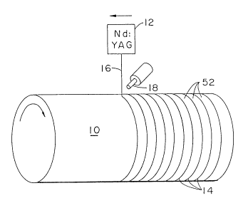
Fig. 1 shows schematically a laser device for precision
teYturing of the surface of a steel roll in accordance with the
principles of the present invention;
Fig. 2 is a photomicrograph of an AISI 52100 steel roll
surface magnified 200 times, the surface being provided with
micron size grooves by the laser of Fig. 1. (Material
displacement on the roll surface caused by depositioll of
vaporized surface material has been removed and the surface
coated with a layer of chrome~.
Fig. 3 is a photomicrograph of a AISI 52100 steel roll
surface (magnified 200 times) that has been teYtured in the
manner of Fig. 2 but which contains material deposition along the
banks of the grooves;
2028711
Fig. 4 is a photomicrograph of a surface of a sheet of
aluminum alloy 5182 magnified 200 times. The sheet underwent a
17% reduction in thickness with a ground roll surfase The
photomicrograph shows a surface texture littered wi-th fissures,
which are small microcracks extending in a direction generally
transverse to the direction of rolling;
Fig. 5 shows the mechanism by which the fissures of Fig.
4 are generated during rolling;
Fig. 6 shows schematically diffuse reflection of light
from a surface having random crests and valleys;
Fig. 7 is a photomicrograph of the surface of a second
sheet of 5182 alloy magnified 200 times, the sheet having been
rolled by a roll whose working surface was prepared by electric
discharge machining;
Fig. 8 is a photomicrograph of another aluminum sheet,
magnified 200 times, showing the substantial absence of
transverse fissures or microcracks;
Fig. 9 shows diagrammatically the surface of a sheet as
rolled by the textured roll of Figure 1; and
Fig. 10 shows a work roll in partial section provided
with minute grooves formed by a micron size cutting insert
mounted in a tool holder.
PREFERP~ED EMBODIMENTS
Referring now to Fig. 1 of the drawings, a tool steel
work roll 10 of a rolling mill (not otherwise depicted in the
drawings) and a Nd:YAG laser 12 are shown schematically in the
2028711
process of machining micron size helical grooves 14 in the roll
surface. The grooves extend continuously in the general
direction of rolling. As depicted (in plan view) grooves 14 are
disposed in a side-by-side manner, though they may, in fact,
comprise a single continuous groove that extends helically about
and along the length of the roll. The number of grooves or
revolutions of a single groove depends upon the width of the
strip to be rolled.
The Nd:YAG laser incorporates a Q switch which provides
a high intensity (pulsed) beam of energy 16 having a wavelength
primarily of 1.064 microns which is in the invisible portion
(near infrared) of the electromagnetic spectrum. Q--switching is
described in some detail in "Solid State Engineerin~", Second
Edition by Walter Koechner, Springer-Verlag, 1988. Basically, it
involves the collection of the energy of the laser's pump ]amp in
the lasing element, and then dumping the collected energy into
short pulses of 100 nanoseconds or so. With Q-switching, the
peak powers of the beam can be increased significantly yet can be
maintained in minute bundles or pulses of energy, sufficient
enough to score metal surfaces.
The width of beam 16 is five to ten micror)s (depending
on the focusing optics within the device) such that, with the
above intensity (pulsed power) of the beam, each pulse of the
beam vaporizes a spot on the surface metal of a tool steel roll
at a width or diameter corresponding to the beam width when the
beam strikes the roll surface without substantial melting of the
steel. A discrete, minute groove 14 is thereby formed in the
2028711
surface of roll 10 when the beam and roll are moved relative to
one other. Preferably, the roll is rotated about its axis and is
moved longitudinally, lengthwise of the roll. The frequency and
wavelength of a Nd:YAG or Excimer laser is such that their beams
can micromachine a groove in a working surface on the order of
the width or cross section of the beams, the wavelength of the
YAG or Eximer laser being more efficient in penetrating (coupling
to) the metal of a workpiece than that of a CO2 laxer If the
frequency of the laser is doubled (which yields a beam at the
1.064 micron wavelength) or tripled (which yields a beam at
one-third the 1.064 micron wavelength), or quadrupled (which
yields a beam at one-fourth the 1.064 micron wavelength) a groove
is formed that is respectively half, one-third or one-fourth the
size of the groove formed without frequency doubling, tripling or
quadrupling. For example, the Nd:YAG laser can form a groove
having a width of eight microns in a steel workpiece Doubling
the laser frequency will form a four micron wide groove due to
the smaller emitted wavelength. The beam produced by frequency
doubling couples more efficiently to steel surfaces than the
original 1.064 micron wavelength of the laser such that the
machining effected by the pulsed beam is finer in cross section.
Frequency doubling can be effected by having the laser end-pump a
Lithium Iodate (LiIO3) crystal. The desired output of the LiIO3
crystal lies in the green portion (0.532 micron) of the
electromagnetic spectrum. A groove width of four to twenty
microns is suitable for rolling aluminum sheet, with a groove
depth in the range of 0.5 to five microns. Depth is controlled
202~711
by the power of the pulsed beam and the time a given section of
steel surface is exposed to the beam.
Generally, the lower the wavelength of the laser beam,
the finer the cut effected by the beam.
In forming groove 14, the vaporized metal is moved ahead
of beam 16 by directing a flow of air from a nozzle 18 located
behind the beam. (As depicted in Fig. 1, nozzle 18 is shown in
perspective and off-center of beam 16 for purposes of
illustration only.) The source of the air can be "plant" air,
which is ordinarily available in factories and shops The flow
of air from 18 is effective to move vaporized metal ahead of the
laser beam to preheat the roll surface just ahead of the beam.
The flow from 18 is also effective to limit the amoullt of
vaporized metal depositing on the banks of the groove (Fig. 3)
and on the optics (not visible in Fig. 1) that focus l)eam 16 on
the roll surface. In the case where metal deposits reach the
banks of the groove, the roll is lightly polished to remove such
deposits after the machining process has been completed. This is
the case of the photomicrograph of the roll surface shown in Fig.
2 of the drawings. In Fig. 2, the grooves are the dark lines
that extend nearly perpendicular to the roll axis. The grooves
are 15.0 microns wide and are spaced from each other by a
distance of 113.0 microns.
The beam of a Nd:YAG laser characteristically produces
generally wedge or truncated triangular shaped grooves (in cross
section transverse of the width of the grooves) in thC surface of
a roll. When rolling a strip 20, such as shown in partial
2D2i~
section in Fig. 9, with such wedge-shaped grooves, ~ slnall
fraction of the strip surface material flows into the grooves
partially filling them. This is a plastic deformati~->n process
known as micro-backwards eY~trusion. The effect of the grooves is
thus to produce narrow wedge-shaped raised portions or ridges 22
(Fig. 9) on the strip surface. Between the ridges are
substantially smooth areas 26 that reflect incident light 28 in a
specular manner 30 such that strip 20 is bright to the human
eye. The ridges 22, being only a few microns wide, are not
clearly visible to the human eye.
An instrument capable of producing continu-~us ~3rooves in
a working surface that are other than wedge shaped is a cutting
tool 35, as shown schematically in Fig. 10 in elevation. The
tool includes an insert 36 having a hard, very minute, micron
size cutting edge 38 of a predetermined shape in cross section.
The cutting edge is capable of cutting a groove 40 iIl roll 10 of
a size and cross sectional shape corresponding to the size and
shape of 36 when it engages the roll surface under appropriate
force, as indicated by arrow 42 in Fig. 10 and the insert and
roll relatively moved. The cross section of the insert can be
substantially triangular (as shown), semi-circular Ol Gaussian
(bell shaped) and hence is not limited to the wedge shape
provided by the beam of laser 12. The insert 36 can be sized to
provide grooves in roll 10 of a depth in the range of 0~25 to
five microns and a width in the range of 2.5 to 25 microns. In
the cases of triangular, semi-circular or Gaussian-shaped
grooves, the width is measured at the base of the grooves, which
2028711
is in the plane of the surface of the roll. The width of the
areas (52) between the grooves lies in the range of five to 300
microns. When such a groove in the roll engages mateLial 20
(Fig. 9) in the rolling, thickness reduction process, the
material of 20 extrudes into the groove to form a ridge
configuration approximating the transverse cross sestion of the
insert.
The material of insert 36 is preferably cubic boron
nitride. Such material is commercially available and used as a
metal cutting (severing) tool. The cutting surface of such a
nitride material is appropriately shaped to a micron size
configuration by a diamond grinding tool or by ion-beam machining.
In Fig. 10, the roll and tool are relatively moved to
form grooves 40. If the grooves (in elevation) are formed as a
single continuous helical groove, the roll can be rotated about
its rolling axis and the tool translated laterally.
Any of the groove shapes provided by insert 36 and laser
beam 16 are such that when a strip of metal is reduced in
thickness in passing between the work rolls of a rolling mill,
which reduction occurs under massive, compressive forces, as
discussed above, the metal of the strip extrudes into the grooves
but is not retained in the grooves such that the roll remains
clean and uncoated with the metal of the strip. This may be
ensured through the use of a roll coating, such as chrome. In
any case, the surface of the s-trip is not marred by debris
clinging to the surface of the roll.
After grooves 14 are formed in the surface of a roll by
14
- 2~2~7 ~1
laser 12, the roll is polished to remove any deposition of roll
material that may not have been cared for by the stream of air
from nozzle 18. Fig. 3 of the micrographs shows a situation
where material deposition 10a of the roll has not only not been
removed but which forms jagged edges on and along the banks of
the grooves in the roll. The jagged edges pick up or seize
material of strip 20 and embed the same (20a) in the surface
grooves. (The embedded material 20a shown in Fig. 3 is a 5182
aluminum alloy, the strip of the material having undergone a
twenty percent reduction in thickness.~ Once embedded, the strip
material is virtually impossible to remove from the grooves. It
is therefore imperative that any material depositio~ on the
groove banks be removed from the roll before it is used. Such
deposits can be removed by a light polishing operation that does
not otherwise affect the roll topography. A suitable polishing
procedure involves manually buffing the roll surface with a cloth
and a fine diamond paste, though other procedures can be used to
remove deposits. The life of the polished roll can be further
extended by plating the roll with a coating of material such as
chrome.
Fig. 4 of the micrographs shows a sheet surface te~ture
44 that is seemingly oriented in one direction yet is actually
quite random and literally littered with small micro cracks or
fissures 46. These fissures generally e~tend transverse to the
direction of rolling. They are the result of thick films of
lubricant 47 locally entrapped and confinecd in ranclom, narrow and
discontinuous depressions 48 in a ground roll surface 10b, as
202~711
depicted in exaggerated form in Fig. 5., i.e., Fig 5 shows a
ground roll surface greatly enlarged to depict random roughness.
Between the depressions are narrow discontinuous peaks that
engage and form elongated, discontinuous depressions 49 in the
surface of sheet 44, as the sheet is reduced in thickness The
lubricant trapped in depressions 48 thereby becomes highly
pressurized, as it cannot escape the depressions, and is forced
against the sheet surface. The pressure is sufficient to open
(crack) the surface of the sheet. This is the problem in Figs. 4
and 5, the sheet in the micrograph of Fig. 4 having undergone a
reduction in thickness of 17%. Such a surface and texture is
also shown diagrammatically and in cross section in Fig 6 of the
drawings. In Fig. 6, the sectional view is employed to show
texture randomness in both a roll and sheet surface
Fig. 7 of the drawings shows the texture of a sheet of
5182 aluminum (magnified 200 times) that has been rolled with a
work roll having its surface machined by electric discharge
machining (EDM). Such a technique produces overlapping pits or
craters in the roll surface. When an aluminum shee-t is rolled
with such a pitted surface, the sheet surface acquires debris
(the dark areas in Fig. 7) in the form of aluminum o~ide which
significantly degrades sheet surface quality. The surface debris
is generated by the random roughness of the roll w~ich produces a
"sand paper" effect, i.e., a fine particle debris occurs that is
similar to that produced when one sands a wood surface ~Jith sand
paper.
Hence, the surfaces of the rolled product of Figs. 4, 5,
16
2028711
6 and 7 are dull, as incident light 28 striking the surfaces is
diffused from the surfaces. The diffused light is indicated by
numeral 50 in Fig. 6. The diffused light in Fig. 6 is in
contrast to the highly directional specularly reflected light 30
in Fig. 9. The diagrammatic presentation of Fig. 9 represents
the surface of sheet 20, as depicted by the micrograph of Fig. 8,
said surface being substantially free of debris and fissures.
Referring again to Figs. 1, 2, and 10, continuous
grooves 14 or 40 in roll 10 are separated by substantially
smooth, relatively broad areas 52 that extend about the roll
surface, with the grooves, the width of the broad areas being on
the order of five to 300 microns. The width of these areas, in
any given case, is chosen in accordance with such rolling
parameters as the material (alloy) being reduced in thickness,
the composition of the lubricant employed and speed of the
rolling process. Areas 52 provide broad smooth bearing surfaces
that bear against strip 20 (Fig. 8) during the rolling process to
form the broad, smooth and bright planar surfaces 26 on the
surface of the strip. Areas 52 reduce the thickness of strip 20
under boundary lubrication conditions, i.e., any lubricant
existing or entering between roll surfaces 52 and strip surfaces
26 is forced from the broad areas of 52 into grooves 14 or 40
provided in the roll such that virtually no thick film of
lubricant is maintained between surfaces 52 and 26 during the
rolling process. When the lubricant reaches the grooves it is
freely channelled therealong as the rolls rotate against the
strip. The lubricant is thus not confined in the manner
2~28 71I
described above in connection with the discontinuous depressions
of ground rolls. Since the lubricant is not confined, the
pressure of the lubricant does not grow and increase io cause
cracking of the strip surface. In the broad areas of ~2 and 2~,
no lubricant is available to open up the strip surface so that
the strip exiting the mill is substantially free of transverse
fissures. Neither do surfaces 26 contain random size valleys and
crests, as the surface of roll 10 does not contain random valleys
and crests. The surface of strip 20 is now comprised of a
combination of broad, substantially smooth areas 26 of precisely
chosen widths separated by ridges 22 of precise height, wid.th,
and configuration.
Further, in the process of reducing the th.icktless of
strip 20, the bearing areas 52 of roll 10 "smear" the ~surface of
the strip engaging such bearing areas. Smearing is a process in
which the force of the rolls bearing against the strip being
rolled smooths out any remaining uneven profiles on the strip
surface so that its specularly reflective capability is further
enhanced.
A further enhancement of reflectivity is effected by
highly polishing the surface vf roll 10 before it i., machined by
laser 12 or tool 35. This provides highly polished bearing areas
52 which transfer their polished characteristic to tlle rolled
product in the thicknes.s reduction process, and enha.n.e the
smearing or smoothing process.
Roll 10 of the invention is thus provided. wi-th an
engineered, predictable, non-random surface finish alld texture
18
202~711
made possible by pul.sed laser beam 16 or cutting insert 36. Such
an engineered roll surface provides an anisotropic, predictable,
engineered strip having the desired uniformly bright surface.
The texture of the roll is anisotropic, as it is provided with
discrete grooves 14 or 40 spaced apart by bearing areas 52, with
a pitch to groove ratio of 2.0 or greater.
While the invention has been described in terms of
preferred embodiments, the claims appended hereto a.re intended to
encompass all embodiments which fall within the spirit of the
invention.
What is claimed is:
19