Note: Descriptions are shown in the official language in which they were submitted.
~ ~2~
SPI:~'C~I~IC~TION
'o~-~VOVE~ ~t~BRIC AND MET~IOD AND APPARATUS FOR
MA~ING T~IE SAME
~Technical ~ie-ld]
The present invention relates to a non-woven fabric
obtained bY spinning a polymeric material and a method and
apparatus ~or making the same and, more particularly, to a
non-~voven fabric in which filaments composing the non-woven
fabric are collected to form an ellipse having an elongated
major axi;s and the filaments are arranged in substantially
the major axis direction and a method and apparatus -for
making the same.
[Background Art]
Random-laid non-woven fabrics made by a conventional
spun bonding method and the like are excellent in bulkiness
and texture. The random-laid non-woven fabrics also have
excellent w~ater permeability and filtering characteristics.
Since, however, filaments are arran~ed substantially at
random in the random-laid non-woven fabrics, the random-laid
non-~voven ~abrics have only a poor dimensional stability and
a small strength in the longitudinal and transverse
directions. In order to improve the stren~th. the
~5 conventional random-laid non-woven fabrics may be stretche~.
When the conventional randolll-laid non-woverl fabrics are
simply stretched in the longitudinal or transverse
' .~
'
.
. ~
- 2 - ~2~3
cl:irection, ilowev~r, an interengagement or bondage connecting
~he Lilamen~s is o-fterl disconnected, and the filaments
themse:Lves are not stretched. Therefore, the strength o~f
the non-~voven ~abrics :is not increasecl.
Ln addition, a technique of biaxially stretching
normal non-woven fabrics is available as disclosed in
British Pa-tent No. 1,213,441. When normal non-woven fabrics
are bia,Yially stretched, however, a;n ef-ficiency of
stretching filaments composing the non-woven fabrics is low.
Therefore, the s-trength of the non-woven fabrics cannot be
sufficiently increased.
The present inventors, therefore, proposed a method
and apparatus for stretching a non-woven fabric in the
longitudinal or transverse direction, a means of cross-
laminating a longitudinally stretched non-woven -fabric and a
transversely stretched non-woven ~abric, a means of
unidirectionally arranging spun -filaments, and the like in
Japanese Patent Application No. Sho 62-173927. The
inverltion of this prior application is characteri~ed in that
a long-fiber random-laid non-woven fabric obtained by
spinning un-oriented filaments is stretched in a
predetermined direction so that the filaments composing the
non-woven -fabr'ic are substantially stretched to cause a
mo:lecu:Lar orierltation. As disclosed in this prior
application, when a non-woven -fabric in which -filalllents are
unidirectionally arranged is stretched in an arranging
direction o-f the filaments, the filaments are stretched, ancl
2~2~8~3
the strength o-L' the non~ oven ~'abr:ic is increased. :In
accordarlce ~v:ith t:he type o-f -r:i]aments com~)osirlg a non-~Yoven
~ab~ic, if on:ly tl~e fi.lamenls are arrangecl, a sat:isfactory
strength or d.ilnerls.ioncll stabi:L.i.ty can be obtained i.n an
~rrang:ing direction of the f:ilaments ~vithout stretching the
fabric.
A method of making a sheet by shaking fibers is
disclosed in Japanese Patent Publication No. Sho 45-10779.
In this method, a fluid is alternately, intermittently
sprayed -from right and lert directions to a portion close to
~ a spray outlet of fibers, thereby shaking the fibers to make
a sheet~
[Disclosure of Invention]
It is an object of the present invention to provide a
non-~voven fabric having a good dimensional stability and a
large strength in both the longitudinal and transverse
directions and a method and apparatus for making the same~
t~ non~ oven fabric according to the present invention
includes a ~ilament-laid layer in ~vhich one or more
~0 continuous filaments obtained by spinning a polymeric
material are collected to form an ellipse having an
elongated major a~is and the filaments are arranged in a
substantially ma~jor axis direction~ That is, one or more
cont:inllous filaments are spirally collected a:long a shape in
~5 ~vhich an ellipse having an elongated major axis is gradually
sh.iftecl :in a p:Lane. Since one or more continuous filalllents
are substantiallY unidirectionally arranged, the strength in
.
CA 020288~3 1998-07-02
the arranging direction is larger than those of
conventional random-laid non-woven fabrics.
The above filament-laid layer is preferably
stretched in an arranging direction of the filaments.
The strength of the non-woven fabric is further
increased by stretching.
The present invention also provides a method
and apparatus for making the non-woven characterized in
that filaments consisting of a polymeric material spun
from a spinning nozzle are vibrated, the vibration of
the filaments are amplified to collect the filaments
into an ellipse having an elongated major axis, and the
filaments are scattered and spread so as to be arranged
in a substantially major axis direction. In
particular, a method of making the non-woven fabric
according to the present invention comprises the steps
of spinning filaments consisting of a polymeric
material, vibrating the filaments, amplifying the
vibration of the filaments, and collecting the
filaments to form an ellipse having an elongated major
axis so that the filaments are arranged in a
substantially major axis direction. An apparatus of
making the non-woven fabric according to the present
invention comprises means for spinning filaments
consisting of a polymeric material, means for vibrating
the filaments, means for amplifying the vibration of
the filament, stage means for arranging the filaments
on a plane to form a sheet, and means for moving the
filament spinning means and the stage means relative to
each other.
According to one aspect of the present
invention, thre is provided a method of making a non-
woven fabric, comprising the steps of (a) spinning afilament composed of polymeric material; (b) vibrating
the filament; (c) amplifying the vibration of the
filament in a predetermined first axis direction
CA 020288~3 1998-07-02
- 4a -
whereby the filament is scattered, the scattered
filament depicting an ellipse having a elongated major
axis as a locus in its cross section every one cycle of
the vibration, the direction of the major axis
corresponding to the first axis, the filament vibration
amplifying step being started at a point other than the
starting point of the filament vibration step; and (d)
collecting the scattered filaments into a series of
ellipses so that the major axis of each ellipse
deviates from the immediately adjacent ellipse in a
predetermined second axis direction crossing the first
axis and the major axes of the ellipses are arranged
substantially in parallel.
According to another aspect of the inention,
there is provided a method of making a non-woven
fabric, comprising the steps of (a) spinning a filament
composed of a polymeric material; (b) vibrating the
filament; ~c) amplifying the vibration of the filament;
and (d) collecting the filament into an elliptic shape
having an elongated major axis and arranging the
filament in the direction of substantially the major
axis. The filament vibration amplifying step (c)
comprises continuously striking a pair of fluid flows
jetting in directions opposite to one another on the
substantial center of vibration of the vibrating
filament to direct the fluid flows in a direction
perpendicular to the jetting direction of the fluid
flows, such that the amplitude of the vibrating
filament is amplified in the perpendicular direction
and wherein in said filament vibration amplifying step,
the amplification of vibration of the vibrating
filament starts at a point other than the starting
point of the filament vibration in the step of
vibrating the filament, the filament vibration
CA 020288~3 1998-07-02
- 4b -
amplifying step comprising discontinously amplifying
the amplitude of the vibrating element.
According to a further aspect of the
invention, there is provided a method of making a non-
woven fabric, comprising the steps of (a) spinning a
filament composed of polymeric material; (b) vibrating
the filament; (c) amplifying the vibration of the
filament; and (d) collecting the filament into an
elliptic shape having an elongated major axis and
arranging the filament in the direction of
substantially the major axis. The filament vibration
amplifying step (c) comprises continuously crossing a
pair of fluid flows jetting in directions opposite to
each other within a vibration range of the filament
without striking the fluid flows whereby the vibrating
filament is blown away in the direction of one of the
fluid flows when the filament crosses one of the fluid
flows and the vibrating filament is blown away in the
direction of the other fluid flow when the filament
crosses the other fluid flow, whereby the direction of
vibration of the filament is directed in a direction
parallel to the jetting direction of the fluid flows
and the vibration is amplified and wherein in the
filament vibration amplifying step, the amplification
of vibration of the vibrating filament starts at a
point other than the filament vibration starting point
of the step of vibrating the filament, the filament
vibration amplifying step comprising discontinously
amplifying the amplitude of the vibrating filament.
According to yet another aspect of the
invention, there is provided a method of making a non-
woven fabric, comprising the steps of (a) spinning afilament composed of a polymeric material; (b)
vibrating the filament; (c) amplifying the vibration of
the filament, the amplifying step being started at a
CA 020288~3 1998-07-02
- 4C -
point other than the starting point of the filament
vibration step; and (d) collecting the filament into an
elliptic shape having an elongated major axis and
arranging the filament in the direction of
substantially the major axis. The filament vibration
amplifying step (c) comprises continuously striking a
pair of fluid flows on the substantial center of
vibration of the vibrating filament to direct the fluid
flows in a direction perpendicular to a jetting
direction of the fluid flows, whereby the amplitude of
the vibrating filament is amplified in the
perpendicular direction.
-,- 2~88~
Examp:les o[! the polYmeric material are a polymer:ic
ma~ericll (lisso:lved or clispersed :in the form of an emulsior
in a so:lvent and a me:lted polymeric material.
~ laments are pre~ferablY v:ibrated spirally or in
~i(rz~g
'I'he vibration of filaments is pref'erably performed as
described in the following items (1), (2), and (3).
(1) A small amount of fluid is applied at a small
pressure froln a portion close to a spinning nozzle
imme(liately after filaments are spun, thereby vibrating the
~ilaments.
(2) An-electric charge :is applied to filaments to
applv an electric or magnetic -field having an alternately
changing polarity, thereby vibrating the -filaments.
(3) A spinning nozzle is vibrated by a circular
motion or reciprocation, thereby vibrating ~ilaments.
~ ilaments are pref'erably spread ~vhile vibrating
filaments have dra-ft properties of t~Yice or more. Normally,
draft properties (draft ratioj in spinning is represented
~0 by: -
(take-up rate~/(injection rate at spinning nozzle)
In this case, filaments injected -f'rom a spinn:ing nozzle are
e:longated :in vibrating and spreading steps, and this
stretching ratio is defined as the draft properties.
~5 Spread:ing o-f -~ilaments is pre~erably performed such
~hat a pair or more of f:Luid flows ~vhich are substantially
symllletrica:L about ~'ilaments are continuously supplied
2 ~
s i de~cl~ s on tt)e r ilaments t;hereby scattering and spread:ing
~l1e ~'iLal11ents to be ul1i.(1:irectiona:Lly arranged. :I:n
l~articu:lar the f':Lu:i~l rl.ows are preferab1.v continuous:Ly
struck on the ~ Laments to scatter the ~ilaments in a
lirection perpendicular to a spray direction of the fl-1:id
~lows. ~lternativelY. the fluid flows are continuously
crossed (staggered) within a vibration range o-f the
filaments to scatter the filaments in a direction parallel
to the spray direction of the fluid -flows~
~t' the ~'ilaments are stretched in an arranging
direction after they are unid:irectionally arranged the
strength of a non-woven fabric is further enhanced.
~ Vhen a non-woven fabric according to the present
invention is laminated on another base material or another
non-woven fabric. a non-wo--en fabric having-a lar~e strength
can be obtained. Especial]y w11en a non~ oven fabric in
which ri:laments are arranged in a first direction and a non-
woven fabric in which filaments are arran~ed in a second
direction subs~antially perpendicular to the -first direction
~() are laminated. the strength of a non-woven fabric is further
.increased~
.\ccord:ing to the method and apparatus of the present
.in~er1tiol1 a one-~Yay-or:ier1t.e(l non-woven fabric wh:ich
con~ent:ionally has a ver~ narro-Y stability range can be
~5 stclbly made to have a ~ood one-way orientation regardless of
the t~pe of l)o:lyo1er. In add:ition the method and apparatus
_ 7 _ 2~28~3
of the present invention can be applied to any o-f a wet-
spinning process, a dry-sp:inning process, arld an emuls:ion-
spinning process. Accolding to the present invention, any
spun ~ilaments can be stably turned or vibrated and
scattered to be unidirectionally arranged with a good
orientation. Therefore. filaments arranged in the
longitudinal or transverse direction can be easily made in
any of the wet-, dry-, and emulsion-spinning processes. The
obtained fibers can be united with a cross-arranged non-
woven fabric to make a non-woven fabric having a high
dimensional stabilitY in both the longitudinal and
transverse directions. In addition, even a ~olten polymer
having a high viscosity can be formed into filaments
unidirectionally arranged well. This polymer is most
suitably used in making o-f a non-woven fabric which is
stretched in an arranging direction of filaments to gain a
large strength.
[Brief Description of Drawings]
Figs. lA to lC are schematic perspective views
~0 showing outer appearances of non-woven fabrics according to
the present inven-tion, in which filaments are arranged in a
transverse direction (w.idthwise direction of a non-woven
~'abric);
l~igs. 2A to 2C are schematic perspective views
~5 showing outer appearances of non-woven fabrics according to
the present invent:ion, in which filaments are arranged in a
'
2~28~3
-- 8
longitudinal directiorl (lengthwise direction of a non-woven
fablic);
I'igs ~ to 3C are schematic perspective views
showirl~ ou~er appearances Or non-woven fabrics according to
the present invention. in which filaments are obliquely
arranged;
Fig 4 is a schematic perspective view showing an
example of making a non-woven -~abric according to the
present invention;
Fig 5 is a schematic perspective view showing
another example of making a non-woven fabric according to
the present invention;
Fig 6 is a sectional view showing a pair o-f grooved
rolls o~ a non-woven fabric transverse-stretching apparatus;
Fig. 7 is a flow diagram sho-ving individual steps
according to an embodiment o-f a method o-f making a non-woven
fabric according to the present invention;
Fig. 8 is a bottom view showing a practical
arrangement of a spinning nozzle for forming filaments to be
~0 arranged in the transverse direction of a non-woven fabric;
Fig. 9 is a schematic side sectional view showing an
apparatus, having the spinning nozzle shown in Fig 8, -for
making a non-woven fabric having filaments arranged in the
transverse direction;
~5 Fig 10 is a sectional view taken along a line V - V
i~l lig 9;
_ 9 _ 2~288~3
l~igs. llA to llD are side sectional views showing
practica:L arrangements of a sp:inning nozzle for vibrating
filaments;
Figs. 12A to 12D are bottom vie-vs of spinning noz~:Les
showing arrangements of injection holes of small amounts of
fluid for vibrating spun filaments;
Figs. 13A and 13B are schematic views showing the
manner of forcing high-pressure fluid -flows on vibrating
filaments to scatter and spread the filaments;
Figs. 14A to 14C are schematic perspective views
showing practical arrangements o-f filaments of a non-woven
fabric obtained by cro~s-laminating unidirectional non-woven
fabrics;
Figs. 15A and 15B are plane and side views showing a
practical arrangement of a mechanism for vibrating a nozzle;
Figs. 16A and 16B are plane and side views showing a
practical arrangement of a mechanism for electromagnetically
vibrating a nozzle; and
Fig. 17 is a schematic perspective view showing the
Inanner o-f laminating non--voven fabric having a strength in
the longitudinal direction and a non-woven fabric having a
strength in the transverse direction.
[Best ~lode of Carrying Out the :[nvention]
'rhe present invention will be described in detail
~5 be:Low with re~erence to the accompanying drawings.
20288~i3
-- .~ o
Fig. lA :is a schematic perspective view showing an
outer appearance Or a non-woven fabric (unidirectional non-
voven ~abr:ic) 10 accord-ing to the present invention in ~vh:ici~
filaments are arranged in the transverse direction.
Rel'err:ing to Fig. lA, a direction indicated by an arro~v 11
indicates the longitudinal direction, and a d:irection
indicated by an arrow 12 indicates -the transverse direction.
A direction indicated by hatching indicates the arranging
direction of the filaments. Note that in Figs. lB and lC,
~ to 2C, and 3A to 3C, the arrows 11 and 12 and hatching
have the same meanings as in Fig. lA.
Fig. lB shows a filament 13 by reducing the density
of an arrangement in order to explain the filament
arrangement sho~vn in Fig. lA. As shown in Figs. lB. the
filament is collected to form an ellipse having a very long
major axis. As a result. the filament is arranged in a
major axis direction (transverse direction). Actually, the
filament 13 is arranged more densely. The ~ilament 13 may
be a plurality of filaments (as shown in, e.g., Figs. llB,
llC, and llD) ~vhich are spun from a plurality of spinning
nozzles of a single no~zle and vibrated and spread by a
single nozzle vibrating/spreading apparatus. ~or
:illustrative simplicity, however, only one tilament :is showr
in ~ig. lB. In addit:ion, although the f'ilament is regularly
arranged in Fig. lB, it is sometimes scattered more
irregularlY~ 'l'his is the same in Figs. 2B and 3B.
- lL _. 2~28~i3
'rhe unidirectional non-woven fabric 10 shown in ~lgs.
lA and lB has a :f:ilaillent-lai('i layer in ~vhich one continuous
filament (or a plurallty o-f f:ilaments) 13 obtained by
spinn:ing a polYmer:ic mater:ia:l is arranged in substan~ially
the transverse direction.
Fig. lC shows a unidiirectional non-woven fabric 17 in
which three arrays 14 to 16 in each of which a filament is
arranged in the transverse direction are arranged in
parallel ~Yi th each other.
~ig. 2A is a schematic perspective view showing a
unidirectional non-woven fabric 20 according to the present
invention in which a ~ilament is arranged in the
longitudinal direction.
Fig. 2B shows a filament 23 by reducing the density
o~ an arrangement in order to explain the filament
arrangement shown in ~i~. 2A. Actually, the filament 23 is
arranged more densely. The unidirectional non-woven fabric
shown in Figs. 2A and 2B has a filament-laid layer in which
one continuous filament (or a plurality o-f filaments) 23
~0 obtained by spinning a polYmeric material is arranged in
substantially the longitudinal direction.
Fig. 2C shows a unidirectional non-woven fabric 29 in
which five arrays 24 to 28 in each of whicll a f:ilament is
arranged in the longi-tudina:L direction are arranged in
parallel with each other.
- l2 - 2~8~i3
~ ig. 3A is a scllel1latic perspective v:iew show:in~ a
uTlidirect-iona:L non-woverl ~ab~:ic 30 accordlng to the present
invent:ion in whictl a ~:ilament is ob:Liquely arranged.
~ ig. 3B shows a ~ lament 33 by reducing the density
of an arrangemerlt in order to expla:in the filament
arrangement shown in Fig. 3A. Actually, the filament 33 is
arranged more densely. 'I'he unidirectional non-woven fabric
30 shown in Figs. 3A and 3B has filament-laid layer in which
one continuous filament (or a plurality of filaments) 33
obtained by spinning a polYmeric material is subs-tantially
obliquely arranged.
Fig. 3C shows a unid:irectional non-woven fabric 37 in
which three arrays 34 to 3~ in each of which a -filament is
obliquely arranged are arranged in parallel with each other.
In each of the unidirectional non-woven fabrics shown
in Figs. lA to 3C, one or more continuous filaments are
substantially unidirectionallY arranged. Therefore, the
strength in the arranging direction is larger than those of
conventional non-woven fabrics.
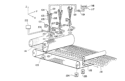
~0 Fig. 4 shows an example of making a non-woven fabric
according to the present invention.
Spinning of -filaments will be described first. A
~iber-forming polymer 118 is dissolved in a solvent in a
d:issolving pot 117. This polymer 118 is supplied to each
25 nozzle 102 through a condu:it 101 at a predetermined pressure
by a gear pump 119. 'l'he nozzle 102 has a large number of
spinning nozzles. The polymer 118 is extruded as a
_ I~3 - ~ 3
multifilamerlt from the nozz:le 102. ~~n e~truded f:i:Lalllerlt 103
is spun into a coagu:La~irlg solution 106 supp:Lied L'rolll a
correspond:irlg in:let port 10~ into a correspond:ing ~unne:L-
shaped coagu:Lating bath ]0~
A mechanism ~'or vibrating a filament will be
described below. A root 107 as a lower linear portion of
each funnel 107 is fle,Yible. This linear port:ion 107 is
vibrated by a vibrator 121 (V) in the transverse direction.
In Fig. 4, the X, Y, and Z a,YeS are se-t such that the line
(longitudinal) direction corresponds to the X axis, the
transverse clirection corresponds to the Y axis, and the
vertical direction corresponds to the Z axis. Upon
vibration of the Linear portion 107, the spun multifilament
lOS is vibrated in zigzag in the Y direction.
A mechanism for amplifying vibration of a -filament
will be described. Iligh-pressure fluid flows 110 and 110'
are applied on the multifilament 108 vibrated in zigzag.
The high-pressure fluid flows 110 and 110' are supplied from
a fluid supplY device 122. Although similar fluid flows are
~0 supplied to other conduits, they are not shown f'or
illustrative simplicity. The high-pressure fluid flows 110
and llO' are sprayed -~rom conduits 109 and 109' in opposite
d:irectlons a:long the ~ a,~:is. '~'he high-pressure fluid flows
]10 and 110 ~Ire sprayed toward the center o-f the width o~' a
~5 z:i~za~ f'ormed by the z:i~zagging filament 108. The high-
~)ressure f.luid -fLows 110 and 110' strike against each other
at the center of the width of the zigzag of the f:ilament
2~2~8~3
10~. The -flu:id flows llO and 110 may be a coagulating
so:Lut:ion 106 or another type o~ coagulating solution.
.~lternatlve:Ly. tile -fluicl L':Lo~vs llO and 110 may be higtl-
pressure air streams.
By an impact of the struck fluid flows 110 and 110
the zigzag width is increased in -the Y direction to form the
filament into a filament group 111 and the filament group
111 is collected on a net 112.
~ig. 4 shows two more sets of devices for vibrating a
spun filament in zigzag in the transverse direction.
Although a larger number of sets are installed in both the
transverse d:irection (Y direction) and the longitudinal
direction (machine direction i.e. the ~ direction) in an
actual apparatus they are omitted from Fig. 4 for
illustrative simplicity.
A step o~ arranging a filament ~vill be described
below .
The net 112 is :~ormed cylindrically and rotated by a
driving means 123 (M). Most of the coagulating solution 106
~0 and the -fluid flows 110 and 110 are separated -from the
filament through the cylindrical net 112. ~ vaccum suction
means may be disposed .inside the cylindrical net 112 to
improve separation of the coagulating solution.
An endless conveyor belt 113 is disposed in almost
~5 contact w:ith the lower portion of the cylindrical net 1].2.
The conveyor belt 113 is driven to be circulated by a
driving means 124. A stage means for arranging a filament
. . ~ . , .
- 15 - 2~28~3
into a sheet is constituted by the cyllndrical net 1].2, the
con~eyor be:Lt ll;3, and the L:ike. ~Vhen the cylindr:lcal net
11'~ and the conveyor be:Lt 113 are dr:iven the driving means
1?~ an(l .1.24, the stage meclns :is moved relat:ive to the
mechanism for sp:inn:ing a -~:i.lament.
Ref'erence numeral 11~ denotes a web in which fibers
are mainly arranged in the longitudinal direction and which
has a strength in the longitudinal direction. The web 114
is guided into and conveyed by the conveyor belt 113. The
10~veb 114 is laminated with the collected filament group 111
under the cyl:indrical net 112. The laminated web is
convey~d to a nip roll 115 and -formed into a laminated non-
woven fabric 116. Re-ference numeral 125 denotes a driving
means for driving the nip roll 115.
15Referring to Fig. 4, the web arranged in the
transverse direction is roughly illustrated so that the
arranging direct:ion o-~ the filaments is clearly shown.
t~ctually, however. the filaments are arranged more densely.
The laminated non-woven fabric 116 has a filament
layer which is spirally collected so that the filaments are
arranged substantially along a shape in which an ellipse
having an elongated major a,YiS is gradually shi-fted in a
plarle .
~lthou~h the lam:inated non-woven fabric 16 can be
~5 directly used as a product. coagulation or scouring may be
perforllled as needed. In addition, an adhesion or bonding
treatment may b~ performed in order to strengthen adhesion
2~28~3
between thc f'ibers or webs before the non-woven fabri( :is
used as a produc~.
F:ig. 5 shows another example o-f making non-woven
L'abric according t(> the present lnvention. Referrill~ to
~ig. S, a po:Lymer 217 is melted and kneaded by an extruder
218. The polymer 217 is ~uided to a spinning nozzle through
a flexible conduit 219. The conduit; 219 is circular:Ly
vibrated by a vibrating means 241 (V). Therefore, a
spinning no~le 220 is also circularly moved. By this
circular motion o-f the spinn:ing nozzle 220, a filament 221
spun from the spinning no~zle moves downward ~vhile it is
spirally turned (vibratedi).
A pair of high-pressure air streams 223 and 223' are
sprayed -from pipes 222 and 222' in the Y direction of the x,
Y, and Z axes shown in Fig. 5. The air is supplied from a
supply means 242. The pair of high-pressure air streams 223
and 223' are spraye~ to cross (pass) each other at shi-fted
intersections close to the central axis of the spiral orbit
(as ~Yill be described in detail later with reference to Fig.
~~ 13B). The -filamerlt splrally moved downward is widened in
the transverse direction (Y direction) by the crossed air
streams. 'l'herefore, the filament is collected on a conveyor
belt 225 as a ~filalllerlt web 224 whlc}l is arranged in
s~lbstantially tlle transverse direction.
~5 'I'he conveyor belt 225 :is driven by a driving means
243 (M~. 'I'he conveyor be:lt 225 conveys the transversely
arranged ~veb to a stretchi.rlg means. A conduit 226 for
. . . .
- 2~28~
spraying an adhes:ive 227 is d:isposed at a posit:ion shi~ted
~rom the conve~or belt 22~. 'rhe adhesive 227 :is sprayed to
the transversely arranged ~veb at this position. As a
result, a bond:ing strength at bonde(l portions bet~Yeen ~:ibers
in the web is enhanced, and a ~veb 228 is conveyed to a
stretching step.
Two pulleys 229 and 229' are disposed to be widened
toward the end in the stretching means. The pulleys 229 and
229' are driven the driv:ing means 244 ~I). Two ends o-f the
web 228 are held by the pulleys 229 and 229r and belts 230
and 230'. The web 228 is stretched in the transverse
direction by the two pulleys 229 and 229' disposed to be
widened toward the end. A heating medium (normally a hot
wind) is -~illed in a stretching chamber 231. When the web
223 must be uniformly heated, the heating medium is sprayed
through the web. ~-
In this manner, a transversely stretched web 232 is
made.
Although the transversely stretched web can be
~0 directly used as a product, it may be laminated and bonded
to a longitudinallY oriented ~veb in another step to make a
cross-laminated non-woven fabric having a strength :in both
the long:itudinal and transverse directions.
~ig, 6 shows another e~ample o~ a stretching means
~5 -Lor- stretching a ~veb in the transverse direction. Re-~erring
to ~:ig. 6, a web 234 is stretched in the transverse
direct:iorl between grooved rolls 233 and 233'. When such
- 18 - ~288~3
grooved rolls are to be used, a plurality of palrs o-
~g1oove(1 rolls are preferably disposecl.
Although a method of' stretching a web in the
trilnsve1se direG~:ion is sho~vn in each of Figs. 4 and 5, the
spraying direction of the high-pressure air strearns 223 and
2~3' may be changed through 90~ to make a longitudinall~
arranged web. The strength of a longitudinally arranged web
can be further increased by stretching the web between rolls
or b~ a rolling means.
Fig. 7 is a f'low diagram showing individual processes
according to an embodiment o-f' a method of making a non-woven
fabric of the present invention. In Fig. 7, rectangle
blocks denote materials, and elliptical blocks denote means
or processing.
- 15 Referring to Fig. 7, step I is a spinning process.
In the spinning process, a dissolved or melted polymer is
supplied under pressure to a spinning nozzle by an e.Ytruder
or a gear pump and spun into a filament by the spinning
nozzle. In this process, any of a melt spinning process, a
dry spinning process using a molten spun yarn and a solvent,
a wet spinning process using a coagulating bath, and an
emulsion spinning process as a special spinning me-thod can
t)e used.
Step II is a v:ibrating process of v:ibrating the spun
~5 ~':ilament in zigzag or spirally. In this process, the
l'ilament is vibrated by various types of methods to be
described later with reference to Fig. ll. An amplitude of
. .
,
'
- L9 - 2~288~3
the vibration :is several millimeters to several tens
mi:L:limeters.
Step :[:LI is a spreadlng process o-f amplifying the
~ibratiorl of ~he vibrated l'i:Lament to spread the filamerlt
into a width o-f several hundred millimeters. As shown in
Fig. llA or llB, spreading of a -filament can be performed by
a method of striking or crossing high-pressure -fluid flows.
Step IV is a sheet formation process. In the sheet
formation process, a -filament spread in a predetermined
direction by the spreading process is continuously collected
to form a sheet. As a result, the filament is made into a
unidirectional non-woven fabric ~. This unidirectional non-
~voven fabric a can be singly used as a product.
Step V is a s-tretching process. In the stretching
process, the unidirec-tional non-~voven fabric ~ is unia~ially
stretched in the arranging direction. If a strength is
insu-~'ficient by only spinni.ng, a stronger product can be
obtained via this stretching process.
Step VI is a laminating/bonding process. In the
~~ laminating/bonding process, the unidirectional non-woven
fabric ~ and a unidirectional non-~voven -fabric ~ having
d:ifferent arrangirlg directions are cross-laminated/bonded.
~\s a result, var:ious types of cross-laminated non-~voven
rabric as shown in ~ig. 1~ to be described later. I~ the
~5 strengtll of a non-woven fabr:ic is insufficient by onlY
spinn:ing, a cross-laminated non-~voven -fabric having a
sufficierlt strength can be obtained by only
2~2~8~
lam:inating/bond:ing. If a strength :is insu-fficient by on:Ly
spinninr the ~1n:iclirect:iorlal non-woven fabr:ic ~ and/or
unidirect:iorla:l non--Yoven ~'abric ~ are stretched in step ~/
an(l then laminated~bonded. As a result~ a stronger prodllct
can be obtained.
Step V is a biaxial stretching process. The biaxial
stretching process is another method of performing
s-tretching to obtain a strong non-woven -~abric. In the
biaxial stretching process the unidirectional non-~voven
fabrics ~ and ~ are laminated/bonded and then biaYially
stretched.
Formation of an un-oriented filament performed by an
apparatus for vibrating a filament by a small amount of air
will be described with reference to Figs. 8 to 10.
A spinning aPParatus comprises a nozzle plate or a
spinneret having at its central portion a spinning nozzle
308 for e~truding a polymeric material to be spun downward
to form a filament 309 and a pluralitY of (six in Figs. 8
to 10) oblique first air holes 310-1 to 310-6. The air
holes 310-1 to 310-6 are disposed circum-ferentially around
the spinning nozzle 308 at equal angular intervals to spray
air against the filament 3()9 thereby sp:irally moving and
extrucling the -f:ilament 309 :into a do~vn~varcl spread conica:l
shape.
~5 Tt~e spinning appara-tlls has a pair o-f cl:iametrically
opposite second air holes 311 -for horizontally spraying air.
The air holes 311 are disposed at oppos:ite sides of the
2~288~
spinning nozzle 308 and below the -first air holes 310-1 to
310-6 The second air holes 311 spray air streams in
opposite directions para:lle:L to the direction of movement o-f'
a scteen mesh 312. t~S a resu:Lt, the air streams strike
direct:Ly belo-v the spinning nozzle 308. The two air streams
thus struck spirally moves the filatnent 309, and the
filament 309 is spread outward in a direction (transverse
direction) perpendicular to the direction of movement o~ a
~Yeb of a non-woven -~abric 313. In this manner, the filament
]0 30g is arranged on the screen mesh 312.
The oblique -first air holes 310-1 to 310-6 of the
; spinneret extend tangentially to the spinning no~le 308 as
shown in Fig. 8 and also extend obliquely at an angle,with
respect to the central axis of the spinning nozzle 308 as
sho~Yn in Fig. 9. With this arrangement, air blown-off from
the respective air holes 310-l to 310-6 substantially
converge at a region spaced downwardly from the spinning
no~le 308 by a distance of several centimeters to ten
centimeters or more. The streams of air thus converged
cause the spiral movement of the -filament 9 as described
above. The filament 309 deposited on the screen mesh 312 is
mainly arranged :in the widthwise direction of the non-wover
abric 313. In this manner, the strength of the non-wover
t'abric 313 is enhanced especial:Ly in its widthwise
direction.
Alternatively. the t'irst air holes 310-1 to 310-6 may
be arranged linearly in the vicinity of the spinning no~le
- ~2 - 2028~3
308 on condition that a:ir blo~vn-of:f from the air holes 310-1
to 310-6 strikes the filameflt 309 to thereby cause the same
~o be sprea(l to some e.~tent hefore the filament 309 is
widely spread by the air blo~n-o-~ -f'rom the second air holes
311. rhe non-woven fabr:ic 313 produced by the spinning
apparatus with a single spinneret has a ~Yidth of about 100
to 300 mm. A non-woven fabric having a width more than 300
mm can be produced by a spinning apparatus having a
plurality of transversely arranged spinnerets. ~urthermore.
it is possible to produce a dense non-woven -fabric at a high
speed by utilizing a spinning apparatus in which a plurality
of spinnere~s are arranged in the lengthwise direction of
the non-woven -fabric.
If this spinning is melt spinning, the air blown-off
15 from the first air holes 310-1 to 310-6 and the air blown-
off from the second air holes 311 are heated at a
temperature higher than the melting temperature of a
polymeric material used for the -formation o-f the filament
309. Heating of either one of the air supplied from the
~0 first air holes 310-l to 310-6 and the air supplied from the
second air holes 311 may be omitted depending on the kind of
the polymeric material used. ~Vith the use of the hot air,
che fi:lament 309 whi:Le being formed does not undergo
substantia:L molecular orientation.
~5 'I'he spinneret described above can be used -for the
f'orma~ion of a non-woven fabric composed of un-oriented
fi:laments arranged substantially in the lengthwise direction
- ~3 - 2~2~3
of the -~abric. :In this instance, the spinneret ls turned
about the centrcll a,~is of the spinning nozzle 308 through an
ang1e o~ 90~ f'roln the positiorl sho~Yn :in ~ig, ~ to a pOSitiGn
in ~vhich the second air holes ~ll extend perpendicu:Larly to
the dircction of movement of the non-~Yoven fabric ~vhi:Le
being produced. The thus formed non-~voven fabric hàs a
strength in especially its length~vise direction.
A method or means for vibrat:ing a spun filament will
be described in detail belo~Y.
A spun filament must be spiralIy turned or
reciprocated (to be referred to as vibrated hereinafter for
simplicity) in zigzag with an iamplitude o-~ several to
several tens millimeters, and preferably, five to 50
millimeters at a period of several tens to several hundreds
times~min., and preferablY~ 300 times/min. or more. In
order to vibrate a filament, (l) a fluid is applied to a
portion close to a spinning nozzle. (2) an electric or
magnetic field is used. or (3) a spinning nozzle itself is
vibrated.
~0 According to the method of vibrating a sinning
nozzle, vibration can be stably obtained regardless of the
type or viscosity of polYmer~ In order to vibrate a
spinnillg nozz:le, the sp:innirlg nozzle may be circular:Ly moved
(although a circular mot:ion is representatively described in
~5 the appended claims, th:is motion includes an elliptic
motion) to spirally move a spun filament or linearly
reciprocated. Since it is experimentally found that no
2~2g~
vibration e~-~ect is obtaine~ the amplitude of vibration
of a spinning nozz:Le is l mm or :Less. the amplitude is
preferab:l~ 5 mm or 11101'~. [11 adciit:ion, it :iS -found that i-f
the amp:Litude is as ~vide as 300 mm or more, the uni:formity
of scacterirlg cannot be mairlta:ined. Therefore, the
amplitude is pre-ferably ~0 mm or less. If the perio~ of
~ibration is 60 times/min. or less, ~roductivity of a non-
woven fabric is poor, and collection of scattered filaments
is insuf-ficient. In order -to form a non-woven fabric,
tileref'ore. a spinning nozzle must be vibrated at a period of
300 times/min. or more. ~lore preferably, a spinning nozzle
is turned or reciprocated at a period o-f 30 times;/sec.
~1,800 times/min.) or more. When a spinning nozzle was
turned or reciprocated at a period of 30 times/sec. or more,
subsequent scattering \vas stable.
In order to ~ibrate a spinning nozzle, a high-speed
alternating current may be applicd to an electroma~net, a
current may be turned on/of:f, or ~i and S poles may be
con~erted by an electromagnet, thereby alternately applying
its attraction and repulsion ~orces. In such an
electromagnetic method, an amplitude is pre-ferably increased
by using a l:ink or a ]ever. ~\s a mechanical method, a
metllod of c:ircularlY moving a nozzle eccentrical]y suppolte(l
on a high-speed rotary A:isc, a method o~' converting a rotary
~5 motion into a linear motion by usirlg a cam or a crank, and a
method o~ amplif'y:ing a circular motion or giving an elliptic
motion by us:ing a cam or a li.nk are available. Commercia]ly
- 2~ 2~2~3
available electric vibrators or air-driven v:ibrators can be
used :if their amplitudes are amplified.
If a polymer :is d-issolved in a solvent or dispersed
:in the -form of an emuls:ion in a solution and is spun. a
fluid for v:ibrating or scattering a -~ilament need not be
heated. In addition, if a spinning nozzle itself is
vibrated, a fluid for scattering a filament need not be
heated. That is, as such a fluid, not only a heated gas bu-t
also a non-heated gas, a liquid or vapor, or a gas
containing a liquid can be used. Furthermore, in order to
increase the force of the fluid flo~Ys, a fine powder o-f a
heavy or adhesive solid body may be mixed. *hese -fluid
-flows may be a -fluid -for not only vibrating or scattering a
filament but also assisting coagulation or adhesion of the
filament.
~ s a method o-f vibrating a spun filament, the method
of applying a ~luid to a portion close to a spinning nozzle
and the method of vibrating a spinning noz~le itself have
been described. As another method, an electric or magnetic
field may be used to change the polarity of the field,
thereby giving vibration. ~or example, a high voltage is
applied on a spun rilament, and magnetic fields o:~ IY and S
poles are alternately applicd at a high speed to the charged
f:ilamellt, thereby v:ibrating the spun filamerlt. :[n th:is
method, a positive or negat:ive electric field can be used.
This method is suitably used especially when a plurality of
filaments are to be spun from a spinning nozzle since the
,~; 20~ 3
spun -fi'LalTIerlts are not urlitecl but se~)arated well. 'I'he above
various types of' met,ho(ls us-irl~ air, vibrclt;ion of a spinnlng
nozzle and an electric char~e may be used in combination of
two or more thereof'
~ filarllent to be spun muy be a singLe filament :Like a
mono~ilament or a plurality o~' t'llaments like a
multifilament. ~Yhen a plurality of multifilament-like
-filaments are slmultaneously vibrated and scattered,
productivity can be improved Alternatively, a filamen-t may
be sprayed together ~vith a gas from a spinning noz~le and
the sprayed filament ma~ be vibrated and scattered, as in a
melt blo-ving method of a non-woven fabric.
F'igs. llA to llD are sectional views each sho~ving a
spinning nozzle for explaining a typical example of a method
of ~-ibrating a spun -filament in step II shown in Fig. 7.
iig llA shows a method of spraying a small fluid
flow 331 (mostly air stream) from a portion close to a
spinning nozYle 332 to cause vibration A polymer 334 is
spun from the spinning nozzle 332 As sho~vn in Fig. llA, a
~0 filament 335 is spirally vibrated by an action of the fluid
flo~ sprayecl as indicated by an arrow 333 Fig 12 shows
various types of such a noY.zle
l';~. 11~3 shows a met,llo(l of applying a magnet,ic fie~ld
t;o vibrate a ri:làmerlt. ~ po:Lymel 34l is sl)un from a
~5 spinrlirlg noYYle 342 'I'he spurl filament is charged by a high
voltage E applied ~rom àn electrode 343 This ~ilament is
passe~ ~hrough a magnetic fiel(l in which N and S po:les are
2D288~3
- 27 -
al~ernated at a h:igh speed. 'I'tl:iS magnetic fie:ld is
generated by supply:ing an a:lterrlating current -rrom a po~ver
source 344 to electromagnets 345 and 346. As a result, a
-filament 347 is vibrated (moved) in zl~zag. A:lternatively,
the filament can be spirally vibrated by rotating the
magnetic -field at a high speed.
The nozzle is fixed :in each o-f Figs. llA and llB.
Figs. llC and llD show methods o-f moving a nozzle by
a vibration source V.
Fig. llC shows a met;hod of circularly moving a nozzle
3~1 ~o spirally vibrating a spun -filament 353. Ref'erring to
Fig. llC. reference numeral 352 denotes a polymer; and 354,
a vibrating means. A means as sho~vn in Fig. 15 or 16 (to be
described later) can be used as the vibrating means 354.
Fig. llD shows a method of linearly vibrating a
nozzle 361 to vibrate a filament 363 in zigzag. Re:ferring
to Fig. llD, reference numeral 362 denotes a polymer; and
364, a vibrating means. A means as sho~vn in Fig. 15 or 16
can be used as the vibrating means 364.
~0 A nozzle need not be circularly or linearly vibrated
but can be ellipticallY or polygonally vibrated. Although
each of the above dra~vings sho~vs a method of :I.inear:ly
vibrating a fi:lanlent spun -from a s~)inn.ing holc (spinning
nozz:le), a fi:Lament may be s:Lightly coagulat;ed ~vhi:le :it
~5 s-~ill has drafting properti.es as sho~vn in Fi~. 4 and then
subjecte~ to the above processing.
2~28~
- 28 -
Figs. 12A to 12D show practical arrangements of spray
~oles for spray:ing slna:ll amo-lntS o~ -fluid flows for
v:ibrating a spun -~'ilament. These drawings are bottom views
in cach o~ which a spinning nozzle is viewed from below.
Rcferring to Figs. 12A to 12D, reterence numeral 435 denotes
a lower plate of a spinning apparatus; and 436, a spinning
nozzle.
Fig. 12A shows an arrangement in which fluid spray
holes 437-1, 437-2, ..., 437-6 are linearly arranged around
the spinning nozzle 436.
Fig. 12B shows an arrangement in which -fluid spray
holes 438-1, 438-2, ..., 438-6 are circularly arranged
around the spinning nozzle 436. This fluid may be a
coagulating solution to be sprayed together with a spinning
solution from the spinning nozzle 436. In addition, the
-~luid spray holes are preferably opened with an angle with
respect to the spinning direction of a filament.
Fi~s. 12C and 12D show arrangements in which the
spinning nozzles 436 are not circular. That is. the
~0 spinning nozzle is s-t~r-shaped in Fig. 12C and elliptic in
Fig. 12D.
A process of scat-tering and spreading a -filament will
be described below.
A vibrating ~:ilament to be spread is not completely
~5 coagulated. :tn a spreading process, twice or more o:~
drafting properties preferablY remain. A filarnent which is
completely coagulated to lose its drafting properties cannot
'
: ~ ,
r~9 2 al 2 8 ~ ~ 3
~e sul'~'icierltly sprecl(l nor arranged well :in the spread:ing
process. ~VIlerl a L'ilalllerll: has preferably 10 times or more.
and more preferab:ly, lO() ~imes or more o-f drafting
properties, a spread-il-g w:i(lth ot' the scattered f:ilament is
large and a degree ancl uni~'ormlty of its arrangement are
good. ~'hen a so:Lution-type spinning liquid (obtained by
dissolving a polymer in a solvent or dispersed in the form
o~' emulsion in a solution) is to be used, a filament may be
passed through a coagulating bath immediately after it is
spun and vibrated at an outlet of the coagulating bath. In
this case, since drafting properties are lost if coagulation
is completely f'in;ished, the spreading step must be started
while a filament has at least twice or more of drafting
properties.
The cross-section of a filament may be formed into an
elliptic or modified cross-section different from a true
circle so as to easily receive an e-t'fect of a fluid. For
this purpose, a spinning nozzle is preferably formed to have
a rectangular, elliptic, or modified cross-section different
~O ~rom a true circle (e.g., as shown in Figs. 12C and 12D).
In this manner, when the cross-section of a filament is
t'ormed into a shape different offset -from a true circle, the
tilalllerlt can be scat~ered to be spread and arranged well
;th even a sma:Ll amount of a low-pressure fluid.
~S ~rwo methods o-f forcing a fluid to scatter a vibrat:ing
f:i:lament ~vill be described be:Low. In one method, at least a
pair of fluid flows substantia].ly symmetrical about the
2~2~3
3()
center o-f a vibrating fi:lamen~ are continuous:LY struck
s:ideways against each o~her on tlle filament, thereby
scatting the fi:Larnent in a d:irect:ion perpendlcu:lar ~;o the
spray:ing direction of the flui~ f:lows. In the other method,
at least a pair o:F fluid flows substantially symrnetrical
about the center of a filament are continuously crossed
sideways each other ~v:ithin a vibration range of the
filament, thereby scattering the filament in a direction
substantially parallel to the spraying direction of the
fluid flows.
Note that in a method disclosed in Japanese Patent
Laid-Open No. Sho 45-10779, a line speed cannot be increased
because right and left fluid flows are alternately,
intermittently sprayed. In the present invention, however,
a line speed can be increased since the fluid flows are
continuously sprayed. In these two methods, generating
sources of the fluid flo~Ys to be scattered need not be one
pair but may be ~wo or three pairs with respect to one
spinning nor~le to increase an efficiency.
Figs. 13~ and 13B sllow methods of forcing high-
pressure f]u~ Llows for scatter:ing and spreading a
~ibrating filament in step III shown in F:ig. 7.
Referr:ing to li~. 13A, a filament 439 moves parallel
to the Y axis ~vhile v:ibrating in zigzag, and -~'luid flows are
applied on the filament in a direction (X direct:ion)
perpendicular to the v:ibration direc-tion ~vibration plane).
A pair of symmetricallY sprayed fluid s-treams 440a and 440b
.
. ' .
-'~'- 2~2~3
are struck against each other at a position P shown :in l~:ig.
l3A. ~Vhen the struclc f:lu:id -f'lows are scattered in th~ Y
direct:ion, the ~ilament is scattered sideways in the Y
direction together with th~ f:Lu:id flo~vs, thereby fol1ning a
filament group 441 arranged parallel to the Y axis.
Referring to Fig. 13B, a pair of sprayed ~luid
streams 443a and 443b are sprayed against a filament 442
vibrating in ~igzag parallel -to the Y axis. Unlike in the
method shown in Fig. 13A, the sprayed streams 443a and 443b
are not struclc against each otner but crossed (passed by)
each other at different polnts Q and R on the vibrating
filament. Therefore. a ~luid -~low striking against the
filament can move forward without being much disturbed by
the other fluid flow sprayed from a symmetrical position.
The filament is scattered by the fluid flows to form a
filament group 444 which is arranged and scattered in
substantially the X direction.
In each of ~igs. 13A and 13B, the filament can be
arranged in any direction in accordance with a relative
~0 positional relationship between the moving direction of a
conveyor disposed below to collect the filament or a non-
woven rabric and a direction of forcing the scattering
fluid. Althou~h the filaments 439 and 442 are vibrated in
the transverse direction in Figs. 13A and 13B, tlley may be
~5 moved while being spirally turned.
In many cases, a non-woven -fabric according to the
present invent:ion is preferably stretched (or rolled) :in the
- - '3'~ - 2~2~3
arranging direction o~ a E'iLament Conventional methocls can
be used as the stret:cllirlg (or rolling) methocl. Since the
rlon-woven fabri(: accoldin~r to the present invention has good
tllickrless uniL'orlllity antl a ni~h degree of orlentation o~ a
~ilament an~ hardlY pro~uces a grain or mass, it is suitable
for especial:Ly stretching. In addition, a cross-laminated
non-woven ~abric can be made by laminating a non-woven
~abric made in accordance ~vith the present invention and a
non-~voven -~abric arranged in a direction substantially
perpendicular to the arran~ing direction o-~ the non-woven
fabric according to the present invention and biaxially
stretching the laminated non-woven fabric in the arranging
~ directions o-f the -~ilaments of the both. In this case,
bia.Yial stretching may be either sequential or simultaneous
biaxial stretching In addition, regardless of whether
unia~ial or biaxial stretchin~ is to be per-~ormed, a
strength can be e~fectively increased by stretching when a
non-~voven ~abric is slightly adhered or bonded before it is
stretched. In order to produce a strong non-woven ~abric,
filaments are preferablY bonded by adhesion or mechanical
bonding after stretching.
~ lthough the non-woven -~abric according to the
preserlt invention can be singly used as a product, it is
generally used as a cross-larminated non-~voven fabric in
which it is united ~vith a non-woven -~abric or a -fiber
material ~veb (e.g., a web in which yarns or stretching tapes
~re arranged at predetermirled intervals (pitches), a web
. .
.
.
-
- 33 - 2~28~
obta.ined by ~v:idcrli.ng (spreacl:in~) a to-Y, or a carded ~veb o~
s~ lnin~) a~ranged in a direction perpend.icu:Lar to :its
arr.lng:irlg directiorl.
r~ url.Lt:ing proc:ess carl be E)er:formed in either a non-
~oven labr:ic manu~ cture :Line or another l:ine. Non-~voven
-fabrlcs composed of similarly produced materials and
arranged in the longitudinal and transverse direct.ions by
cnanging the spraying direction of fluid -flows may be
united. In addition, obliquely arranged non-woven -fabrics
may be united so that their arranging directions are crossed
each other. In this case, the non-~oven -fabrics may be
crossed not only at an angle of exactly 90~ but also at an
angle of 30~ to 150~. A longitudinally or transversely
arranged material may be united ~vith an obliquely arranged
material to -form a tria,~ial or tetraaxial non-woven -fabric.
In addition, not only materials similarly produced
but arranged in dl-fferent directions but also entirely
different mater:ials or materials similar to each other but
produced by ent:irely different processes may be united. t~
~0 material to be urlited is pre~erably arranged in a direction
perpen(licular to the arrarl~ing direction of filaments of a
.non-~oven fabric o-f the present invention in order to obtain
a goo~ ~alance in phys:ical properties. United materials may
be bonded by us:ing an adhesive :in the -form of a po~der or
~5 emllls:iorl or perforlning mechanical bonding such as needle
purlch:i ng.
_ ,3~; 2028~3
Since a non--Yoven ~abr:ic o~' the present invention has
a very f:ine (l~n:ier, it ~abr-ics are unlted in a non-~Yoven
fabric manu-facture line, they can be bonded by
interengagements bet~veen r:ine filaments ~Yi thout using any
adhesivc.
In addition, :in the manufacture of a non-woven -fabric
of the present invention, -~ilaments having adhesion
propert:ies can be spun from a large number of spinning
nozzles so that an adhesive is contained in the non--Yoven
fabric itself. :tn this case, the obtained non-woven fabric
can be bonded to another material by only heating. If
adhesion between sheet-like filamen~s can be improved upon
application of a pressure on the filaments, a boding
strength between fibers can be effectively increased by
using an embossing roll or the like. Furthermore, ~vhen a
solution-type spinning liquid is used, if filaments are not
completely coagu.Lated and therefore still have self-adhesion
properties a-fter they are scattered and collected as
unidirectionally arranged -filaments, they are adhered to
each other by utilizing the adhesion properties.
According to the method of the present invention,
~'ilaments can be arranged in the transverse direction, and
an arrangement of yarns running in ~he longitudinal
clirection can be flxed by the transversely arranged
filaments. In th:is case, the L'ilaments are preferab:Ly
composed o~' an adhes:ive po]ymer. A ~Yeb :in ~Yh:iC}l an
arrangement of runnirl~ Yarns :is rixed as described above can
2~2~
be used as a weft web ot' a cross-laminating mach:ine as
disclosed in Japanese Paterlt PubL:ication INo. Sho. 53-38783.
Examples of the rnateria:l of a non-~oven fabric
according to the present invention are a polyole~:in such as
II~PE or PP, a thermoplast:ic polymer such as a polyester, a
polyamide, polyvinYl chLoride, polyacrylonitrile,
polYvinylalcohol, or polyurethane, glass, a pitch, an
adhesive polymer, solutions obtained by dissolving these
materials in a solvent, and emulsions obtained by dispersing
these materials together with a surface active agent in a
dispersion. In addition, a material obtained by dissolving
a cellulose-based polymer which is difficult to be melt-spun
in a solvent can be particularly effectively used. What is
important in these polymers is that filaments made ~rom the
polymers still have thread-forming property upon stretching
and scattering and can be drafted several tens times to
several thousands times.
Figs. 14A to 14C sho~Y practical arrangements of
filaments o-f cross-laminated non-woYen fabrics produced by
cross-laminating unidirectionallY arranged non-woven fabrics
in step VI shown in Fig. 7. Referring to Figs. 14A to 14C,
the direction indicated by an arrow 461 is the longitudinal
direction, and filaments are arran~ed and oriented in the
direction of hatching. For better understandin~ of the
~5 structure, an upper layer is partially removed.
~ ig. 14A shows an arrangeolent of a longitudinal:ly
arranged f:ilament layer 471 and a transversely arranged
202~g~
i~ilalnent :layer 472. 'L'he -ri:laments in both tne directions
are arranged by tl)e metrlo(l oL' the present inverltion. ~-:ig.
17 sho~Ys thc structure of lalllirlation. Referring to n~ig. 17~
the ~ lamerlt :layer 471 llavirl(r a strength in ttle :Longitud:irlal
direction and the filament layer 472 having a strength in
the transverse direction are laminated.
Fig. 14B shows a structure in which a transversely
arranged ~ilament 473 according to the method o-f' the present
invention is laminated on a layer 474 in which conventional
yarns are arranged in the longitudinal direction at a
predetermined pitch. Although not shown in Fig. 14B,
another yarn layer may be laminated on this structure.
Fig. 14C sho~vs a structure in which an obliquely
arranged filament layer 475 according to the present
invention is laminated on a layer 476 in which filaments are
arranged in another oblique direction perpendicular to the
oblique direction o-~ the layer 475. When -filaments are
obliquely arranged as shown in Fig. 14C, another non-woven
-f'abric or f'iber web in which filaments are arranged in the
~0 longitudinal or transverse direction can be laminated
thereon to -f'orm a triaxial or tetraaxial non-woven -fabric.
Fig. 15 shows a practical arrangement of a v:ibrating
means, in which Fig. l5A is a p:klne view and ~ig. 15B is a
side view. Re-ferring to ~igs. 15A and 15B, a high-speed
~5 motor 501 rotates a crank arm 503 disposed on a rotary sha-f't
502. 'rhe crank 503 circularly moves a pin 505 disposed
thereon as :ind:ica-ted by an ali~ernate lon~ and shor~ dashed
- ~37 - 2~2~853
line shown in l~'ig. :l5A. ()ne ~nd of a connecting rod ~04 is
so set as to aL:Low the crarllc co freely rotate by the pirl
~0~. rl'he other end o~' tne corlrlectin~ rod ~04 is -~ixed to a
f:le,~ib:Le no~zle 507 tllro-lgll a ~a~ 06. Uporl rotation o-f
the motor sha~t 502~ the connect:ing rod 504 is reciprocated
to vibrate the noz~le ~07 as indicated by an arrow 511 sho~Yn
in ~igs. 15A and 15B. ~ melted or dissolved polymer 508 is
injected ~rom a spinning nozzle 509 at the distal end o~ the
nozzle 507. An injected filament ~10 is vibrated by
vibration of the nozzle ~07.
Although linear v:ibration is e~emplified in the above
arrangement, the c,rank can be moved about the guide wall 506
to circularly or elliptically move the nozzle 507.
Fig. 16 shows another practical arrangement of a
vibrating means, in ~vhich Fig. 16~ is a plane view and ~ig.
16B is a side vie~v. Re~erring to ~igs. 16A and 16B, a po~ver
source 60~ supplles an alternatin~ current to a solenoid
602. A connecting rod 604 is supported by a support wall
606, and a movable iron core (vibrating member) 603 is
~~ disposed at one end O-r the connecting rod 604. 'I'he other
end of the connecting rod 604 is fi,Yed to a t'le,~ible nozzle
607 through the support ~val:L G06. When an alternating
current is supplied to the soleno:id 602. an alternating
magnetic ~lelcl is generated to reciprocate the movable lron
~5 core 603. ~s a resu:Lt. the connecting rod 604 is
reciprocated to vibraCe ttle noz~le 607 as indicated by an
arrow 611 sho~vn in ~igs. 16-~ arld ]6B. ~ melted or dissolved
--~38- 2~2~8~3
polymer 608 is injected From a sp:inning nozz:le 609 at tlle
(lista:l end of the no~ le 607. An inJectecl:filament 6l() :is
vibrated by vil~ration of the nozzle 607.
Examples of a non-woven fabr:ic according to the
pre~ent invent:ion made by us:ing a manufacturing method (or a
manufacturing apparatus) of the present invention will be
described in detail below.
Example 1
~ polyethyleneterephthalate pellet having a limit
viscosity n of 0.72 was melted and extruded at 260~C by an
e,~truder and guided to a spinning nozzle through a -tle,~ible
conduit by the method shown in Fig. 2. The spinning nozzle
was circularly moved at a period of 2,400 times/min. -for a
~vidth of 35 mm. ~ spun filament was spirally moved downward
at the same period as that of the spinning nozzle for a
width of 22 mm. A pair of air streams heated up to 300~C
~vere sprayed in the Y direction shown in Fig. 1 from
positions substantially symmetrical about the center of the
spirally moving filament so as to be crossed each otner as
~~ shown in Fig. 13B.
By a scattering force of the crossed air streams, the
filament was arranged in the transverse direc-tion with
respect to the direction of movelTnent of a conveyor belt
arranged in the Y direcTtion and having a width of about 3~,0
~5 mm and was collected on the conveyor belt moving below at a
speed o-~ 40 m/min. The filament was coated with an acrylic
~2~3
emulsion adhesive on the conveyor belt and gruided to a
pulley-like transverse stretching means
The pulley dialneter of the transverse stretching
means \vas 1.200 m~ hot wind at a temperature o~ 180~C
,vas circulated ~or heating, and the filament was stretched
by 2 8 times in the transverse direction a-fter the adhesive
was dried in a preheating process ~ non-woven fabric
manu-factured b~ a conventional non-woven fabric
manufacturing apparatus and stretched by 3.2 times in the
longitudinal direction was laminated on the above
transversely stretched non--voven fabric. An acrylic
emulsion adhesive was impregnated in the resultant non-woven
fabric and cylinder-dried, thereby obtaining a cross-
laminated non-woven fabric having a width of about 1,000 mm
The produced non-woven fabric had a unit weight of 35
g/m , a strength of 27.2 k~/width of 5 cm and a stretching
ratio of 22% in the longitudinal direction, and a strength
of 24 1 kg/width of 5 cm width and a stretching ratio of 25%
in the transverse direction That is, this non--voven fabric
~~ had a strength in both the longitudinal and transverse
directions, and the strength was three to four times as
greater as that of a conventional polyester random-laid non-
woven rabric.
E,~ample 2
~5 A cllpralllmonillm solution (concentration = 8%) of a
linter pulp was used to malce a non-woven fabric as shown in
~ig 4. 'I'tlis solution ~vas spun from a spinning nozzle and
~ .
~(, 2 0 ~ 3
-~lo~ved together wlth water to a -~unnel. As a resu:Lt, the
resultant mater:ic~l was sli~htly coagulated and stretched.
~Vhile drarting properties Or 20 t:imes or more ~vere :left. the
distal end ot' an outlet oE ~he ~unrlel was horizorl~a:l:ly
vibrated w:ith an amplitude of about 10 mm at a perlod of' 600
times~min. An obtained -~'ilament was vibrated with an
amplitude o-E 30 mm by a force o-f the water, and a pair o~
water streams were vert:ically sprayed (by the method shown
in Fig. 13A) to strike against the filament. The -filament
was arranged in the transverse direction by a force of the
transversely scattering water and collected on a moving
conveyor belt.
;rhe coll~ected filament was not completely coagulated
yet. This -~ilament was laminated on a cellulose non-woven
fabric (arranged in the Iongitudinal direction) produced in
a previous step by a conventional cuprammonium process and
conveyed by a conveyor, and the laminated norl-~voven -~abrics
were simultaneously acid-treated to form a non-~voven Eabric
having dimensional stability in both the iongitudinal and
~~ transverse directions. In this case, since coagulation was
not completed when the longitudinally and transversely
arranged non-woven fabrics were laminated, the Filaments
themselves had an adhesive rorce, and no adhesion processing
nee(l be per-L'orllle(l.
~5 Examp:le 3
A 1~% decal:irl solution of high-density polyethylene
was spun f'rom the nozzle sho~rl in ~lg. llB to obtain
- 41 - 2~28~3
longitudina:1ly arranged filalnents by the method shown :in
~ig. :1.3~. :[n ttliS case, a room-ternperature air particulatly
not heated was used together with tlle a:ir for vibration
sho~Yn in ~ig. 1213 and the air ror scattering shown in r:ig.
13B.
An obtained non-woven fabric was composed of very
fine -filaments (mostly much smaller than one denier) and had
good adhesion proper-ties between the filaments without
performing adhesion processing. This non-woven -fabric was
subjected to proXimitY roller stretching by five times in
the longitudinal direction to produce a non-woven fabric
having a unit weight of 15 g/m , a longitudinal strength o-f
17.4 kg/5 cm, and a longitudinal stretching ratio of 27%.
That is, the obtained non-woven fabric was strong in the
longitudinal direction. This non-woven fabric had optimal
properties as a material web of a cross-laminated non-woven
fabric.
~Industrial Applicability]
~ non-woven -fabric according to the present invention
has a high tensile strength and therefore can be suitably
used as, e.g., geo-textiles (fiber materials for the civil
engineering and constrttction).
~5