Language selection

Search

Patent 2028929 Summary

Third-party information liability

Some of the information on this Web page has been provided by external sources. The Government of Canada is not responsible for the accuracy, reliability or currency of the information supplied by external sources. Users wishing to rely upon this information should consult directly with the source of the information. Content provided by external sources is not subject to official languages, privacy and accessibility requirements.

Claims and Abstract availability

Any discrepancies in the text and image of the Claims and Abstract are due to differing posting times. Text of the Claims and Abstract are posted:

  • At the time the application is open to public inspection;
  • At the time of issue of the patent (grant).
(12) Patent: (11) CA 2028929
(54) English Title: ELECTRIC JUNCTION BOX/OUTLET
(54) French Title: BOITE DE DERIVATION/PRISE ELECTRIQUE
Status: Deemed expired
Bibliographic Data
(52) Canadian Patent Classification (CPC):
  • 347/12
(51) International Patent Classification (IPC):
  • H05K 5/00 (2006.01)
  • H02G 3/08 (2006.01)
  • H02G 15/10 (2006.01)
(72) Inventors :
  • STUMM, ERIC (Canada)
(73) Owners :
  • STUMM, ERIC (Canada)
(71) Applicants :
(74) Agent:
(74) Associate agent:
(45) Issued: 1998-02-03
(22) Filed Date: 1990-10-30
(41) Open to Public Inspection: 1992-03-19
Examination requested: 1994-01-12
Availability of licence: N/A
(25) Language of filing: English

Patent Cooperation Treaty (PCT): No

(30) Application Priority Data:
Application No. Country/Territory Date
07/584,088 United States of America 1990-09-18

Abstracts

English Abstract


A junction box for connection to the electrical wiring of
a building structure includes an inner panel adapted for mounting
to a surface of a building structure and an outer panel
substantially parallel to and spaced from the inner panel and
adapted for mounting an electrical device thereon. Side panel
means bridge the inner and outer panels to provide an enclosure
therebetween. The inner panel is adapted to permit passage of
an electrical conduit therethrough, and the outer panel is
adapted to permit access to the electrical conduit for connection
of an electrical device thereto.


French Abstract

Boîte de jonction du câblage d'un bâtiment constituée d'un panneau interne devant être monté sur une surface du bâtiment et d'un panneau externe sensiblement parallèle au premier, dont il est séparé par un intervalle, sur lequel on peut monter un dispositif électrique. Une structure placée sur le côté du panneau établit un pont entre ces panneaux interne et externe pour former une enceinte entre les deux. Le panneau interne est conçu pour pouvoir être traversé par une canalisation électrique, et le panneau externe pour laisser libre accès à cette canalisation de manière à ce que l'on puisse y connecter un dispositif électrique.

Claims

Note: Claims are shown in the official language in which they were submitted.

THE EMBODIMENTS OF THE INVENTION IN WHICH AN EXCLUSIVE
PROPERTY OR PRIVILEGE IS CLAIMED ARE DEFINED AS FOLLOWS:-

1. A junction box for connection to the electrical wiring of
a building structure including:


i) an inner panel adapted for mounting to a surface of a
building structure;


ii) an outer panel substantially parallel to and spaced
from said inner panel and adapted for mounting an
electrical device thereon,


iii) side panel means bridging said inner and outer panels
to provide an enclosure therebetween:


said inner panel being adapted to permit passage of an electrical
conduit therethrough, and said outer panel being adapted to
permit access to said electrical conduit for connection of an
electrical device thereto.


2. A device as described in Claim 1, wherein said inner panel
is provided with an aperture to permit passage of an electrical
conduit therethrough, and adjacent said aperture, clamp means are
provided to secure said conduit to said inner panel and thereby
prevent said conduit from moving.


3. A device as described in Claim 2, wherein said inner panel
is provided with at least one screw hole for securing said box
to a surface of a said building structure.


4. A junction box for connection to the electrical wiring of
a building structure wherein said inner and outer panels are
rectangular, and said panel means comprise opposed pairs of
panels extending therebetween.


5. A device as described in Claim 2, 3 or 4, wherein said front
panel is adapted and dimensioned for attachment of a light
fixture thereto.


6. A device as described in Claim 2, 3 or 4, wherein said front
panel is adapted and dimensioned for attachment of an electrical
outlet thereto.


Description

Note: Descriptions are shown in the official language in which they were submitted.


~2~

The present invention relates to the field of electrical
apparatus. In particular, the present invention provides a novel
surface mounted junction box for use in mounting electrical
outlets or fixtures to wall surfaces.

When a building is wired for the provision of electrical
power therein, the wiring is installed between the exterior and
interior wall surfaces, beneath floors, above ceilings and
between the surfaces in interior walls. Installation of wiring
is carried out aEter framing, and before walls are installed on
both sides o~ erected framing. At those points where it is
desired to provide an electrical receptacle, wiring for ceiling
lighting, or the like, a junction box, usually made from steel,
is securely Eastened to a frame member, and connected to the
wiring~ When wall surfaces, e.g., drywall, is later installed,
appropriate apertures are cut to provide access to the junction
boxe~. This type of installation is well suited to applications
such as new home construction or extensive renovation lnvolving
demolition and reconstruction of walls. In both of those
situations, there i6 easy access to thl~ interior spaces of walls.

However, where it is desired to install an outlet or
lighting fixture on a finished wall, it has been necessary to cut
a large hole in the wall, install the junction box on a framing
member, and then repair the wall around the area of installation.
It will be appreciated that this is a time consuming operation,
and requires considerable skill to achieve an acceptable result.


.
''

.'

- ' 2~2~2~

Also, even in new construction, in those situations where a
finishing surface of a wall is thick or difficult to work with,
as for instance a ~rick wall, it is often difficult to
conveniently mount a receptacle to a wall while achieving an
acceptable finished appearance. In the case of a brick wall,
there is often too much depth between the exterior of the wall
and the interior frame to mount a box on the frame and access it
on the exterior.


The ob~ect of the present invention is to provide an
lQ electrical junction box that may be mounted on a wall surface
without the need of accessing the internal framing thereof. A
further object of the present invention is to provide a junction
box that may easily be attached to a thick or hard wall such as
a brick or masonry wall to provide an electrical receptacle,
light mixture mount or the like thereon.
In a broad aspect, the present invention relates to a
junction box for connection to the electrical wiring o~ a
building structure including: (i) an inner panel adapted for
mounting to a surface of a building structure; (ii) an outer
panel substantially parallel to and spaced from said inner panel
and adapted for mounting an electrical device thereon; (iii) side
panel means bridging said inner and outer panels to provide an
enclosure therebetween; said innèr panel being adapted to permit
passage of an electrical conduit therethrough, and said outer
panel being adapted to permit access to said electrical conduit
for connection of an electrical devi~e thereto.


~8~9

In drawings which illustrate the present invention by way
of example:
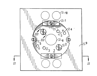
Figure 1 is a front view of a fixture box according to the
present invenkion;
Figure 2 is a view through line II-II of Figure 1:
Figure 3 is a view through line III-III of Figure l;
Figure 4 is a front view of an outlet box according to the
present invention;
Fi~ure 5 is a view through line V-V of Figure 4;
Figure 6 is a view through line VI-VI of Figure 4;


Referring now to Figures 1, 2 and 3, a hollow fixture box
B according to the present invention has a flat rear surface 7
for mounting directly against a wall surface. A pair of key-
hole apertures 4 are formed in the rear surface of the box, for
removable attachment of the box to a surface by screws which may
be screwed into framing studs or anchors in a wall or ceiling.
Holes 4 are accessi~le from the front o~ the box for tightening
of the said screws by provision of a large generally circular
aperture in the front surface 9 of the box. This aperture also
~o provides access to wiring within the box. The front and rear
surfaces of the box are joined by side panels 13, which form an
enclosure to accommodate access cable and cable connections etc.


Cable is led into and exits the box at knock-out~ 10 which
are provided at the top and ~ottom of the box. Adjacent cable
entry knock-outs 10, clamps 1 are provided on clamp mount6 B


. , .

.; -. :
- .~:. .. , .. : ~

' 2~2~2~

which are raised from the interior of the box. Cable which is
led into the box is slipped under clamps 1, and then screw ll is
tightened into clap mount 8 to secure the wire in place. Clamp
screw ll also functions as a ground screw. Additional ground
screws 2 are located on raised portions of the rear surface of
the box, as can be seen ~rom Figures l and 3O It will be
appreciated, then, that a metal plate will connect ground screws
2 and 11 if the box of the present invention is fabricated from
plastic. In khis regard, it will be understood that the box of
the present invention may be fabricated from any suitable
material, which will be a matter of choice for one skilled in the
art.


Additional screw holes 3 are provided for increased
flexibility in mounting the box of the present invention.
Moreover, an additional cable knock out 6 is pro~ided so that
additional cable may be led into the box.


On the front surface of the box, fixture bar hanger holes
5 are provided so that a standard light fixture bar h~nger may
easily be attached to the box of the present invention.


20Between the front and rear surfaces of the box there is a
hollow space to accommodate cable and wiring.


To install the box of the present invention, one need only
lead a cable through a wall, without the necessity of cutting a


", ,

~23~

hole in a wall for mounting a box therein. The appropriate cable
knock out is removed, and the cable led into the box and clamped
into place. The ground wire of the cable is screwed to a qround
connection 8, 2, in the box. The box is then securely fastened
by screws to the outer surface of the wall, and it is ready for
use. It will be appreciated that in the case of a brick or
masonry wall, installation requires only that a cable hole and
anchor holes be drilled through the wall. Extensive masonry
work is not re~uired to set the box in place. It is, however,
recommended to caulk around the installed box.


Referring now to the remainder of the figures, an outlet box
is shown. The structures and principles of it are substantially
as described abo~e. The only difference bein~ the size and shape
thereof, and the provision of an addit:ional access aperture 13
at the top and bottom of the box for accessing clamp screws 8.
As well, bar hanger screw holes are replaced with receptacle
atta~hment screw holes 12. Mounting holes 4 are not provided,
mounting being done via holes 3.


It will be appreciated that access apertures 13 will be
covered by a receptacle plate after a receptacle has been
installed in the box.


It is to be understood that the examples described above are

not meant to limit the scope of the present invention. It is
expected that numerous vari~nts will be obvious to the person


:., ~ . :.: .
.: : .: .- ::

.: .. : :,: .
. . : :. -
:: ~
': : , '~ .: .. : . :

2 ~ 2 ~ ~

slcilled in the electrical wiring apparatus design field, without
any departure from the spirit of the present invention. The
appended claims, properly construed, form the only limitation
upon the scope of the present invention.


: . :,; . .

Representative Drawing
A single figure which represents the drawing illustrating the invention.
Administrative Status

For a clearer understanding of the status of the application/patent presented on this page, the site Disclaimer , as well as the definitions for Patent , Administrative Status , Maintenance Fee  and Payment History  should be consulted.

Administrative Status

Title Date
Forecasted Issue Date 1998-02-03
(22) Filed 1990-10-30
(41) Open to Public Inspection 1992-03-19
Examination Requested 1994-01-12
(45) Issued 1998-02-03
Deemed Expired 2004-11-01

Abandonment History

There is no abandonment history.

Payment History

Fee Type Anniversary Year Due Date Amount Paid Paid Date
Application Fee $0.00 1990-10-30
Maintenance Fee - Application - New Act 2 1992-10-30 $50.00 1992-09-28
Maintenance Fee - Application - New Act 3 1993-11-01 $50.00 1993-10-18
Maintenance Fee - Application - New Act 4 1994-10-31 $50.00 1994-10-07
Maintenance Fee - Application - New Act 5 1995-10-30 $75.00 1995-10-13
Maintenance Fee - Application - New Act 6 1996-10-30 $75.00 1996-10-03
Final Fee $150.00 1997-09-09
Maintenance Fee - Application - New Act 7 1997-10-30 $75.00 1997-09-09
Maintenance Fee - Patent - New Act 8 1998-10-30 $75.00 1998-10-30
Maintenance Fee - Patent - New Act 9 1999-11-01 $75.00 1999-10-29
Maintenance Fee - Patent - New Act 10 2000-10-30 $100.00 2000-10-27
Maintenance Fee - Patent - New Act 11 2001-10-30 $300.00 2002-10-15
Maintenance Fee - Patent - New Act 12 2002-10-30 $100.00 2002-10-15
Owners on Record

Note: Records showing the ownership history in alphabetical order.

Current Owners on Record
STUMM, ERIC
Past Owners on Record
None
Past Owners that do not appear in the "Owners on Record" listing will appear in other documentation within the application.
Documents

To view selected files, please enter reCAPTCHA code :


To view images, click a link in the Document Description column. To download the documents, select one or more checkboxes in the first column and then click the "Download Selected in PDF format (Zip Archive)" or the "Download Selected as Single PDF" button.

List of published and non-published patent-specific documents on the CPD .

If you have any difficulty accessing content, you can call the Client Service Centre at 1-866-997-1936 or send them an e-mail at CIPO Client Service Centre.


Document
Description 
Date
(yyyy-mm-dd) 
Number of pages   Size of Image (KB) 
Claims 1997-04-29 2 62
Drawings 1997-04-29 2 43
Cover Page 1994-02-26 1 20
Abstract 1994-02-26 1 25
Claims 1994-02-26 2 55
Description 1994-02-26 6 222
Cover Page 1998-01-29 1 42
Representative Drawing 1998-01-29 1 8
Fees 1998-10-30 1 34
Fees 1999-10-29 1 26
Correspondence 1997-09-09 1 38
Fees 2000-10-27 1 26
Fees 2002-10-15 2 126
Fees 1997-09-09 1 38
Fees 1997-09-09 1 37
Prosecution Correspondence 1994-10-14 1 31
Examiner Requisition 1996-09-06 2 79
Prosecution Correspondence 1997-01-06 3 109
Office Letter 1994-03-01 1 69
Prosecution Correspondence 1994-01-12 1 26
Office Letter 1991-05-23 1 52
PCT Correspondence 1991-04-25 2 57
Fees 1996-10-03 1 44
Fees 1995-10-13 1 36
Fees 1994-10-07 1 38
Fees 1993-10-18 1 32
Fees 1992-09-28 1 30