Note: Descriptions are shown in the official language in which they were submitted.
~290~2
133152
SPRAY HEADS
The present invention relates to spray heads, to
tank-flushing assemblies incorporating one or more such spray
heads and to spray application equipment provided therewith e.g.
for use in agriculture, horticulture and forestry.
05 In order to decontaminate agrlcultural spray application
equipment after use, normally the spray tank must be filled to
the neck wlth water to rinse chemical solution from all internal
surfaces. The washing procedure may have to be repeated several
tlmes when changing to a different pesticide. As tractor mounted
sprayers commonly have capacities of 1500 litres or more, the
volume of contaminated washings generated can be substantial.
Where the washings must be sprayed out, this is wasteful of both
the land area required and the operators time.
UK Patent Application No. 8828270 discloses a tank-flushing
assembly in which only a fraction of the rinse water hitherto
required is sprayed over the inner walls of the tank in a
reclrculating flow. Reducing the amount of liquid in this way
effects a corresponding reduction ln the requlred capacity or
area of any d~sposal facility, and reduces the time needed to
clean out the tank(s).
Although such a system is perfectly adequate for smooth
walled tanks which are substantially free from lnternal
obstructions, most spray tanks contain one or more lnternal
hoses, as well as other obstructions like the filter basket etc.
Some designs, for example, have features moulded into the tanks
which cause channelling or separation of the down-wash from the
tank walls. In one such design, for example, a channel is
moulded around the waistline of the tank to locate a horizontal
mounting strap and the resulting protrusion inside the tank
interrupts the down-wash from the simple overhead spray heads so
that there is a risk of pockets of chemical residue belng left
behind underneath the protrusion.
.
. .
. . . : '
.
2 ~ 2
An object of the present invention is to provide an improved
spray head e g. for use in tank-flushing assemblies of the kind
disclosed in UKPA 8828270.
According to the present invention, a spray head includes a
05 flow passage for the liquid to be sprayed and a distributor
positioned to interrupt the flow of liquid from the flow passage
and operative to disperse a significant proportion of said flow
to the flow passage side of the distributor.
Conveniently, the distributor presents an inclined e.g. an
obliquely inclined, surface to the flow of liquid from the flow
passage.
Conveniently, the distributor is mounted for rotation about
an axis parallel to the flow of liquid from the flow passage.
Conveniently, when the distributor is mounted for rotation in
this way, then it is also provided with helically disposed or
functionally similar impeller surfaces so as to derive a
distributor-rotating reaction force from the flow of liquid
received from the flow passage.
Conveniently, the distributor is secured to, or formed with,
a hub portion mounted in a hollow support with the hub/support
clearance space providing the flow passage.
Conveniently, the clearance between the hub and its support
is such that the space:hub cross-sectional area ratio lies in the
range 0.29 to 0.50.
Specific embodiments of the present invention are intended
for use in flushing the spray tanks of agricultural spray
application equipment and liquid storage equipment e.g. bulk milk
tanks. These spray heads may either be fitted as part of the
original equipment or they may be supplied in kit form for
retro-fltting to existing equipment.
The invention also includes tank flushlng assemblies
incorporating one or more spray heads in accordance with the
present invention and spray application equipment or liquid
storage equipment provided with such assemblies.
~ , ;,-
- . .
' ,. : ,:
. .
:. . - .
2~2~92
An embodiment of the present invention will now be described
by way of example only with reference to the accompanying
drawings in which: ;~
Figure 1 is a part sectional side view of one form of spray
05 head in accordance with the present invention;
Figures 2 and 3 are plan views of the spray head distributor
and distributor support used in the spray head;
Figure 4 is a schematic representation of spray application
equipment using a tank-flushing assembly in accordance with the
present invention; and
Figures 5(a) to 5(d) show a scrap view of a modification of
the Figure 4 equipment and three vertical sectlons of the valve
used in that modification.
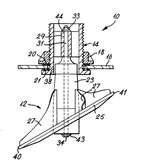
Thus referring first to Figures 1 to 3 of the drawing it
lS will be seen that the illustrated spray head unit 10 comprises a
distributor 12 which is rotationally mounted in an upper
support 14. This latter acts as a bulkhead fitting to fix
unit 10 in a suitable hole drilled into the tank top 16. The
support is secured in plane by a location nut 18 rubber seals
20 21 being included to provide a water-tight fitting.
As best seen from Figure 1 the d~stributor 12 ~nclùdes a hub
portion 23 an obliquely ~nclined circular distributor plate 25
and impeller blades provided by four curved vanes 27 extending
between the hub portion 23 and the distributor plate 25.
A central boss 29 (Figure 3~ of the support 14 locates a
steel pin 31 which acts as an axle for the rotating
distributor 12. The axle pin 31 is preferably small in diameter
e.g. 4 mm to minimise friction. Reference numerals 33 34
indicate lock nuts at either end of pin 31.
At its upper end the support 14 is tIreaded to pe mit
connection to a flush system pipework for the tank. As can be
seen from Figures 1 and 3; liquid from this system can pass down
through the three holes 36 provided around the boss 29 (Figure 3)
to flow through the passage provided by the annular hub/support
clearance space 38 (Figure 1). This has the effect of
.
.
.
. . - ' ... . .
.
' , ' .
.
~7~2
accelerating the liquid flow as it passes through the upper
support on its way to the distributor plate 25, and of spreading
the flow evenly around the distributor hub 23.
In practice, the value chosen for the annular clearance space
05 between the hub and its support should be such that the space:hub
cross-sectional area ratlo lies in the range 0.29 to 0.50. With
smaller clearances, the resulting end thrust on the
distributor 12 will inhibit its rotation while with larger
clearances the flow velocity will be reduced below what is
required to give an acceptable throw of spray from the rotating
distributor 12.
On striking the distributor plate 25, the direction of the
flow is turned to spread radially across the plate. The impeller
vanes 27 prevent flow from concentrating on the downhill edge 40
of the plate.
In operation, a proportion of the flow travels some distance
across the plate 25 before striking a vane 27. Much of this flow
then deflects to follow the vane to the periphery of the plate,
but some of the rinse liquid (especially that at the uphill
edge 41 of the distributor plate) is deflected upwards towards
the adjacent region of tank top 16. This ensures that the local
area of the tank wall around the spray head 10 is not missed.
In addition to redirecting the liquid flow as above
described, the four curved vanes 27 also act like turbine blades
to induce rotation of the distributor about its vertical rotation
axis. To facilitate this rotation by reducing the friction
forces present when the distributor is under thrust load, a nylon
washer 43 is included between the bottom end of the distributor
hub 23 and the lower retaining nut 34 on the pin 31. A similar
washer 44 is provided at the top end of the boss 29.
In a modification (not shown), the nut 34 and washer 44 are
replaced by a thick PTFE thrust washer attached to the axle 31 by
a split pin passing through both components. As an alternative
to the split pin, some sort of spring clip may be used instead to
secure the PTFE washer in place.
': , ~ ` ;--.-
~ ~ .
,~
- 2~29~2
-- 5 --
The distributor plate 2S can be inclined at any suitable
angle to the rotation axis of the distributor, the value chosen
in any particular case being necessar11y a compromise between
flow pattern depth and side thrust on the axle pin 31, both of
05 which increase as the plate angle to the distributor's rotation
axis decreases. The angle of 60 chosen for the illustrated
embodiment is a typical value where two such spray heads are to
be used in the manner of Figure 4 for the usual sort of spray
tanks currently in use on commercially available agricultural
spray application equipment.
Turning now to Figure 4 of the drawings, spray appllcation
equipment S0 comprises a spray boom 52, a tank 54 for the liquid
(herbicide etc.) to be applied by the boom, and a pump 56 for
moving liquid from the tank to the spray boom through a suction
lS filter 58, main control valve 60 and delivery filter 62.
Reference numeral 64 indicates the usual pressure guage while
reference numeral 66 indicates a conventional by-pass agitator
feed with its pressure relief valve 68. The tank 54 is top-
loaded through the usual inlet port filter 70.
As has already been explained above, once spraying has been
completed, the tank 54 may be partially filled with water for
rinsing purposes and in accordance with another aspect of the
present invention, a rinse recirculation line 72 7s tapped off
from the usual "spray-off" return line 74 and a suitable two way
valve is provided at 76. With valve 76 open, the return line 72
will operate in the usual way, but when valve 76 is closed,
liquid which would have returned through the valve direct to the
tank 54, is instead redirected via tapping 78 into the rinse
recirculation line 72.
At its upper end, the recirculation line is connected via a
T-junction 80 and two equal-length hoses 82,83 to two spray
heads 10 each as hereinbefore described and illustrated with
reference to the earlier Figures.
Thus, once spraying has been completed and the tank 54 has
been emptied of its original contents, the tank is filled about
.' . . ' . : '.'; . ................................. .
,
- .: . .- - . . . - -
2 ~ ~t~ 2
one tenth full with water. Then with valve 76 closed and the
main control valve 60 turned to its alternative position (rather
than to that illustrated in Figure 4) the pump 56 is used to
circulate rinsing water from the tank 54 along line 72 and back
05 through the spray heads 10 as above described. This process is
continued until the walls of the tank have been thoroughly rinsed
by the spray from spray heads 10 whereupon the one way valve 76
is again opened and control valve 60 is returned to its
illustratcd position to spray out the contaminated washings
through the noz~les on spray boom 52.
The illustrated spray head is intended to be applicable to
any spray tank and may be either fitted as original equipment
or supplied in k~t form for retro-fitting to existing equipment
without major modification (for example without fitting an extra
tank).
In a modification shown in the scrap view of Figure 5(a)
the valve 76 is omitted and the tappillg 78 is replaced by a
three-way valve 90 providing an L-shaped flow channel 92 in its
spherical valve member 94.
In between spray applications the control knob 96 is set as
shown in Figure 5(b) and the valve connects the spray-off
return line 74 directly to the tank 54 to promote agitation of
the spray liquid remaining in the tank. In this position the
rinse re-circulation line 72 is shut off by the valve to prevent
dribble from the spray heads 10.
When spraying has been completed and it is desired to rinse
the tank the valve member is rotated to the position shown in
Figure 5(d) so that the rinse water now in tank 54 can be
directed via return line 74 and re-circulation line 72 to the
spray heads 10.
Pilot holes 98 99 formed in the side walls of the flow
channel 9Z prevent the flow from line 74 from being interrupted
as the valve passes through the midway position shown in
Figure 5(c). Thi5 avoids the pressure pulse that would otherwise
result as the valve member 94 is rotated from one position to the
.
- . . .
other and the consequent blow-off of the push-fit hoses used for
lines 74 etc.
The princlpal advantage of the present invention e.g. over
the system of UKPA 8828270, is that a more efflcient flushlng of
05 the more complexly shaped spray tanks can be obtained than
hltherto. Thls is flrstly because rotating the dlrection of the
rinslng spray reduces the chance of missed areas, elther behind
obstructlons or where the flow is channelled, and secondly,
because part of the spray can be directed to the lower reglons in
the tank whlch may be masked from a slmple symmetrical overhead
spray. The present inventlon also shares with the system of
UKPA 8828270 the advantage over the prior art systems that
signlflcantly less tlme is required than with the conventional
fill-and-discharge rinslng technique previously employed.
Although ln the lllustrated tank-flushing assembly only two
spray heads according to the present invention have been used, lt
wlll be appreclated that in other situations, the assembly may
include only a slngle such spray head or it may lnclude three or
more such spray heads, lf deslred. In all such cases, the pump
or pumps used should preferably be able to supply the or each
such spray head with at least 40 litres per minute of the
flushing llquld.
.