Note: Descriptions are shown in the official language in which they were submitted.
- PHA 70062 2029~21
,, ~ .
MASS IJOADER MECHANISM AND METHOD
Technical Field of the Invention
This invention relates in general to optical
storage disk devices, and in particular to an apparatus
for ~toring, moving and loading a plurality of optical
S storage disks and method.
Backaround of the Invention
Electronic data storage devices such as magnetic
disk readers, optical disk readers and tape readers are
generally m~re efficient when provided with some type of
automated apparatus for inserting, removing and storing
the disks or tapes. In some cases, elevator type
devices such as are found in jukeboxes have been used to
load and unload the disks or tapes. Unfortunately, the
~ukebox type device is designed to maximize capacity
rather than efficiency. Thus, it is usually necessary
to go through an entire sequence of selecting from
storage, moving to a reader, loading into the reader,
reading, unloading and moving back to ~torage before a
different selection may be made. Additionally, a
jukebox type changing device is usually large and
complex with associated high cost. Thus in an
environment where high data productivity and low cost
are important, the elevator type device is inadequate.
One alternative to the elevator type device is
disclosed in U.S. Patent No. 4,271,489 to Siry; et al.,
June 2, 1981, and U.S. Patent No. 4,286,790, to Siryj et
al., September 1, 1981. In the Siry; patents, a
magazine rack holds a plurality of optical disks in a
vertical orientation. A changer, which travels parallel
to the magazine rack, secures one disk from the magazine
rack and transfers the disk to a reading position. The
changer moves along a ball screw to the proper position
2029221
. i
for selecting a disk to be used from the stationary
magazine. The changer secures the disk from the
magazine and places it in a change position while
travelling into alignment with the reader. The changer
then inserts the disk into the reader which scans the
data from the disk. Unfortunately, the Siry~ device is
complex with many moving parts and must be operated as a
complete unit in conjunction with a special reader.
Another type of automatic changer is disclosed in
U.S. Patent No. 4,S19,055 to Gilson, May 21, 1985. The
Gilson device comprises a carousel type cartridge
storage module. In the center of the module, a changer
rotates to select any one of the cartridges for reading.
After selecting and gripping a cartridge, the changer
moves the cartridge, in conjunction with a carrier to a
reader below the storage module for ~canning. Thus the
cartridges must be moved horizontally from a storage
position to a changing position and then vertically from
the changing position to a reading/scanning position.
The Gilson device, like the Siry~ device, is fairly
complex and must generally be operated as a complete
unit with an included reader. Thus there is a need for
a method and apparatus that is simple in operation and
may, if desired, be adapted for use with a variety of
Z5 reading devices.
Summarv of the I m ention
The present invention disclosed herein describes a
method and apparatus for storing, moving and loading a
plurality of optical storage disks which eliminates or
su~stantially reduces problems associated with prior
storing, moving and loading devices. The present
invention allows the storing, moving and loading of
optical storage disks with a relatively simple device
. .~
- 2029~21
.
constructed integrally with an optical reader or which
may be added to an existing optical disk reader, if
desired.
In accordance with one aspect of the invention, a
magazine stores a plurality of optical storage disks
each in a cartridge in a vertical and parallel
orientation. The magazine comprises a removable
container which may be transported as a separate unit
having open front and rear ends for inserting and
removing the cartridges. Linear slots are provided
along a bottom of the container for receiving an
upwardly protruding loading pin. The upwardly
protruding pin is connected to a cartridge loading
device which secures a single selected cartridge and
inserts the cartridge into an optical storage disk
reader.
The loading device comprises a lead screw which is
motor driven by a ~elt. A follower nut to which the
protruding pin i8 attached travels along the lead screw
as the motor turns the lead screw. A channel is
provided for the follower nut to travel within to
prevent rotation thereof. At both ends of the lead
screw, the follower nut fits into cutouts in the channel
to allow the follower nut and the protruding pin to
rotate out of contact with the cartridge. This rotation
at one end allows insertion of the cartridges into the
magazine as well as insertion of the magazine into a
device for moving the magazine. At the other end, the
rotation allows isolation of the reader from the loading
device (the reader contains anti-shock devices, whereas
the loading device does not).
The magazine hangs from a magazine carrier which is
driven by a moving device. After the magazine is loaded
into the carrier, a signal may be transmitted
2029221
,, .
electrically to the moving device to move the carrier
and thus the magazine in a direction perpendicular to
the cartridge loading device. When the correct
cartridge for loading is positioned over the loading
device, the moving device stops the magazine carrier and
the cartridge loading device is activated. The upwardly
protruding pin on the follower nut is rotated into a
slot in the optical storage disk cartridge, and, as the
lead screw drives the follower nut therealong, the
protruding pin takes the cartridge with it. After
- inserting the cartridge into the optical storage reader,
the follower nut is turned aside to remove the
protruding pin from the cartridge.
It is a technical advantage of the present
invention that optical storage disk cartridges may be
loaded in a vertical orientation into a reader without
complex mechanisms such as an elevator. It i8 also a
technical advantage of the present invention that a
magazine containing a plurality of optical storage disk
cartridges may be provided as an attachment to an
existing optical storage disk reader.
It is a further advantage in that the present
invention allows the use of a separate removable
magazine which may be easily transported. The present
2S invention is compact in design and compares favorably to
a juke box device of similar capacity. It is a still
further advantage of the present invention in that the
magazine may be removed from the loading device for
loading cartridges away from the optical reader. This
provides the ability to use one magazine while another
is removed for loading of different cartridges. The
magazine ~ay optionally be loaded while positioned in
the magazine carrier.
2029221
Brief Descri~tion of the ~rawinas
For a more complete understanding of the present
invention and for further advantages thereof, reference
i8 now made to the following Detailed Description taken
Sin conjunction with the accompanying Drawings in which:
FIG. 1 is an isometric view of an optical disk
reader incorporating the apparatus for storing, moving
and loading optical storage disk cartridges in
accordance with the preferred embodiment of the present
invention;
FIG. 2 is a sectional view along line 2-2 of FIG.
l;
FIG. 3 is an end elevation along line 3-3 of FIG.
2;
15FIG. 4 is a sectional view along line 4-4 of FIG.
2;
FIG. 5 is a sectional view along line 5-5 of FIG.
3;
FIG. 6 is a partial sectional view along line 6-6
of FIG. 4;
FIG. 7 is a partial exploded isometric view of the
magazine of the present invention:
FIG. 8 is an isometric view, partially cut-away, of
the magazine and transporter mechanism of the present
invention;
FIG. 9 is a sectional view along the line 9-9 of
FIG. 8;
FIG. 10 is a top plan view of a portion of the
magazine carrier;
30FIG. 11 is a partial isometric view of the top
slide of FIG. 10
FIG. 12 is a side elevation of the magazine
ejection assembly with a magazine loaded; and
.. , , ... ."~,. . ...
202922~
FIG. 13 is a side elevation of the magazine
ejection assembly with a magazine being ejected.
Detailed Descri~tion of the Invention
In FIGS. 1-13, like items are identified by like
and corresponding numerals for ease of reference.
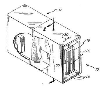
Referring first to FIG. 1, a mass loader constructed in
accordance with the preferred embodiment of the present
invention is generally identified by the reference
numeral 10. The mass loader 10 may be fixed by any
appropriate method to an optical storage disk reader
generally identified by the reference numeral 12. The
mass loader 10 allows the storing, moving and loading of
a plurality of optical storage disk cartridges 14.
The optical storage reader 12 is preferably of the
type which allows the simultaneous reading of both sides
of an optical disk. By combining the mass loader 10 of
the present invention with a dual side optical reader,
it i5 possible to eliminate the need for a complex and
bulky elevator. Although the preferred embodiment is
described for use with a dual side reader, it is to be
understood that use with other types of readers will
still allow some of the advantages herein disclosed.
The cartridges 14 are stored in a magazine 16 in a
parallel and vertical orientation with the magazine 16
depending from a magazine carrier 18. The magazine
carrier 18 moves the magazine 16 in a direction
indicated by an arrow 20, generally perpendicular to the
parallel orientation of the cartridges 14, as will be
subsequently described in greater detail.
The magazine 16 is positioned by the magazine
carrier 18 to allow loading of the cartridge 14, into
the optical disk reader 12. As will be subsequently
described in greater detail, one of the cartridges 14 is
2029221
.i
~elected by a cartridge loading apparatus 28 (FIG. 2)
and inserted into the reader 12.
Referring to FIG. 2, a cross-sectional view along
the line 2-2 of FIG. 1 ~5 shown. One of the cartridges
14 is shown in a load position properly aligned with the
optical reader 12. The reader 12 may be provided with
guide rails 22 and 24 to guide and hold the cartridge 14
within the reader 12. The reader 12 may also have a
drive motor and spindle assembly which is generally
indicated by the reference numeral 26. Upon insertion
of the cartridge 14 into the reader 12, the drive motor
and spindle assembly 26 provide rotational motion to a
disk (not shown) within the cartridge 14 in order to
obtain data therefrom.
The cartridge loading apparatus 28 is provided to
load the selected cartridge 14 into the reader 12. The
loading apparatus 28 comprises a first lead screw 30 and
a follower nut 32. The lead screw 30 i8 supported by a
bracket and channel assembly 34 ~only shown partially in
FIG. 2 for the sake of simplicity), as will be
subsequently described in greater detail. The lead
screw 30 is rotationally driven by any appropriate
method, such as a drive pulley 36, a drive belt 38 and a
motor 39 ~FIG. 3).
2~ To load the cartridge 14 ~nto the reader 12, the
magazine carrier 18 is positioned to place the selected
cartridge 14 in the loading position. A loading pin 40
on the follower nut 32 is rotated into a slot 42 in the
cartridge 14. The lead screw 30 then turns through the
action of the motor 39, the belt 38 and the pulley 36 to
drive the follower nut 32 therealong moving the
cartridge 14 with the pin 40. After the cartridge 14 is
loaded into the reader 12, the follower nut 32 is turned
to allow the loading pin 40 to be rotated out of the
2029221
slot 42 of the cartridge 14, as will be subsequently
described in greater detail. After the optical reader
12 has obtained the required data on the disk within the
cartridge 14, an unload sequence generally opposite the
S load sequence ~ust described is initiated.
A cartridge retaining assembly generally identified
by the reference numeral 44 i5 provided to hold the
cartridges 14 within the magazine 16. As will be
subseguently described in greater detail, the asse~bly
44 i5 biased toward the cartridge 14 to place a bar 46
within a slot 48 in the cartridge 14 directly opposite
the slot 42 previously described (thus allowing the
cartridges 14 to be loaded into the magazine 16 on
either end thereof). As the magazine 16 is loaded into
the magazine carrier 18, the bar 46 i6 removed from the
slot 48 (by means not shown in FIG. 2) allowing the
cartridges 14 to be inserted into and removed from the
magazine 16.
~he magazine carrier 18 is driven along a 6econd
lead screw 50 by a follower nut S2 which is fixed to a
top surface 54 of the magazine carrier 18 by any
appropriate method, such as welding. ~he lead screw 50
may be driven by any appropriate means such as a drive
belt 56 and a motor 58. A guide bar 60 is provided to
help balance and support the magazine carrier 18 during
its movement by the action of the lead screw 50. The
guide bar 60 travels through at least one pillow block
- 62 fixed to the top surface 54 of the carrier 18 and is
supported by sidewalls of a case 66 (FIG. 1) which
enclose the magazine carrier 18 and the magazine 16. To
place a cartridge 14 into the loading position, the
motor 58 drives the lead screw 50 causing the follower
nut 52 and the magazine carrier 18 to travel therealong,
2029221
thus moving the magazine 16 in the direction 20 (FIG. 1)
perpendicular to the cartridges 14.
Referring to FIG. 3, an end elevation along the
line 3-3 of FIG. 2 is shown in which the case 66 can be
seen to enclose the magazine carrier 18 and the magazine
16. The guide bar 60, which is supported by the
sidewalls of the case 66, helps guide the magazine
carrier 18 during its travel. In the preferred
embodiment, the guide bar 60 is interconnected to the
magazine carrier 18 by two pillow blocks 62. The
magazine 16 comprises a first sidewall 68, a second
sidewall 70, a top 72 and a bottom 74. Protrusions 76
extend toward each other from the top 72 and the bottom
74 of the magazine 16 to form guide channels 78
therebetween for receiving and guiding the cartridges
14.
In operation, a plurality of cartridges 14 are
loaded into the magazine 16 which may or may not yet be
loaded into the magazine carrier 18. Each cartridge 14
is fit into one of the guide channels 78 and slidably
inserted until the slot 48 is aligned with the bar 46
(FIG. 2). The cartridge retaining assembly 44 which was
lifted to remove the bar 46 from obstructing the
insertion of the cartridge 14 is released to insert the
bar 46 into the slot 48. This sequence is repeated
until as many of the channels 78 are filled as desired
with cartridges 14 which are then retained within the
magazine 16 by the bar 46. The magazine 16 is then
loaded into the magazine carrier 18, as will be
subsequently described in greater detail.
Referring to FIG. 4, a cross-sectional view along
the line 4-4 of FIG. 2 is shown. The lead screw 50
which drives the magazine carrier 18 and the ~agazine 16
perpendicular to the cartridges 14 is rotationally
2029221
attached at opposite ends thereof to the case 66. The
drive motor 58 drives the belt 56, a drive pulley 80 and
the lead sorew 50 which causes the follower nut 52 to
travel therealong. Since the follower nut 52 is fixed
to the top surface 54 of the magazine carrier 18, the
~agazine carrier 18 travels therewith.
The follower nut 32 of the cartridge loading
apparatus 28 is shown with the loading pin 40 inserted
into an opening 82 which is centrally located between
the protrusions 76 in the guide channels 78 to allow the
follower nut 32 to pull a cartridge 14 therealong. The
bracket and channel assembly 34 has a first sidewall 84
and a second sidewall 86 between which the follower nut
32 runs. As the lead screw 30 turns, the follower nut
32 runs therealong within the bracket and channel
assembly 34 which prevents the follower nut 32 from
turning aside.
As can also be seen from FIGS. 3 and 4, the~e is
sufficient room between the ~idewalls of the case 66 to
allow the magazine 16 to move to place each of the
cartridges 14 into the loading position directly over
the lead screw 32 regardlesæ of their position within
the magazine 16. The motor 58 is therefore reversible
to drive the magazine 16 and the magazine carrier 18
back-and-forth along the lead screw 50.
Referring to FIG. 5, a cross-sectional view along
the line 5-5 of FIG. 3 is shown. The protrusions 76 run
the length L of the magazine 16 to form the guide
channels 78 therebetween. The first sidewall 68 and the
second sidewall 70 of the magaz~ne 16 form with the
protrusions 76 the exterior most guide channels 78. The
openings 82 are formed within the guide channels 7B
between the protrusions 76 running the length thereof to
allow removal and insertion of the cartridge 14 by the
2029221
.
loading pin 40. Proximate the rear edge 88 of the
magazine 16 there are a plurality of sensors 90 which
provide data to a controller (not ~hown) indicating
whether a cartridge 14 i8 present within the guide
channels 78. Proximate the sensors 90 are retaining
~prings 92 which help keep the cartridges 14 within the
magazine 16 without preventing insertion or removal
thereof when the bar 46 i5 removed ~rom the slots 48.
Referring to FIG. 6, a partial cross-sectional view
along the line 6-6 of FIG. 4 is shown with the cartridge
14 fully inserted into the magazine 16 and in the
loading position. The slot 42 in the cartridge 14 i5
aligned with the loading pin 40 of the follower nut 32.
The ~ollower nut 32 is driven by the lead screw 30 which
15 ~upported by the bracket and channel assembly 34.
The lead screw 30 is driven by the drive pulley 36 fixed
to an end thereof which ~ 5 in-turn driven by a drive
belt 38. Thus, the cartridge 14 i5 in the load position
with the loading pin 40 positioned to pull/push the
cartrldge 14 as the lead screw 30 drives the follower
nut 32.
The sensor 90 and the retaining spring 92 are
located on the rear edge 88 of the magazine 16. The
spring 92 is constructed and arranged to provide a
slight retaining force on the cartridge 14 which may be
easily overcome by the lead screw 30. The sloped sides
of the spring 92 allow the cartridge 14 to push the
spring 92 into a recess 94 therebelow as the cartridge
14 moves in either direction.
Referring to FIG. 7, a partially exploded isometric
view of the magazine 16 and the cartridge loading
apparatus 28 is illustrated. The cartridge retaining
assembly 44 comprises a handle 96 fixed to the bar 46.
A spring 98 is attached between each end of the bar 46
11
- 2029221
and a portion of the sidewalls 68 and 70 of the magazine
16 to bias the bar 46 in the direction of an arrow 100.
Thus, when a cartridge 14 is inserted within the
magazine 16, the bar 46 will normally secure the
cartridge 14 therein.
The cartridges 14 are slidably received within the
magazine 16 within the guide channels 78. The sensors
90 indicate whether a cartridge 14 is positioned within
the magazine 16 and the retaining spring 92 assists in
holding the cartridges 14 within the magazine 16 once
loaded into the magazine carrier 18. A cutout 102 is
formed through each protrusion 76 and the bottom 74 of
the magazine 16 to allow passage of the loading pin 40
therethrough. Similarly, cutouts 104 are formed through
the protrusions 76 distal the cutouts 102 to allow
movement of the magazine 16 without interference from
the pin 40 subsequent to loading a cartridge 14.
one of the cartridges 14, for example, cartridge
14A is shown as being partially moved from the storage
position as shown in phantom lines. ~he pin 40 is
within the slot 42 to pull/push the cartridge 14A as the
follower nut 32 is driven along the lead screw 30.
The lead screw 30 is driven by the motor 39 through
the pulley 36 by the belt 38. As the lead screw 30 is
turned, the follower nut 32 is driven therealong. The
bracket and channel assembly 34 has a first sidewall 84
and a second sidewall 86 within which the follower nut
32 travels. A notch 106 is formed in the first sidewall
84 proximate the pulley 36 to allow the follower nut 32
to be rotated out of contact with the magazine 16 to
allow insertion thereof into the magazine carrier 18 as
well as to allow insertion of individual cartridges 14
into the magazine 16. A notch 108 is similarly located
at the opposite end of the assembly 34 in the second
12
` 2029221
wall 86 to allow the follower nut 32 to rotate the pin
40 out of contact with the cartridge 14A after loading
thereof into an optical reade, 12, thus isolating the
cartridge 14A from the mass loader 10.
A door 120 is rotatably attached by a friction
clutch 121 to the end of the lead screw 30 distal the
pulley 36. When the lead screw 30 is driven in a
clockwise direction as indicated by an arrow 122, the
door 120 is rotated 90- in the clockwise direction 122.
Thus, during loading of the cartridge 14A, the door 120
is rotated away from its normal position blocking the
entrance to the optical reader 12 as shown in Fig. 7.
After removal of the cartridge 14A, the door 120 is
allowed to rotate 90- in a counter-cloc~wise direction
by the lead screw 30 to block the entrance to the
optical reader 12. The door 120 prevents the accidental
insertion of a cartridge 14 into the reader 12 when
loading the magazine 16 while installed in the carrier
18.
The case 66 is provided with a lip (shown only
partially at 65) projecting upwardly from the bottom 67
on an end distal the motor 39. The lip 65 may be formed
by bending a portion of the bottom 67 upwardly to
provide a stop for all but the center cartridge 14 in
the magazine 16. A cut-out must be provided in the lip
65 to allow the cartridge 14 in the loading position to
be loaded into the reader 12 with the door 120 providing
a stop for the loading position cartridge 14 (unless the
cartridge 14 is actually being loaded into t,he reader
12)-
Referring to FIG. 8, the magazine 16 is positioned
for insertion into the magazine carrier 18 which has a
general U-shape. The follower nut 32 is rotated into
the notch 106 to prevent the loading pin 40 from
13
2~29221
. .
obstructing the insertion of the magazine 16. Rails 110
on the magazine 16 are placed into alignment with
~langes 112 in the magazine carrier 18 to insert the
~agazine 16 therein. Guide wheels 114 are provided
along the flanges 112 to support and allow movement of
the magazine 16. As the magazine 16 is inserted into
the carrier 18, the pins 116 which are extensions of the
bar 46 of the cartridge retaining assembly 44 come into
contact with a portion of a magazine ejection assembly
generally identified by the reference numeral 118, as
will be subsequently described in greater detail. The
assembly 118 lifts the pins 116 against their downward
bias to remove the bar 46 from the slot 48 in the
cartridges 14. By removing the bar 46 from the slots
48, the follower n~t 32 and loading pin 40 may propel
the cartridges 14 into the optical reader 12.
Referring to FIG. 9, a view of the assembly 44
along the line 9-9 of Fig. 8 i8 shown. ~he assembly 44
compr~ses the handle 96 fixed to the bar 46 by any
appropriate method such as bolts 124. The pins 116
project through the sidewalls 68 and 70 tonly 68 shown)
of the magazine 16. The spring 98 normally biases the
bar 46 downwardly as indicated by the arrow 100 in order
to fit into the slots 48 in the cartridges 14. Upon
engagement with a portion of the magazine ejection
assembly 118, the pins 116 are pushed upwardly as
indicated by an arrow 128 to release the cartridges 14
for loading into the reader 12.
Referring simultaneously to Figs. 10, 11, 12 and
13, the magazine ejection assembly 118 is shown in
greater detail. Referring first to Fig. 10, a top slide
130 is positioned on a top curface 132 of the magazine
carrier lB. The top slide 130 preferably comprises a
generally rigid, metallic substance and i6 formed with
14
2029221
slots 134 therein. The slots 134 are slidably received
by pins 136 which are fixed to the top surface 132. A
~andle 138 is provided to allow an operator ~o ~lide the
top slide 130 in a direction indicated by an arrow 140
along the slots 134 from the normal position as shown in
Fig. 10 to the position as shown in Fig. 11.
The normal position for the top slide 130 is
maintained by a pair of spring biased pivot arms 142.
The pivot arms 142 press against L-Shaped projections
144 on the top slide 130 due to a spring 146 (Fig. 11).
When an operator pushes the handle 138 to slide the top
slide 130 in the direction 140, the projections 144
force the pivot arms 142 to pivot against the bias of
the spring 146 into the position as shown in Fig.ll.
Referring to Figs. 12 and 13, the pivot arms 142
are shown in operation. Fig. 12 illustrates the normal
spring biased position for the pivot arms 142 (only one
of which is shown). In the normal position, the pivot
arm 142 is in a generally vertical orientation about a
pivot pin 153. A first arm 148 abuts and holds a spring
loaded ejector 150 against slide pins 152 which are
fixed to the carrier 18. A 6econd arm 154 secures a
magazine retaining pin 156 (see Fig. 8) by an extension
158 thereon.
The ejector 150 has slots 160 therein to allow
sliding relative to the pins 152. The ejector 150 is
biased in a direction indicated by arrow 16~ by a
tension spring 164 fixed between the carrier 18 and a
protrusion 166 on the ejector 150. Due to the first arm
148 on the pivot arm 142, the ejector 150 is pushed
against the bias of the spring 164 into the pins 152 as
shown in Fig. 12.
An ejector flange 167 is formed on an end of the
ejector 150 distal the arm 148. The flange 167 extends
2029221
... ..
outwardly with reference to the plane of the paper to
contact a front edge 168 of the magazine carrier 16
which would also extend outwardly from the plane of the
paper.
A cutout 170 in the pivot arm 142 is provided to
receive the pins 116 of the bar 46. A sloped portion
172 allows the pins 116 to slide into the cutout 170
which is arranged to hold the bar 46 out of the slots 48
in the cartridges 14 as previously described above.
Thus, as the magazine 16 is loaded into the carrier 18,
the pins 116 hit the sloped surface 172 and slide
upwardly into the cutouts 170 to release the cartridges
14 for loading into the reader 12.
To eject the magazine 16, an operator pushes the
handle 138 in the direction 140 ~Fig. 13) to move the
top slide 130 against the pivot arms 142. The L-Shaped
projections 144 force the pivot arms 142 to pivot about
their pivot pins 153 in a direction indicated by arrow
176. The pivoting of the arms 142 causes the first arms
148 to move away from and release the ejectors 150. The
ejectors 150 are thus free to slide in the direction 162
along the slots 160 against the pins 152 due to the
tension in the springs 164. Additionally, the pivoting
of the arms 142 causes the cecond arms 154 to release
the magazine retaining pins 156. $hus, as the ejectors
150 slide in the direction 162 and the ejector flanges
167 push against the front edge 168 of the magazine 16,
the magazine 16 slides out of the carrier 18.
The ejector 150 remains in the spring biased
position as shown in Fig. 13 until the magazine 16 is
reloaded. During the reloading process, the front edges
168 of the magazine 16 push against the flanges 167
moving the ejectors 150 into the position as shown in
Fig.12. The movement of the ejectors 150 allows the
16
2~29221
pivot arms 142 to pivot about pins 153 due to the
biasing of the springs 146 and lock the ejectors 150 by
the first arms 148. The pivoting of the pivot arms 142
also catches the retaining pins 156 between the second
arms 154 and the extensions 158 as shown in Fig. 12 to
lock the magazine 16 in place. The pivoting of the arms
142 forces the top slide 130 into the position as shown
in Fig. 12. As the magazine 16 approaches the fully
inserted position, the pins 116 slide up the sloped
portions 172 into the cutouts 170 to release the
cartridges 14 from the arm 46. The mass loader 10 is
thus loaded and ready to reposition as reguired for the
loading of cartridges 14 into the reader 12.
In operation, at least one optical storage disk
cartridge 14 is slid into the magazine 16. The
cartridge 14 fits within the opening 82 between the
protrusions 76 in the magazine 16. The cartridge
retaining assem~ly 44 must be raised to allow each
cartridge 14 to be fully inserted into the magazine 16
and then lowered to loc~ the cartridge 14 therein. The
sensors 90 are provided in the magazine 16 to indicate
whether a cartridge 14 is present therein.
The magazine 16 is then loaded into the carrier 18
by matching the rails 110 with the flanges 112. As the
magazine is propelled into the carrier 18, the rails 110
easily ride on the guide wheels 114. The magazine 16 is
firmly held in place by the second arm 154 and the
magazine retaining pin 156. The bar 46 is removed from
the slots 48 in the cartridges 14 due to the action of
the pins 116 against the sloped portions 172 of the
pivot arms 142.
The magazine carrier 18 moves along the second lead
screw S0 to position the proper cartridge 14 for loading
into the reader 12. To load the cartridge 14, the
17
2029221 ,
first lead screw 30 is driven by the motor 39. As the
lead screw 30 turns, the follower nut 32 travels
therealong. Due to the loading pin 40 which is fixed to
the follower nut 32, a cartridge 14 is propelled into
the reader 12.
Upon completion of the scanning of material stored
within the cartridge 14, the follower nut 32 and loading
pin 40 pull the cartridge 14 from the reader 12 back
into the magazine 16. Based on an electrical signal
from an external source, the magazine 16 can then be
moved by the carrier 18 to place a different cartridge
into the loading position over the lead screw 30.
Thus, the present invention provides a relatively
simple device that allows the use of multiple disks
lS without the need for an elevator. The magazine herein
described is removable from the mass loader allowing
easy transportability. Cartridges may be inserted into
the magazine while the magazine is separated from the
magazine carrier or while hanging therefrom. Thus,
magazines may be easily replaced as units, thereby
increasing operational flexibility of the optical
storage disk reader.
Although the present invention has been described
with respect to a speciic preferred embodiment thereof,
various changes and modifications may be suggested to
one skilled in the art, and it is intended that the
present invention encompass such changes and
modifications as fall within the scope of the appended
claims.
.. .. . .