Note: Descriptions are shown in the official language in which they were submitted.
- 1 -
TITLE: A WATER-ACTIVATED SURVI~JAL LAMP UNIT AND AN
IMPROVED WATER SENSING SGdITCH THEREFOR
FIELD OF THE INVENTION
~'he present invention relates to a water-activated
survival lamp unit for mounting to .a flotation device such
as a life jacket ox a life raft. More particularly, the
invention relates to a survival lamp unit having an
improved fluid-sensing switch which does not require a
continuous contact with a coherent body of water for
operating the light source of the survival lamp unit.
BACKGROUND OF THE INVENTION
Most recently developed survival lamp units for use
an personal flotation devices, such as inflatable life
vests, require a fluid sensing sw itch closing an electric
circuit between a battery and a light source when in
contact with a coherent mass of water. A typical fluid
sensing switch comprises a pair of electric terminals
impressed with a certain voltage potential. When in the
dry state, the impedence between the terminals is very
high and the current allowed to circulate is virtually
nil. However, when wet, the impedence is dramatically
reduced establishing an electrical path which sets a
simple transistor circuit in the conduction state, closing
the electric circuit between the battery and the light
source.
A major drawback of this type of fluid sensing
switches is the requirement to maintain the electric
terminals continually immersed in water to obtain a steady
operation of the light source. Any discontinuance in the
electrical path between the terminals will extinguish the
light source. Consequently, when used on a life vest or
on another type of flotation device, the fluid sensing
switch and the light source of the survival lamp unit must
be physically separated to locate these components below
and above the water line respectively, for a proper
operation. This requirement complicates the construction
of the life vest because the manufacturer must provide a
routing for the cable interconnecting the two components,
an underwater pocket to hold the f:Luid sensing switch and
in addition, the likelihood of lamp failure is increased
because of possible leaks at the cable/component
junctions.
O$JECT AND STATEMENT OF THE INVENTION
An object of the present invention is a survival lamp
unit for use on an emergency flotation device, with a
fluid sensing switch which does not require a continuous
immersion into a coherent mass of water to properly
operate the survival lamp unit.
- 3 -
In one aspect, the present invention provides a
water-activated survival lamp unit for mounting to an
emergency flotation device slightly above the water line,
the survival lamp unit comprising:
- a hermetically sealed light transmissive housing;
- a light source mounted in tine housing;
- a battery mounted in the housing, the battery being
in an electrical circuit with the 7light source to actuate
same when the electrical circuit is in a closed condition;
- a water-sensitive actuator in said electrical
circuit, including a pair of electric terminals extending
outside the housing in a spaced apart relationship, the
water-sensitive actuator being responsive to a momentary
electrical path established between the electric terminals
through a coherent body of water t,o close the electrical
circuit for a predetermined time period largely exceeding
the duration of the electrical path, periodic water
splashing of the electric terminals allows to re-establish
at intervals the electrical path, each electrical path
occurence triggering the water-sensitive actuator to
effect closure of the electrical circuit for an additional
time period.
The major advantage of this arrangement is the
possibility to mount all the components of the survival
lamp unit inta a single hermeti<:ally sealed container
exposing to the exterior only the electric terminals of
- 4 -
the fluid sensing switch. Accordingly, the construction
of the emergency flotation device is simplified since
there is no longer a necessity to provide a cable routing
and a packet for the fluid-sensing switch. In addition,
the manufacturing costs of the survival lamp unit can also
be somewhat reduced because the cable and the associated
gasketing is eliminated.
Another important advantage is the possibility to
easily test the survival lamp unit without wetting or
disassembly of the device. To effect the test procedure,
it suffices to bridge the electric terminals of the fluid
sensing switch to artificially establish therebetween the
electrical path. This may actually be done by touching
the terminals with a wet hand or with any other type of
conductor that will reduce the impedance below the trigger
level.
In a preferred embodiment, the water-sensitive
actuator comprises a charge storage device, such as a
capacitor, driving a current-controlled switch serially
connected between the battery and the light source. In
operation, the battery continuously impresses a certain
voltage across terminals of the wai.,er-sensitive actuator.
When an electric path is established therebetween, the
resulting electric current chargfes the capacitor and
simultaneously commands closure of the current-controlled
- 5 -
switch, turning on the light source. Discontinuance of
the electric path between the terminals will not result in
an immediate opening of the current-controlled switch
because the capacitor will continue' to supply the current
required for the switch to remain i:n the closed condition.
Ultimately, the current-controlled switch will open when
the capacitor is depleted, deactiv<~ting the light source.
To provide a more or less steady operation of the light
source, it suffices to momentarily reestablish the
electrical path between the terminals of the water-
sensitive actuator in order to regenerate the charge of
the capacitor. In practise, this occurs when the survival
lamp unit is mounted on an inflatable life vest or on a
life raft, in proximity to the water line. The survival
lamp unit is subjected to a continuous water splashing
permitting to regenerate the charge of the capacitor on a
regular basis, thus maintaining the light source in
operation.
In a variant, a fluid absorbent composition may be
provided between the terminals so when wet, it will
provide a continuous electrical path therebetween. This
embodiment is particularly advantageous for applications
which require the survival lamp unit to operate when the
device is raised considerably above the water line or so
located that it cannot be reached by water splashes. A
practical example is a situation where a person wearing a
- 6 -
life vest is lifted from the wager into a life raft.
Without the fluid absorbent composition, the survival lamp
on the life vest will cease to oper<~te shortly thereafter.
In another variant, the survival lamp unit is
provided with a flashing light source. The advantage of
this arrangement resides in the reduction of the power
consumption of the light source, i:hus allowing to use a
brighter light source without the necessity to increase
the capacity of the battery.
BRIEF DESCRIPTION OF THE DRAWINGS
- Figure 2 is a perspective view of a life vest
equipped with a prior art survival lamp unit;
- Figure 2 is a perspective view of a life vest
provided with a survival lamp unit according to the
present invention;
- Figure 3 is a perspective view of the survival lamp
unit according to the invention;
- Figure 4 is a bottom plan view of the survival lamp
unit according to the invention;
- Figure 5 is a sectional view taken along lines 5-5
in Figure 4;
- Figure 6 is a perspective view of the survival lamp
unit according to a variant; and
- Figure 7 is a schematical diagram of the electrical
circuit of the survival lamp unit according to the
invention.
DESCRIPTION OF ~#, PREFERRED EMBODIMENT
Figure 1 depicts a person in the water maintained
afloat by a life vest provided with a prior art survival
lamp unit. The survival lamx> unit is identified
comprehensively by the reference numeral 10 and it
comprises a light source 12 mounted to a flexible tab 14
on the life vest, operated by a dry-cell battery (not
shown in the drawings) mounted in a water-proof housing 16
and connected to the light source 12 by an electrical
cable 18. The housing 16 also receives a fluid sensing
switch whose function is to automatically actuate the
light source 12 by closing the circuit with the battery
when the housing 16 is immersed in an electro-conductive
fluid such as water.
_$_
To operate the light source 12 in a steady fashion,
the fluid sensing switch in the' housing 16 must be
continually submerged, which necessitates to locate the
housing 16 in the lower portion of the life vest, below
the water line. On the other hand, the light source 12
must at all times remain above the water line to be
visible, necessitating a physic<~l separation of two
components of the survival lamp unit 109 which is
undesirable because it requires a special life vest
construction.
The survival lamp unit according to the invention,
depicted in Figure 2 is shown attached to a life vest.
fihe survival lamp unit is a considerable improvement over
the prior art device described above because all the
components of the lamp unit are mounted into a single
housing. Accordingly, the sole resquirement for mounting
the survival lamp unit to the life vest is to provide the
tab 10 or any other equivalent supporting structure,
without the necessity of a pocket tv hold the battery and
the fluid sensing switch and a routing for an electrical
cable.
The structure of the survival lamp unit according to
the invention will now be described in Figures 3 to 7.
The survival lamp unit, identified comprehensively by the
reference numeral 20, comprises a hermetically sealed
- g _
housing 22 made preferably of plastic material including
a dome-shaped transparent cover 24 terminating with an
outwardly extending flange 26. Immediately above the
flange 26 are provided a plurality of equidistant locking
teeth 28 which serve in conjunction with the flange 26 to
maintain the survival lamp unit 24 captive on a flexible
sheet-like material such as the mounting tab 10 of a life
vest, as it will be explained in detail hereinafter. Each
locking tooth 28 is shaped to pre ent a ramp surface 30
terminating with a locking face 32 in a spaced apart
relationship and parallel to the flange 26.
The bottom portion of the housing 22 includes a cup
shaped opaque base 34 displaying a radially outwardly
extending socket 36 receiving in a tight fit the flange
26. The continuity of the circular configuration of the
socket 36 is disrupted at a single location, for providing
a U-shaped pocket 38 to receive an electric terminal 40.
The bottom face of the cup-shaped base 34 is disc-shaped
displaying a central opening 42 receiving the projecting
terminal 44 of a dry-cell lithium type battery 46.
All the mating surfaces between the dome-shaped cover
24 and the cup-shaped base 34 are permanently sealed with
epoxy glue in order to render the housing 22 water-proof.
More specifically, epoxy glue is applied between the
flange 26 and the socket 36 and ~>eripherally around the
- 10 -
terminals 40 and 44. Care should b~e taken not to entirely
encapsulate the terminals so that at least a portion of
their metallic surface remains exposed to the exterior.
During the manufacturing process of the survival lamp
unit 20, it may be desirable to permit the lamp unit to be
handled before the epoxy glue has been cured, in occurence
for placing the lamp unit in individual packages
immediately after the assembly procedure has been
completed. At this end, a positive locking system is
provided between the transparent cover 24 and the base
member 34 preventing any relative movement between these
components, allowing the epoxy glue to cure even during
handling of the lamp unit. Th.e positive mechanical
locking system, best shown in Figure 4, is a series of
locking teeth 48 downwardly projecting from the flange 26
and fitting in individual locking recesses 50 formed on
the socket 36. The locking teeth 48 are of known
construction, each tooth comprising a camming face and
ending with a locking surface, similar to the
configuration of the locking teeth 28 described above.
During the installation of the transparent cover 24 on the
cup-shaped base member 34 the locking teeth 48 yield
somewhat during the penetration o:E the flange 26 in the
socket 36 as a result of their carnming surfaces coming in
sliding contact with the edges of the respective recesses
50. Once the locking faces of the teeth 48 have cleared
- 11 -
the edge of the respective recesses 50, the teeth recover
their original position preventing an unwanted removal of
the cover 24.
The battery 46, in addition to providing the
electrical power far operating the survival lamp unit 20,
constitutes a supporting structure for some internal
components of the device. The battery 46 is rigidly held
in the housing 22 by virtue of the adhesive mounting of
the terminal 44 in the opening 42. Accordingly, the
battery 46 is prevented to longitudinally move or tilt in
the housing 22. On the top end of the battery 46,
constituting the other terminal of. the battery which has
a planar configuration, is seated an insulating disc 52
carrying a light source 54 such <~s a small incadescent
lamp. The disc 52 is essentially a lamination, comprising
a plastic material core sandwiched between two thin copper
layers, of a type similar used for making circuit boards.
The copper layers are all etched e~:cept at two small spots
on the top surface of the disc 52 so that the terminals of
the light source 54, numbered 56 <~nd 58 respectively may
be soldered thereto, at 50 and 62. A rigid conductor 64
is connected between point 62 and the terminal 40 and a
similar rigid conductor 66 is pulled between the paint 60
and a circuit board 68 containing all the solid-state
electronic components of the lamp unit and being rigidly
mounted to the cup-shaped base member 34. Tt will be
- 12 -
appreciated that in addition to their current channelling
function, the conductors 64 and 6F~, along with the disk
52, form a strap which further secures the battery against
movement in the housing 22.
The operation of the survival lamp unit 20 will now
be described in connection with Figure 7 which illustrates
a schematical diagram of the :light unit electrical
circuit. At all times, the battery impresses a certain
voltage across outside terminals 40 and 42. The irnpedence
between these terminals being virtually infinite, no
current is allowed to circulate and the battery remains in
a fully charged condition. When an electric path is
established between the terminals 40 and 44, even be it
small, such as when dipping the terminals into a coherent
body of water, the resulting electric current passing
between the terminals through the fluid medium will charge
a capacitor 70, simultaneously turning on a solid-state
current-controlled switch 72 comprising a pair of cascaded
transistors Q1 and Q2. Current fT_owing through the base
terminal of Q1 sets the transistor in a conduction state
which injects current in the base 'terminal of Q2, causing
Q2 to conduct, whereby an electrical current can flow from
the battery 46 through the lamp 54. If the electrical
path between the terminals 40 and 44 is disrupted, the
capacitor 70 will nevertheless maintain the switch 72 on
by supplying enough base current through transistor Q1 to
- 13 -
maintain same in the conduction state. Ultimately, the
switch 72 will open When the capac=itor will be depleted.
When fully charged, the capacitor 70 may provide
several minutes of running time for the switch 72. The
circuit may be reactivated for an additional time period
by momentarily establishing an electric path between the
terminals 40 and 44 in order to charge again the capacitor
70.
By enlarging the size of the: capacitor, the self-
sustained running time of the survival lamp unit 20 is
increased at the expense of a longer capacitor charging
time. E'or applications where the Electrical path between
the terminals 40 and 44 can be maintained for longer time
periods, in the order of several seoonds, a larger
capacitor can advantageously be used to space the
recharging cycles necessary to maintain the lamp 54
continuously in operation.
When the life vest is worn by an individual in the
water, the survival lamp unit 20 extends slightly above
the water line, typically a fe;w inches. When the
individual moves around slightly, water is projected
against the housing 22 of the survival lamp unit 20,
establishing the electrical path between the terminals 40
and 44. As explained earlier, this electrical path
.. erg
- 14 -
occuring momentarily will actuate t;he light source 54 for
a predetermined time period. However, considering that
the water splashing will project water periodically on the
housing 22, this electrical path w~'.11 be reestablished at
intervals, in the overall, allowing the light source 54 to
operate in a continuous fashion.
When not in use, the survival lamp unit can be very
easily tested, simply by creating artificially the
electrical path between the terminals 40 and 44. This may
be achieved by touching with a wE~t hand both terminals
simultaneously or with any other conductor device. The
light source 54 will then be actuated for a predetermined
period of time and when the capacitor 70 is discharged,
the light source will turn off automatically. This is
particularly advantageous because the lamp unit may be
tested very rapidly without the necessity of opening the
housing 22 nor performing complex manipulations. When a
large number of lamp units must be tested, this feature
permits to complete rapidly the te.~ting procedure, easily
identifying the faulty units.
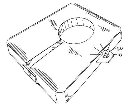
Referring back to Figure 2, the survival lamp unit 20
is installed on the tab 10 of a life vest simply by
sliding the cover 24 into the circular opening (not shown
in the drawings ) normally provided on the tab 10 . When
the sheet-like material of the tab 10 reaches the fingers
- 15 -
28, the ramp surfaces 30 thereof spread outwardly the
material allowing the transparent; cover 24 to further
penetrate in the tab, until the sheet-like material slides
past the locking fingers 28, abuting against the flange 26
and recovering its original shape, whereby remaining
captive between the flange 2G and t;he locking fingers 28.
In a variant illustrated in Figure 6, the location of
the terminals 40 and 44 has been changed, the terminals
now being located closer to one another and a string of
fluid absorbent medium 72 looped around the terminals in
physical contact therewith. The string of fluid absorbent
medium 72 may be of any composition such as cotton, wool
batt or any other type of fabric having the ability to
absorb and retain water between its fibers. When the
terminals 40 and 44 are immersed into an electro-
conductive fluid, and then withdra'an therefrom, the fluid
absorbing medium 72 will maintain the electrical path
between the terminals through the ;small quantity of fluid
remaining in the material. In this embodiment, the
capacitor 70 is maintained in a fully charged condition
until the fluid absorbing medium i;s dry so that the light
source 54 may continue to operate for long time periods
without the necessity of periodically recharging the
capacitor.
- 16 -
In another variant, the survival lamp unit 20 may be
provided with a flashing light souo:ce which has a smaller
power consumption comparatively i~o a continuous light
source, whereby allowing to use a brighter light without
increasing the capacity of the battery.
The circuit to obtain the light flashing will rat be
described because it is of known construction. Suffice it
to say that it is incorporated in the diagram of Figure 7r
serially between Q2 and the light source 54. The flashing
circuit is actuated when Q2 is set in the conduction
state.
The above description of preferred embodiments of
this invention should not be interpreted in any limiting
manner since these embodiments may be refined and varied
in several ways without departing from the spirit of the
invention. The scope of the invention is defined in the
annexed claims.