Note: Descriptions are shown in the official language in which they were submitted.
CA 02029292 2001-05-08
64159-1173
1
A METHOD OF DETERMINATION OF GAS PROPERTIES AT REFERENCE
CONDITIONS
BACKGROUND OF THE INVENTION
1. Field of the Invention
The present invention relates to a method for the
determination of certain physical properties of fluids and more
particularly the determination of these properties at given
reference conditions of temperature and pressure.
2. Background
Traditionally the determination of these properties
of fluids at given reference conditions of temperature and
pressure has been achieved by temperature and/or pressure
control of the gas or liquid of interest, or by means of
composition analysis without such controls, either of these at
great cost in hardware and energy. This also makes battery
powered operation unattractive.
In the copending application Serial No. 210,892,
filed June 24, 1988, entitled "Measurement of Thermal
Conductivity and Specific Heat", now US Patent No. 4,944,035
assigned to the same assignee as the present invention, there
is described that in the prior art determination of specific
heat, cP, has been via calorimetry using
'-' ~ n a'i ,..,
reversible step increases of energy fad to a thermally
isolated or adiabatic system. Such devices are bul~ey,
slow and ct~bersame.
With respect to measuring thermal conductivity
in fluids various types of detectors have been used.
This includes resi;atance bridge type sensors. One such
device is described in tJ.S. Fatent ~,°73S,OS2 in which
thermal conductivity is detected using a Wheatstone
bridge technique in which a filament in one diagonal of
the bridge is placed or positioned in a cavity through
which the sample gas of interest is passed. The
filament is used to introduce a sesries of amounts of
thermal energy into the fluid of interest at alternating
levels by varying the input voltage which, are, in turn,
detected at the other diagonal as voltage difference
signals. Integration of the changes of the value of the
successive stream of signals yields a signal indicative
Of the heat dissipation through the fluid, and thus, the
th~smal c~nductivity of the fluid.
Fux~thar to the measurement of thermally induced
changes in al~etrical resistance; as will b~ discussed
in great~r detail below, aspseially with reference to
prior art Figur~s 1-5, recently very small and very
accurate "microbridge~i semiconductor chip sensors have
s t'~ , c
rg c~ ~..~ j d
t~ Y r ri ..,. 2! rJ
3 m
bean described in which etched semiconductor
"nicrobridgas~B ar~ used as condition or flow sensors.
such sensors might include, for exempla, a pair of thin
film sensors around a thin film heater. Semiconductor
chip sensors of the class described are treated in a
more detailed manner in one or more of patsnt5 such as
4,476,076, 4,475,077, 4,501,144, 4,651,564 and
4,663,159, all of common assignee with the present
invention.
It is apparent, however, that it has bean
necessary in the past to address the measurement of
sp~cific heat cp, and thermal conductance, k, of a
fluid of interest with separate and distinct devices.
Not only ~.s this quit~ expansive, it also has other
drawbacks. F'or :xampl~, the n:caaaity of separate
instruments to determine specific heat and thermal
conductivity may not allow the data consistency and
accuracy needed for useful fluid process stream (gas or
liguid) charactarizati~n b~caus~ the ree~ui.red dagr~ea of
carralaticn may not ba pr~sant.
The copending application ragarr~d to above
addrasas an inv~ntion which overcomes many
disadvantag~s as~ociatnd with th~ determination of both
sp~cific heat, cp; and thermal conductivity, k, by
pr~viding simple taehnigtaes which allow accur~ta
determination of both prdpart~,a~ in a sample of interest
using a single sensing sy~t~~. That inv~ntion
Ya1
o ~ o
contemplates generating an energy or temperature pulse
in one or mars heater elements disposed in and closely
coupled to the fluid medium (gas or lieluid) of
interest. Characteristic values of k and cp of the
fluid of interest then cause corresponding changes in
the time Jariable temperature response of the heater to
the pulse. Under relatively static sample flow
conditions this, in turn, induces corresponding changes
in th~ time-variable response of on~ og more temperature
responsive sensor coupled to the heater principally via
the fluid medium of interest.
The thermal pulse of a source need be only of
sufficient duration that the heater achieves a
substantially steady-stets temperature for a short
time. This pules produces both steady-stets and
transient conditions at the sensor. Thermal
conductivity, k, and specific heat, gyp, can be sensed
within th~ yams sensed theraaal puls~ by using the
at~ady-stets temperature,plateau to determine lc which is
th~n used with the rate of change of temperature in the
tx~ansiant condition to determiras cp.
Y ~7~'I~I~N
The present invention describes ~ method of
determination of fluid properties at refsrenc~
conditions of tempgra~ure and pressure. This
determination is needed in various systems including
mass flow matexs, combustion ac~a~trol syste~s, gas
CA 02029292 2001-05-08
64159-1173
meters, heating value or energy flow meters and gas density
sensors. In this invention the method is based on using the
fluid properties as measured, i.e., under non-reference
conditions of pressure or temperature, without analyzing for
5 composition or sensing pressure, and exercising any of a number
of derived computational options to arrive at the property
values of interest under the chosen reference conditions of
pressure and temperature. Of special interest are the
properties of thermal conductivity and specific heat of gases,
and specifically of fuel gases and material gases.
In accordance with the present invention there is
provided a method to determine fuel gas properties at reference
conditions with a microsensor for gases including the steps:
providing a microbridge structure supported by a substrate
having an electrically energized heater film thereon and
resistive sensor films) located proximate to the heater film;
locating the structure in contact with the gas to be sensed;
providing an electrical energy pulse to said heater film of
sufficient time duration and power to cause a resulting
transient temperature signal followed by a steady-state
temperature signal in said sensor(s); measuring the integral of
the transient temperature signal, s; measuring the sensor
steady-state temperature signal, dU; measuring gas temperature
at the structure substrate, Tg; measuring ambient or electronics
temperature, Te; computing thermal conductivity, k, as a
function of dU, and Tg (gas temp) while compensating for ambient
temperature, Te, influence on electronics; computing specific
heat, cps, as a function of dU, and Tg while compensating for
ambient temperature, Te; from computed k and measured Tg
computing ks (k at standard conditions); and, from computed cp
and measured Tg computing cps (specific heat at standard
conditions) .
CA 02029292 2001-05-08
64159-1173
5a
In accordance with the present invention, there is
provided a method to determine fuel gas properties correction
at reference conditions in microsensor fuel flow metering
apparatus including the steps: providing a microbridge flow
sensor having an electrically energized heater film on a
substrate and first and second resistive sensor films located
on opposite sides of and proximate to the heater film; locating
the flow sensor in contact with the fuel gas; providing an
electrical energy pulse to said heater film of sufficient time
duration and power to cause a resulting transient temperature
signal and a steady-state temperature signal in said sensors;
measuring heater power Why, to achieve constant dT above room
temperature; measuring the integral of the rise sensor pulse;
measuring the composition sensor steady-state output, dU;
measuring gas temperature at the sensor substrate; computing
thermal conductivity, k, as a function of dU, Why, and Tg (gas
temp) while compensating for ambient temperature; computing
specific heat, cp, as a function of dU, Why, and Tg while
compensating for ambient temperature; from computed k and
measured Tg computing ks (k at standard conditions); and, from
computed cp and measured Tg computing cps (specific heat at
standard conditions).
BRIEF DESCRIPTION OF THE DRAWINGS
Figures l, 2, and 3 are different views of a prior
art embodiment of a microbridge flow sensor.
Figures 4 and 5 are typical circuits for use with the
sensors of Figures 1-3.
Figure 6 is a schematic representation of sensor
time/temperature response curves according to a heater pulse.
CA 02029292 2001-05-08
64159-1173
5b
Figures 7a, 7b, and 7c, represent several
heater/sensor configurations of microbridge systems in
accordance with the invention.
Figure 8 is a scanning-electron-microscope (SEM)
photo of the microstructure of a typical microbridge sensor.
j ~ ~ S a, F' ~l ~,i
y , c.:
j...i v ' :., y ~-.~i
0
Firs ~ is a partial schematic and black
diagram of a aircui~: for use with a sensor as depicted
in Figure 7(b) in accordance with the invention.
Figure 9a is a more detailed circuit schematic
with reference to F°igurs 7c.
Figure 10 is a schematic block diagram of the
system of th~ invention including calibration and use
functions.
Figure 11 is a scope trace representing the
temperature signal rise versus time, for the
configuration of Figure ?(c) in response to a heater
pules for dry air at atmospheric pressure,
Figure 12 is a graphical representation of the
temperature signal rises versus time, for the
configuration of Figure 7(c) in response to the heater
pulse for various gases at atmospheric pressure as
indicated.
Figure 13 is a graphical rsp.r~sentation of
thermal conductivity determination based on the bridge
output of ~'igura~ 9 (a) .
Figur~ 14 is a theoretical grmphical
raprestntation of sensor heat-up time versus pressure
for several gases using the sensor configuration of
Figure ~b.
Figure 15 is similar t~ Figure 14 based on data
talon by a sensor of the typs~ depicted in Figure 7(b)
calculated in accordance with the invention.
CA 02029292 2001-05-08
64159-1173
7
Figure 16 is a graphical representation of sensor
heat-up time versus pressure for several gases using the sensor
configuration of Figure 7c.
Figure 17 is a graphical representation of sensor
cooling time versus pressure for several gases using the sensor
configuration of Figure 7c.
Figure 18 shows graphically the relation between the
specific heat of several gases versus thermal conductivity.
Figures 19 and 20 show thermal conductivity versus
temperature from R. Weast (Ed.), "Handbook of Chemistry and
Physics, 67th Ed.", CRC Press, Boca Raton, FL, 1987 for several
gases.
Figure 21 shows specific heats of several gases (Data
from: J.O. Hirshfeldewr, C.F. Curtiss and R.B. Bird, "Molecular
Theory of Gases and Liquids", 3rd Ed., J.Wiley & Sons, N.Y.,
N.Y., 1966, F.D. Rossini et al, "Selected Values of Properties
of Hydrocarbons and Related Compounds". American Petroleum
Institute. Research Project 44, Texas A & M University, College
Station, TX, 1973).
DETAILED DESCRIPTION
The present invention, then, is directed to a system
which enables the determination of gas properties including
specific heat, cP, and thermal conductivity, k, at reference
conditions. The system utilizes a thermal pulse approach which
is based on generating an energy or temperature pulse in a
heater, which is coupled to a sensor primarily by the fluid
medium (gas or liquid) of interest. Both quantities can be
CA 02029292 2001-05-08
64159-1173
7a
determined from a single pulse. The inventive method is based
on the discovery that thermal conductivity, k, and specific
heat, cP, at reference conditions can be
A' 6'~ :'a F) ~~, ::a
y ~
~~ I~.J ;:J F,:l ,'~,.~ rJ
-
computed by sensing theta only at other non-reference
conditions, without rec;uiring compositional analysis.
The hypotheses which guided the search for this
method were as fellows; for limited ranges of gas
composition, temperature and pressure the sensed
property values may be related within acceptably small
errors to the reference conditians; and the chances of
success are favored by these facts: 1) thermal
conductivity, ~aolar or weight-based specific heat and
viscosity, n. are largely pressure independent,
especially around low or environyc~ntal pressures,
2) temperature and teanperature dependences of k and cp
can be easily sensed by changing the microbridge heater
temperature, should this be needed to enhance the
method s accuracy, 3) thermal conductivity and specific
heat ar~ somewhat r~latad, se~ Fig. 16, although such
relation is disturbed by the presence of
non-hydrocarbons like N2, COZ, Cp, H2, eto:, all
of which are generally pres~~t but only in low
concentrations in normal fu~l gases, except city gas and
peals shaving gas, 4) such gas property relations have
been used to,determin~ absolute gas ~r~ssure, and 5) the
temperature depend~noies of k and cp do nod very much
from gas to gms; see Figso 19, 20 and 21.
The ch~n~es of succ~ass ~r~ ha:ndered key the fact
that 1) the microbridge-sensed specific heat is
x~ ~ f~~ ~ i. f~' ~ r,
.a ~ t.~ :' 4..~ v~ ~u
- g ..
volume-based and therefore dependant on absolute
pr~ssura and, as mentioned above, 2) non-h~rdrocarbon gas
concentrations complicate the relation between k and
cp of natural gases.
Table 1 shows the result of deriving a number
of algorithms to compute kg and cps, i.e., the
properties at standard or reference conditions of
temperature, Ts (and Ps), which ware chosen as 60F
(15.555~C) and 14.73 psia (1 atm). Tha actual
CCmplitationa were made for 15"C higher to allow for the
influence of the microbridga heater on raising the
average gas temperature around it. Tha set of over 60
natural gases used to d~riva these algorithms ware
chosen as representative for their territory, and
contain lass than z~ each of N3 or Co2, no more than
0.1~ O2, and n~ lass than 85~ Ci34. Tha chosen
temperature range is :from -12 . 2 to 45.. 6 ° C ( ~,0 to 114F) .
~s shown, the standard arxors of the algorithm
vary from 500~ ppm (0:5%) down to 153 ppm, with maximum
errors albout 3 to 4x larger. For clarity sake the
ascponants o~ the listed polynomials have bean omitted;
although all era of the general fo~°m:
1/kg or 1/cps or kg or
cps=A+BT~+Ckc+Dcpd+E(kT~)a~F(cpx~')f+G(dk,/dT)g*H(dc~/dT)h(1)
CA 02029292 2001-05-08
64159-1173
with one or more of the terms missing in order to simplify the
expressions as much as possible.
The algorithms listed in Table 1 (an abreviated
Table) are preferred because the two marked by asterisks
5 achieved the lowest error, while those marked with an "L" are
preferred because they achieved a reasonably low error without
requiring measurements at more than one microbridge heater
temperature (low cost compromise).
The choices which were considered in converting the
10 measured k and cp from the measurement* to the reference
temperature (60°F, 15.555°C) values ks and cps are expressed in
terms of the following functional relationships:
Table 1
CONVERSION OF k AND cp TO REFERENCE TEMPERATURE
Errors
Std. Max. Log.
PPM PPM Sens.
(L) ks - A + BT + Ck + D(kT) 287 1931 2.00
( * ) ks - A + BT + Ck + D (dk/dT) 153
(*) 1/cps - A + BT + Ccp + Ddcp/dT 165
(L) cps - A + BT + C(cp/T) + D(kT) 197 660 1.51
Where A, B, C, D are the coefficients determined by
least squares regression method and are listed in Table 2.
The coefficients and exponents (b for the T-term, c
for the k-term etc which were omitted for clarity) for these
four preferred algorithms are as follows, with all k-values in
microcal/ (s°Ccm) , cp in cal/ (mol°C) , T in °K:
:J ~ ?~ vd
'~'a~l~ 2
° 11 °
R~!.
~DY
ks 51.3li5! ~.0053,301! 1.'x.3119 1.~01951 .!810x171 ~.~7Z151g ~5
i0 1.1~0100 1
k~ il.zl75 ~.01i9~35 1.~i05 1.3!30 .l13i1 ~1~x136 1x.319
eps 33.9511! ~86.i5~~1 .073!550! ~1361.0!~ -1.!00179 i.036i~10'
6.A07Z1! d
cc~ ep ~ a.sa=~~! -a9~a19.~ ~:.0171 e5i.9os l.aa5s~~ '.illsaslol~ ~3.~3ao33 s
~p~eFg .07ia'659 . .la3791ld cl~k'!(T'~~f) ~) ~l.d6ia~4, ~~c~l~,~7 0~3
above was also diseovarad during this study and
is listed hare as an additional, vary useful relation.
As shown, the top two algorithms only involve inputs of
thermal conductivity properties, whip the bottom one
racguirss both k and ep inputs to compute ep$.
M~asurama~nt of ep with microbridga sensors have to
dat~ yi~ldad the result in units of anargy/(vo~.ume x
dagr~~), whieh ar~ pr~ssurs dsp~nd~at. ~othil~ this doss
not aone~rn the first two pref~rgad algorithms d~seribed
abAV~ fork, it dO~s affect those for eps, using
a~na~d values o! ep. This limitati~n is ov~reoms by
determining they pr~ssura (without additional sensors!>,
computing the molar volum: vV~~ (T/T~) (1/p);
wh~ra v~~ is Za4I5(To/273.15) e~3/mol, T in '~ and
P in atm; and then obtaining ep=ep~ v~ in units of
cal/ (mol ° IC) .
G~~~~~r~~p~ ~1
12 -
Thus the ability to convert one set of fluid or
gas properties sensed at one condition of T and P to
another or reference condition of To and Po, without
knowing its composition or pressure, was proven to be
achievable with errors as small as 1S3 ppm, for limited
ranges of composition and temperature. Several options
were developed which vary in accuracy and computational
(and sensing system) complexity. Even if cp is sensed
on a volumetric basis (cpv in cal/(cm3c)), which
makes it pressure and temperature dependent, the method
is-applicable by first computing pressure from sensed k
and cpv (volumetric).
In order to more fully appreciate the
microbridge flow sensor system upon which the present
method invention is utilia~d tq extend the applicability
thereof; the following description is supplied.
Thermal conductivity and sp~cifia heat of each
~tluid o! interest produce characteristic transient and
st~ady-state temperature reacti~ns in a proximate sensor
as exempli,tied in Figure 6>
In the preferx°ed implementation; specific
temperatures, as 7~l and T2 in Figure 6, are selected
as "marker" points with respect to the sen~~r. These
marker points are used to r~ferene~ the determination of
the time periods, as tl ° t2, required to achieve
the corresponding t~mp~r~ture rises) or falls) in the
CA 02029292 2001-05-08
64159-1173
- 13 -
sensors) between the marker points. As will be
discussed, the sensor or sensors are located in
predetermined spaced relation to the heater or heaters,
but preferably physically separated therefrom so that
the proximate influence of the solid heater materials)
is reduced and the coupling of the heater with the
sen~jr or sensors by the fluid of interest is relatively
enhanced.
The preferred embodiments of the approach of
1o the invention contemplate disposing spaced microspec
sized heating and sensing elements in a relatively
static (zero flow) sample of the fluid of interest. The
microsensor system or "microbridge" system, as it will
be referred to herein, though not limiting, is presently
preferred for several reasons. The system is extremely
fast reacting, is very accurate, very sensitive because
of its advantageous coupling to the fluid of interest
and small and adaptable to a variety of configurations.
The sicrobridge semiconductor chip sensor
2o contemplated, for example, in certain embodiments
preferred for the invention may resemble the form of one
or sore of the microbridge systems illustrated in the
patents identified above. Such a system is exemplified
by Figures 1-5 taken from Patent 4,501,144. A
discussion of that example will now be presented as it
will be helpful in understanding the present invention.
CA 02029292 2001-05-08
64159-1173
- 14 -
The illustrated embodiment of Figures 1-5
contemplates a pair of thin film temperature sensors 22
and 24, a thin film heater 26 and a base 20 supporting
the sensors and heater out of contact with the bass.
Sansors 22 and 24 are disposed on opposite sides of
heater 26. Body 20 is a semiconductor, preferably
silicon, chosen because of its adaptability to precision
etching techniques and ease of electronic chip
producibility. The embodiment includes tvo identical
to temperature sensing resistor grids 22 and 24 acting as
the thin film heat sensors and a centrally located
heater resistor grid 26 acting as the thin film heater.
Sensors 22 and 24 and heater 26 may be
fabricated of any suitable, stable metal or alloy film.
15 In Figure 8, the metal used was a nickel-iron alloy
soaetimes referred to as parmalloy, with a composition
o! 80 percent nickel and 20 percent iron. The sensor
urd heater grids are encapsulated in a thin film of
dielectric, typically comprising layers 28 and 29 and
2o preferably silicon nitride, Si3N4, to form thin film
members. In the embodiment shown in Figures 1 and 2,
the sensor comprises two thin film members 32 and 34,
member 32 comprising sensor 22 and 34 comprising sensor
24, each member comprising one-half of heater 26 and
.. L f, t~ ~ ~ t '
rd hJ e;r ~ e~ EJ
_ i5 a
having a preferred dimension of 150 microns wide and 400
microns long.
The embodiment of the system further describes
an accurately defined air specs 30 which conteaaplates
air space esffectively surrounding elements 22, 24, 26.
'~hs effectively surrounding air specs is achieved by
fabricating the structure on silicon surface 36, thin
film elements 22, 24 and 26 having a preferred thickness
of approximately 0.08 to 0.12 micron with lines on the
order of 5 microns wide and spaces between lines on the
order of 5 microns, the elements encapsulated in a thin
silicon nitrid~ film preferably having a total thickness
of approximately 0.8 microns or less, and by
subsec~aently etching an accurately defined air space, of
about 100 microns deep, into silicon body 20 beneath
members 32 and 34.
P3emb~rs ~2 and 34 connect to top surface 36 of
semiconductor body 20 at one or more edges of depression
or air spac~ 30. ~a illustrated in ~igura 3, members 32
and 34 stay bee bridged across depre~~sion 30 t alternately,
!or ~rxampl~, members 32 and 34 could be cantilevered
over depression 30.
Feat !lows from the h~at~r to the sensor by
means of both solid and fluid couplings therg between.
of not: is the fact that silicon nitride ~5i3N4) 3,s
a highly eglective solid thermal insulator. Beoause the
connecting silicon nitride film within members 32 and 34
CA 02029292 2001-05-08
64159-1173
- 16 -
is a good insulator, heat transmission through the solid
doss not dominate the propagation of heat from heater
26. This further enhances the relative amount o! the
heat conducted to sensing resistor 22 and 24 from heater
- 5 resistor 26 by flow through the surrounding fluid rather
than through the supporting nitride film. Moreover, the
supporting silicon nitride film has a low enough thermal
conductivity that sensing resistor grids 22 and 24 can
be located immediately adjacsnt or juxtaposed to heating
resistor grid 25. Thus, sensing resistor grids 22 and
24 are in effect suspended rigidly in the air space
proximate heater resistor 26 and act as thermal probes
to measure the temperature of the air near and in the
plane of heater resistor grid 26.
The operation of the system in sensing air flow
is dsscribed in detail in the above-referenced U.S.
patent 4,501,144. Typical circuit implementation is
discussed briefly with reference to Figures 4 and 5 to
add some insight. The heater control circuit
illustrated in Figure 4 uses a Whsatstone bridge 46
which turther typically includes heater resistor 26 and
a resistor 40 in its first leg and a resistor 42, heat
sink resistor 38, and a resistor 44 in its second leg.
AT1 error integrator including amplifiers 48 and 50, keeps
bridge 46 balanced by varying the potential across it
and thus the power dissipated in heater resistors 26.
17 ..
Th~ circuitry of Figure 5 monitors the
resistance difference bst~r~asn downstream sensor 24 and
upstream sensor 22. This circuitry includes a constant
current saurcs 52 comprising an amplifier 72 and a
differential amplifier 54 further including amplifiers
68 and 7d. Ths constant current source drives a
Wheatstons bridge comprising two high impedance
resistors 56 and 58 in one leg and the two sensing
resistors 22 and 24 with a pulling potentiometer 60 in
the other leg. Thn gain of differential amplifier 54 is
adjusted by potentiometer 62. Output 64 provides an
output voltage that is proportional to the resistance
difference between the two sensing resistors 22 and 24.
To get soma concept of the small size of the
microbridgs, the power required by heater resister to
heat such a device 200°C, for example, above ambient
temperature is leas than o.Ol~D watt. Ths exceedingly
small thermal mass of the heater and senior element
structur~s, their excellent coupling to th~ surrounding
fluid b~causs of a high surfacs/volums retie, and the
th~rmal insulation provided by the thin silicon nitride
connecting them to the supporting silicon body, and the
surrounding air space, all oontribut~ to produce a
system well suited to fast end accurate sensing.
Response time constants as short as 0.005 second have
been msas~ured. Consequently, sensoar elements can
respond very rapidly to proxi~ats environmental changes.
izl ~. ~ 7 :.:~ ~ LP rd
Now with reference to the implementation of the
present invention, Figures 7a, 7b, and 7c, depict three
slightly differing embodiments or configurations
representative in terms of number and arrangement of the
heaters and sensors which can be used in this
invention. In Figure 7a, in contrast to Figure 1, all
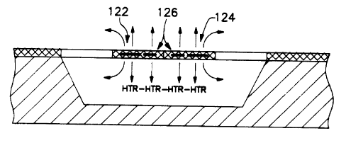
of the elements 122, 124 and 126 are used as heaters.
Figure 7b is an embodiment which is similar to the
embodiment of Figure 1 with thin film element 126 acting
as heater and elements 122 and 124 2~cting as sensors.
Tha embodiment of Figure ?c, represents the preferred
arrangement in which the element 122 acts as heater and
element 124 acts as sensor. The affective gap and thus
the thermal. isolation between heater and sensor is
desirably wider in the embodiment of Figure 7c.
Tha actual general geometric structure of the
embodiments of Figures 1-3, and 7a-7c is more clearly
illustrated in the scanning electron micrograph (~E~)
photo of Figure 8. The precision with which the cavity
and bridge ~rlements are defined and located in spaced
ra~leti~n, as Figure 8 depicts, is particularly
noteworthy. The SEF~I represents a magnification such
that the indicated length of 0.010~' appears as shown.
In tile implementation o! the invention
disclosed herein particular attention is directed to (1)
setting specific temperature marDcers in the sensor to
determine tlae time periods needed for achieving the
hl y Feb ':~ b"1 .. . ~.1
17 a
corresponding temperature chbnges, (2) using temperature
sensors which are physically separated from the heater
so that the direct influence of the heater and heat
conducted to the sensor other than via the fluid of
interest is reduced, and ~3) using a pulse which reaches
at least a momentary steady-state plateau to determine
k, which then is used with the transient measure to
determine cp.
Figure 6 graphically depicts a square wave
electrical energy pulse 130 to the heater as at 126
which results in quasi square wave heat pulses released
by the heater. These in turn, result in reactive curves
as at 131, 132 and 133 at the sensor which vary as
described below. The pulse applied to the heater, for
example, say have a height of about 4 volts with a pulse
width of 100 ms. Since the heater is closely coupled
through the fluid medium to the sensors, the family of
curves 131, 132 and 133 resembles the shape of the input
pulse 130. They show the heat response in the sensors
1Z2 and 12Ø Figure 11 represents an oscilloscope trace
showing temperature rise and fall versus tine for dry
air at atmospheric pressure. It uses a different scale
for ti~ae than do~s Figure 6, but illustrates the curve
form produced by the pulsed input. The curves generally
include beginning and ~ndimg transient portions flanking
a relatively ~t~ady-state central portion. The
relatively quick response of the sensor allows a
Z
2 0 ~-
relatively long steady~state to exist even with a pulse
of 100 ms. Of course, the curves are affected by
factors such as pressure and temperature as they
influence the effective thermal conductivity and
specific heat of the particular fluid of interest.
Heat flowing from the heater element or
elements to the sensor element or elements is conducted
both through the fluid and through the solid
semiconductor element support substrate or the like. Tt
is advantageous with respect to the measurement of k or
cp of the fluid of interest that the amount of heat
reaching the sensor through the solid connections be
minimized so that substantially all the measured
thermal effect is generated via the fluid of interest.
With respect to the transfer of heat to the
sensors) some background infonaation regarding the
propagation of heat or temperature waves is presented.
The speed of propagation, v, of a one dimensional wave
(if it features an exponential decay profile) is
constant and given by the expression:
~~a ~ (~T~b)O.~v (1)
where:
a is an exponential decay constant
b is the rise tim$ constant at a fixed
location and
DT is the thermal diff~asivity.
CA 02029292 2001-05-08
64159-1173
- 21
A complete list of nomenclature and subscripts
with units appears in Table 3, below. DT is related
to k and cp by the expression
D,t = k/ cp
DT, therefore, if known, may be a key to
obtaining cp. The rise time constant, b, was measured
to be about 4 cosec. For typical gases, DT ranges from
I
1.7 cm2/s for He to .054 cm2/s for C3H8. Metals
exhibit high values such as 1.7, 1.1 and .18 cm2/s
1o respectively for Ag, Cu and Fe. Insulators, however,
are even lower than the gases at .004 cm2/s for glass
and .0068 cm2 for Si3N4 which, as discussed above,
' is a good insulator. The propagation sped, v, in a
typical gas sample then is about (1/0.004)0'5 = 15
cm/s. This compares with (0.0068/0.004)0'5 = 1.3 cm/s
for Si3N4, assuming that the same rise time constant
of about 4 ms is applicable to both the one measured in
the Si3N4 and the actual one in the gas.
The effect is that the influence of the
2o temperature wave propagating from one thin film strip,
that is, the heater, to a second thin film strip, the
sensor, both being embedded in a membrane of Si3N4,
is faster for the gas than for the Si3N4. This also
supports the choice of a material such as Si3N4,
since it reduces the contribution of heat flow through
the solid media. This is beneficial to the accuracy of
the system.
c .f ~~'ts'~.:~7
f~ ~a ~~ w~ ~.J
_ 2Z
Typical microbridge embodiments are illustrated
by Figures 7a - 7c. They will now be explained in
greater d$tail.
CA 02029292 2001-05-08
64159-1173
23
TABLE 3 - NOMENCLATURE
Symbol Units
a Exponential Decay Constant cm
al-an Constant
A Area of Heat Transfer to Microbridge cm2
or to Gas
b Rise Time Constant at a Fixed Location 1/S
cp Specific Heat cal/ (cm3
C)
DT Thermal Diffusivity, DT = k/cP cm2/s
k Thermal Conductivity cal/ (sm
C )
L Length of Thermal Conductance Path cm
in Gas or Solid
P Pressure of Gas psia
Q Power of Heat Release Rate watts
Ro Resistance at Room Temperature ohms
t Time s
T Absolute Temperature C
U Bridge Output or Amplified Bridge V
Output
V Volume of Gas or Solid (Microbridge) cm3
v Speed of Propagation cm/s
why Power provided to, and dissipated by wa
sensor heater due to conduction
x Temperature coefficient of resistance C-1
CA 02029292 2001-05-08
64159-1173
23a
SUBSCRIPTS
c Conduction
S Microbridge or Solid
g Gas
o Room, Reference or Gas Temperature
without Microbridge Heating
h Heater or Hot
m Middle or Medium
,~,~6~'~;~.'1'3
r
i ~~d e: :e e~ !~
- 24 -
The configuration of figure 7a involves using
the same microresistance 122, 124, 126 for the heating
pulse and the sensing task. zn this embodiment of the
resistive heater-sensor element may be one leg of a
conventional resistive Wheatstone bridge in a control
circuit.
Figure 7b depicts an arrangement wherein the
center microresistance structure 12~ is used as a heater
flanked by two symmetrically located outer sensing
resistance elements 122 and 124. The elements 122 and
124 are separated from the heater 126 by a narrow gap.
Figure 7(c) shows an embodiment configuration
in which the left element of the bridge 122 is used as
the heating element and the right element 124 as the
sensor. This embodiment takes advantage of a rather
large central gap to achieve improv~ad thermal isolation
between the heater and the sensor.
Figurs ~ shows a modified control circuit which
uses the center microresistance 126 as heater, while the
sensing Mask is performed by the two resistors 122 and
124. The dual heater sensor configuration corresponds
to Figure 7b and the circuit is representative of
typical sensor/measurement circuit. Figure 9 includes a
timer 140 pr~viding square-wave electrical pulses to the
heater 12s. The heater c~upl.ea the heat pulse ~o the
sensors 122 and 124 in the bridge 142. The output of
CA 02029292 2001-05-08
64159-1173
- 25 -
the bridge is connected through an amplifier 143 to a
pair of comparators 144 and 145 which operate "start"
and "stop" inputs to a counter 146 which counts 10 mFiz
clock pulses. The counter counts measure the time
interval (t2 - ti) between temperatures T2 ~ T1
illustrated in Figure 6.
Figure 9a is similar to Figure 9, but more
detailed. The bridge configuration is the heater -
space-sensor configuration of Figure 7c. The sensor
resistance arm of the microbridge is set into a
Wheatstone bridge 150 at 124. Another proximate
resistive arm 122 is fed a voltage pulse from pulse
generator 151 to provide a heat pulse into the
microbridge element 126. The Wheatstone bridge 150 also
may contain a pulling balancing resistor 152 which can
be used in the manner of potentiometer 60 in Figure 5 to
initially zero the device. The microbridge resistor
sensor 124 in the Wheatstone bridge receives the heat
pulse from heater element 126 principally by thermal
conduction through the surrounding fluid. Some
conduction, of course, does occur through the solid
microbridge substrata and surroundings.
The circuitry of Figure 9a is conventional and
can readily be explained with reference to its
functional operation with regard to processing the
bridge output signal. The voltage output signals of the
CA 02029292 2001-05-08
6159-1173
- 26 -
bridge 150 are amplified by differential amplifiers 153
and 154 in a differential amplifier section. The
imbalance signal is further amplified by a high gain
amplifier at 155. The signal at 156 as is the case with
the signal at 143 in Figure 9 is in the form of a DC
voltage signal, U, the amplitude of which is solely
related to the thermal conductivity of the fluid of
interest as will be discussed above.
The remainder of the circuitry of Figure 9a
to includes a DC level clamping amplifier 157 and isolation
amplifier 158. The temperature level, time-related
switching and counting circuitry includes comparators
159 and 160,togethar with Nand gates 161 and 162 having
outputs which are connected to the counter timing device
(not shown) as in Figure 9. ey measuring the time
needed for the sensor temperature to rise or fall
between two or more known temperature values or markers
as represented by sensor resistance or bridge voltage
outputs a measure related to the specific heat per unit
volume, cp of the fluid of interest is obtained. The
timing device may be a conventional 10 l~iz pulse counter
or the like. Again, this is illustrated schematically
in Figure 6.
The output signal from the Wheatstone bridge,
U, represents the voltage imbalance caused by the
temperature change in microbridge sensor or sensors
CA 02029292 2001-05-08
641'59-1173
27
induced by the corresponding heater pulse output. Because the
magnitude of this imbalance is related directly to the amount
of energy absorbed by the sensor or sensors, the amplitude of
the signal is directly related to the thermal conductivity, k,
of the conducting media in a manner next explained.
"The power provided to the heater 126 (Fig.9) or
156 (Fig.9a) , 4Vh~, is another measure that is useful in the
computations to be described below. It is measured by the
voltage to ground at point 156 (Fig.9a)m Uh, knowing the value
of the heater resistance, Rh, as a function of temperature, from
determinations before the sensor was assembled: Why=Uhz/Rh.
Furthermore, if the heater control is set to a second
temperature, Tz, a second heater power measurement can be made,
Whiz, that reflects on the heat dissipation of the fluid as a
function of temperature, where the subscript 2 indicates the
second temperature"
Figure 6 shows that during much of the about 100ms
wide pulse period the temperature of the sensor reaches and
maintains a constant value. During this time, the influence of
the energy sink or source terms represented by specific heat
are zero, which means that only thermal conductivity governs
the value of the sensor temperature.
Figure 12 is a plot of temperature rise in the form
of bridge output, U, (Figure 9 or 9a) using the sensing
arrangement of Figure 7(b) versus time in milliseconds for
various gases at atmospheric pressure. Curves for methane, dry
air, ethane and a vacuum are presented. In this specific
embodiment there was a heater resistance of 800 ohms, a pulse
height of 2.5 volts, and a pulse width of 100 ms. Temperature
markers t, and tz are shown on the graph. These markers relate
to those of Figure 14 which shows a graphical presentation of
CA 02029292 2001-05-08
64159-1173
27a
heat up time versus pressure for several gases with a sensor-
heater such as that shown in Figure 7b and using the T2-T1,
marked in Figure 12.
- 28 -
The literature value of the thermal
conductivity of several gases has been plotted vs. the
aneasured sensor temperature expressed directly in terms
of the measured Wheatstone bridge imbalance patential,
U. This relationship has been derived empirically for a
microbridge of the type depicted in Figure 7(c) and is
plotted in Figure 13, using the least squares method in
a multiple regression analysis to achieve the best fit
curve. The relation can be linearized aver a modest
span sufficient for the purpose of the invention, other
combination configurations of heater/sensor embodiments
can likewise be calibrated using known gases or gases of
known k. Thus, using an off~the-shelf flow sensor of
the type 7(c) in the circuit ~(a), a 4.07 pulse of 100
ms duration was used.
This yielded an approximate linear relationship
between U and kg of the form
kg a a~U ~ a5 (3)
where
a~ _ -25.8807 arid a5 = 181:778 for the
above conditions.
The abave then achieves the calibration of the
seas~r for kg. The linear approximation holds over
enough of a span to provide accurate measurements.
~~~~'~~ JE:
-° 2g -
Similar relations may be derived under other measurement
conditions including additional pressure correction
terms.
Further details related to determining the
coefficients for the algorithms to compute cp are
described next. This determination rec,~uires that the
measuring system be calibrated first, which consists of
determining the coefficients al, a~, and a3, of
the algorithm to then computer cp.
Assuming a two-dimensional model for heat
transfer in the microbridge, see Figures 7a-7c, the
measured sensor temperature response may be described
with reference to the following processes (at zero gas
flow):
1) Heat release by the heater element film.
2) Temperature build up in the heater
ele~aent material (FeNi or Pt) and
surrounding support material (insulator
Si~N4), i:e. within the bridge
material.
3) Conduction towards the sensor via a) the
bridge material, and b) the fluid phase
surrounding the bridge.
4) Temperature build up in the sensor
material (as in heater material in item 2
above), and in the gas surrounding it by
CA 02029292 2001-05-08
6159-1173
- 30 -
the heat arriving via the above
processes.
5) Achieving a steady-state distribution of
' temperature.
6) The revenue process to steps 1-5 during
the start of the heater off-period.
' Further assuming, for the sake of simplicity,
that the specific heats of the involved gaseous and
solid materials do not depend on temperature, we can
l0 approximately describe the above processes by the
following expressions (see Table 3 above for symbol
explanation) using the same process numbering as above:
1) Q = V2/(Ro(1 + ~(Th-To)) for small
temperature rises.
2) The heater temperature results from balancing the
heat input and output rates: Th-To =
Q/(ksAs/Ls + kgAg/Lg) with Q in watts;
the temperature Th is established in a time that
is short compared to the time it takes to reach the
2o sensor if the sensor is not identical to the heater,
as in configurations 7(b) and 7(c).
3) In a truly one-dimensional cans most of 50~ of the
released power Q eventually arrives at the sensor,
since it only has two ways to go (+x and -x
directions). In a two- (or even three-) dimensional
case a major part of Q gets dissipated in the y and
- 31
z directions, so that only a fraction, Qc, is
conducted to the sensor, with a corresponding drop
of the original te~geratura, Th, down to an
inter~adiata temperature T~. The sensor than
experiences an energy rate arrival of
Qc = (T~-To) (ksAs/Ls + kqAq/Lq) (4)
4) ~ The sensor te~aperature rise rate is governed by the
specific heat of the gas surrounding the sensor and
the closely coupled material of the sensor itself so
that:
Qc = (dT/dt) cpsVs + (dT/dt)cpgVg (5)
The quantity measured and Blotted in Figures 14, 15
and 16, is the time (dt) needed to raise the sensor
temperature by an increment (dT) which is chosen by the
two or more sensor resistance value markers
corresponding to T1 and T~.
It is readily apparent from equation (5) that cpg
could ba datar~linead for an unknown gas if the various
quantities entering in Eqs. (4) and (5) were either
known or raaasura~le. It hays been found, however, that
even if only d~, d~, To, P and kg are conveniently
,z
~~~~~~~%
° 32
measurable, the other quantities may be determined by
calibration. This can be done according to an invention
as follows:
For calibration, gases of known composition
(preferably but not necessarily pure) and therefore of
known specific heat and thermal conductivity at the used
pressure and temperature (both also measured), are
brought in contact with the sensor. The effect of the
pulsed heat releases is recorded in terms of the lapsed
time, t2°t1, as has been described. After noting
results for various gases, pressures, heater
temperatures and/or heating/cooling periods, with pulses
of constant temperature, voltage, current or power, the
recorded time and condition data are entered into an
array of data ports which can be used for automatic or
computerized data processing or other number crunching
techniques.
The process can be illustrated with the help of
equations (4) and (5), by way of example, without
~xcluding other, similar approaches likely to occur to
one skilled in numerical analysis. With this in mind,
the following ports receive data or input fox various
gases, pxe~sures (and temperatures):
Poxts: Y X~. %2
Inputs: cpgP/Po (tytZ)kg t2-tl
n
!_j ~ ~J
- 33 -
Known and available multiple linear regression analysis
(MLRA, see Figure 10) program can determine the linear
coefficients al, a2, and a3 (e. g., by matrix
inversion), which, together with the above input data,
forms the calibrated expression derived from equations
(4) and (5) to compute specific heat, cp:
cpg P/Po ~ al(t2-tl)kg + a2(t2-tl) -a3 (6)
The determined (calibration)coefficients, of
course, represent the lumped factors of several sensor
groperties or conditions from equations (6) and (7):
a la ( Tm-To ) ( fig/ Lg ) / ('~gdT )
a2 = (Tm Tn) (~g/Lg)/(Vgdz')k~I
a3 g cpsVs/Vg
In order to minimize differences in Tm at the
sensor location, the most advantageous operation from
among constant temperature, voltage, current or power is
chosen. The above method is demonstrated on the basis
of 1) constant voltage pulses, which result in quasi
square wave heat pulses released by the heater, and 2)
changes in gas type (CH4, CzH~, air and 0~) and
pressure; the chosen configuration was 7(b).
a. c F~, c~ .;~
- ~ ~~ ~ ~._, F.~Y r.:J
3 4 .~
Figure 14 shows the result of shoring and
plotting the dt = t2-tl and pressure data for eaeh
of the gases used, for which the cp and k values can
be obtained from the open literature. This relation is
linearized by applying the least squares method in a
multiple linear regression analysis to achieve the best
fit line. After entering these data into the above
ports Y, X1 and X2, the regression analysis program
performed. The obtained result was, far a configuration
as in Figure 7(b):
al ~ -16509, a2 = 3.5184 and a3 = .005392 ('~a)
Proof that the above calibration coefficients
are valid is provided by Figure 15, far example, in
which these coefficients have been used to generate the
shown lines for CH4, C2H6, air and 02. As
shown, the lines indeed connect and agree with all
experimental points. Additional lines have been plotted
with the cp and k data of the literature for other
gases as well.
The final step in using this calibration method
involves known means to store, write or burn in the
obtained, tailored values of al, a2 and a3 far the
individual microbridc~e, which may be a Honeywell
~s"a x' i; ~1
~ ~:~,~.~~
a ~ .f.,) a s 3 -L~ G~.3
_ g
MICRO-SWITCki Model No. AWM-2100V, into the memory linked
to it. The microsensor is then ready for use to measure
the specific heat of unknown gases, provided that P and
k be known at the time of measurement.
Figure 10 depicts a schematic block diagram of
a device for measuring cp and k. The system includes
the signal processing circuitry indicated by 170, a
multiple linear regression analysis (MxaRA) unit 171 for
deriving the known equation constants for the particular
microbridge configuration and circuitry used, i.e., al
- an, a data bank 172 for storing calibration cp and
k data and an output interface unit 173.
With respect to the embodiment of Figure l0,
prior to use, field recalibration may be accomplished
simply by entering the P, cp and k values of the
test gas into the data bank. If h caz~nat be measured
independently of the sensor already in the subject
system its err~rs can ba incarpo~ated as a correction in
the cp mnd k recalibration. The measured values of U
and dt are then used as in the measurement made to
detarnina sensor values of k and c~. If they disagree
from the entered values the cr~nstants a3 and a~ may
be modified to fit the entered or book values.
This approach may be a practical one for field
usa, but it should be checked by using ~ second test
- 36
gas. If that agrees, the recalibration may be
completed. If not, a complete calibration of all
al-a5 coefficients should be made.
Tt should be mentioned that in all of the above
discussion the influence of temperature was not
mentioned for the sake of simplicity. It is well known,
however, that temperature does influence both cp and k
but can be addressed, if necessary, in one of the
following ways:
1) Controlled, (expensive and energy
consuming) or
2) Compensated by speeial
temperature-sensitive elements in the
analog part of the circuit, ar
3) Entered into the sensor algorithm as an
additional parameter, which is sensed,
e.g., by monitoring one of the many
available temperature dependent resistors
on the sensor. This is the preferred
approach for sensing systems ree~uiring
maximum accuracy
With respect to use of the instrument of Figure
10, the U and dt ~ t2-t1 (and P) signals obtained
for an unknown gas are processed as follows in this
mode:
__
37
Computation of k from expression (3)
using the coefficients a4 and a~
which have b~sen stored in (or burned
into) the sensor's memo, after
calibration, and
a) Computation of cp from expression (6).
It should also be noted that a pressure
signal is also needed as a basic
ingredient since cp is used here in
relation to a voluxae of gas as opposed to
k which is largely pressure independent
if the sensor is used at or above
atmospheric pressure, at which the gas
mean free path is small compared to the
characteristic dimensions of the involved
sensor.
The graphical presentation of Figure 16 depicts
heating time in milliseconds versus pressure and gas
type and specifically showing eux°~r~s fob methane,
ethane, air and oxygen. The sensing configuration of
Figure 7(c) was used. In this example, the pulse height
was 1.75 volts with a pulse width of l0~ ms. and the
heater and sensor resistance each beang about 2opa
ohms. Figure l7 depicts ~ cooling curve fox the same
configuration as Figure l6. conditions were the same
except that the pulse height way ~,.0 volts,
___ r c~ sa
a..a ! ,,,
.~ 3~
Of course, the output o~ the device can be in
any desired fox~n including analog or digital signals,
printed records, etc., agter the value is obtained.