Note: Descriptions are shown in the official language in which they were submitted.
20Z9609
~I~LD OF rNVENTION
This invention relates to porting system for hydraulic devices and in
particular relates to gerotor oi; pumps having an intake port and exhaust port with a
cross-sectional area in the direction of rotation of said gears which varies in relation
to the rate of change of the pockets between the gear teeth.
BACKGROUND TO THE rNVENTION
Positive displacement porting systems on gerotor oil pumps generally
consist of an intake port, an exhaust port and an internal relief system which directs
relief oil from the exhaust port back into the intake port.
There have been various designs heretofore in oil pumps including
gerotors oil pumps in order to efficiently pump fluids.
For example, United States Patent No. 3,289,599 relates to a gear pump.
More particularly, United States Patent No. 3,995,978 teaches inlet ports
which are generally arcuate or kidney shaped which extend circumferentially for
approximately the line of eccentricity on one side of the hydraulic device to
approximately the line of eccentricity on the opposite side of the hydraulic device.
Moreover~ United States Patent No. 4,492,539 illustrates a gerotor pump
having displacement control means for changing the volume of fluid delivered.
Yet another arrangement illustrated in United States Patent No. 4,767,296
which shows that when the in rotor rotates, a sealed space has its volume reduced to -
. . .
have internal oil pressure accumulated.
Finally, United States Patent No. 4,758,130 discloses various arrangementof ports or galleries of a pump.
These an other arrangements of hydraulic pumps and in particular porting
systems have generally limited utility.
It is an object of this invention to provide a more efficient porting system
for hydraulic devices and in particular to provide a more efficient porting system for
gerotor oil pumps.
It is an aspect of this invention to provide a porting system for a hydraulic
device cornprising; a housing having a chamber cornmunicating with an intake port and
20 an exhaust port; a pair of rotary gears disposed internally of said chamber adjacent said
ports and defining expanding and contracting pockets as said gears rotate over said
intake port and said exhaust port respectively; wherein said ports have a cross-seclionai
area in the direction of rotation which varies with the angular displacement of said gears
whereby the incremental rate of change of said cross-sectional area is based on said rate
of change of said expanding and contracting pockets.
~q
It is another aspect of this invention to provide a hydraulic pump for pump
fluids comprising; a housing having an intake passage for introducing said fluid, exhaust
passage for exhausting said fluid and an end face, said intake and exhaust passage
defining at said end face and intake port for receiving said fluid and said exhaust port
for exhausting said fluid; an internally tooth rotor having an axis of rotation and an
externally tooth rotor eccentrically disposed within said internally tooth rotor and having
an axis of rotation, said axis of rotation being spaced apart; a shaft operatively connected
to one of said rotors; said teeth of said rotors inter engageable to define a plurality of
10 expanding and contracting volumes as said rotors rotate about said intake port and said
exhaust port respectively; said ports having a cross-sectional area in said axial direction
which changes with the angular displacement of said rotor, whereby the increment rate
of change of the cross-sectional area along the entire port is inversely proportional to the
incremental rate of change of expanding and contracting volumes respectively.
It is a further aspect of this invention to provide a method of maintaining
a substantially constant acceleration of fluid within the entire area of an intake port and
an exhaust port defined by an intake passage and an exhaust passage communicating with
a chamber having rotary gears defining expanding and contracting pockets as said gears
20 rotate within said chamber by utilizing ports having a cross-sectional area in the direction
perpendicular to said rotation of said gears which with the angular displacement of the
rotary gear whereby the incremental rate of change of the cross-sectional area is
inversely proportional to the rate of change of said expanding and contracting pockets.
.~
2029~jQ9
It is yet another aspect of this invention to provide a method of
producing an intake port and exhaust port in a hydraulic device having a fluid chamber
with rotary gears disposed within said fluid chamber adjacent said port so as to define
expanding and contracting pockets as said rotary gears rotate about an access within
said fluid chamber, said method comprising the steps of:
(a) determining the radial and axial size of said ports;
(b) determining the initial and final depth or said ports;
(c) determining the rate of change of said pockets as said rotary gears rotate
about said ports;
(d) manufacture the depth of said ports wherein the cross-sectional area of
said passages varies in relation to the rate of change of said expanding
and contracting pockets.
DESCRIPrION OF THE DRAW~GS
These and other objects and features of the invention shall now be
described in relation to the following drawings.
Figure 1 illustrates a top view of said ports with the relief valve.
Figure 2 illustrates a cross-sectional view of said port depth along the lines
2-2 of figure 1.
Figure 3 illustrates a top view of said ports with rotors.
Figure 4 illustrates a side elevational view of said ports along the lines 4-4
10 of Figure 3.
DESCRIPTION OF THE INVENTION
Like parts shall be given like numbers throughout the figures.
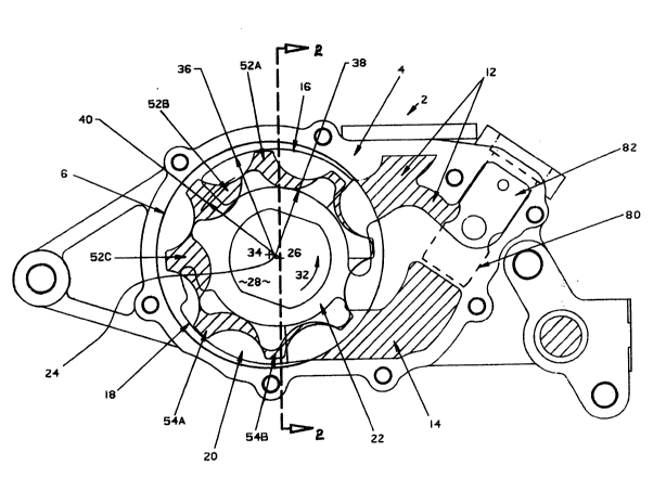
Figure 1 generally illustrates the hydraulic pump or gerotor pump 2 having
a housing 4 which includes a chamber 6 which is illustrated in figures 1 and 2 comprises
of a recess or hole having a cylindrical cross-section. The chamber 6 also includes a flat
20 end face 8 as best illustrated in figure 2.
It should be noted that the housing 2 as illustrated herein is adapled to be
either bolted to an engine block along surface 10 by means of bolts or the like (not
20296~3
shown) so as to produce a sealed unit in a manner well known to those persons skilled
in the art.
The hydraulic device 2 also includes intake passage 12 adapted to receive
fluids such as oil as well as exhaust passage 14 adapted to the exhaust fluids such as
oil.
The intake and exhaust passages 12 and 14 communicate with chamber
6 and in particular communicate with end face 8 through intake ports 16 and exhaust
port 18.
Chamber 6 is adapted to receive first or inner tooth rotor gear 20 and
second or externally tooth rotor gear 22 eccentrically disposed within the inner tooth
rotor gear 20. Inner tooth rotor gear 20 is adapted for rotation within chamber 6
about a first axis 24 while a second or externally tooth rotor gear 22 is adapted to
rotate about a second axis 26 which is spaced apart from first axis 24 as best illustrated
in figure 1.
A shaft 28 is operably connected to inner rotor 22 as illustrated in figure
1. However, the shaft 28 may be operably connected to either the inner tooth rotor
20 or externally tooth rotor 22.
The arrows 30 illustrated in figure 3 show the direction of oil flow.
Moreover, arrow 32 shows the direction of rotation of rotors 20 and 22.
Axis 26 also defines the origin of inner rotor 22. Point 34 in figure 1 shows the half-way
point of the off-set or half the distance between axis 24 and 26. Numeral 36 defines the
outer port radius, while 38 defines the inner port radius. Moreover, 40 illustrates the
major radius of the inner rotor 22. Inner tooth rotary gear 20 and externally tooth rotor
gear 22 define a series of expanding volumes or pockets 52 (a), (b), and (c), as well as
a series of contracting volumes or pockets 54 (a) and (b) as best illustrated in figure 1.
10 The expandlng pockets 52 (a), (b) and (c) as disposed adjacent the intake port 16 while
the contracting pockets 54 (a) and (b) are disposed adjacent the exhaust port 18. The
expanding pockets 52 have the effect of drawing fluid from the intake passage 12 and
intake port 16 which will then be transported by the rotating gears 20 and 22 in a rotary
direction of arrow 32 to be exhausted through exhaust passage 14 by means of the
contracting pockets 54 (a) and (b) which force the fluid through the exhaust port 18 and
out through exhaust passageway 14.
As best illustrated in figure 2 the gears 20 and 22 have the same depth or
dimension in the axial direction of axis 26 or 34.
In accordance with the invention as described herein, the axial depth 60
of intake port 16 as well as the axial depth ~2 ot the exhaust port 18 are manufactured
in a manner such that the port depth 60 and 62 of intake port 16 and exhaust port 18
have a cross-sectional area in the direction of rotation of the gears 20 and 22 in
,..j:
20~9fi~9
relation to the rate of change of the gears 20 and 22 in relation to the rate of change
of the expanding and contracting volumes or pockets 52 and 54. In particular, the
cross-sectional area of intake port 16 and exhaust port 18 varies in relation to the rate
of change of the expanding and contracting pockets 52 and 54 in a direction
perpendicular to the direction of rotation.
Figure 4 best illustrates the axial depth 60 of intake port 16 as well as
the axial depth 62 of exhaust port 18 along the direction of rotation of the rotors 20
and 22 along lines B-B as shown in figure 3. In particular, line B-B is taken along an
arc which approximately represents the middle of the ports 16 and 18.
In other words, as the expanding pocket 52 (a) expands to the size of
expanding pocket 52 (b), the depth of the intake port DEl becomes smaller as
illustrated by DE2. In other words, the cross-sectional area of the intake port 16 which
is illustrated in figures 1 and 4 are defined by surface 10, outer port radius 36 and
inner port radius 38 as well as the depth 60. Therefore, as the volume of expanding
pockets 52 expands, the cross-sectional area of intake port in the direction of rotation
diminishes. Since the axial depth of rotors 20 and 22 are constant, the cross-sectional
area of intake port 16 will vary inversely with the area of the expanding pockets 52.
The exhaust port 18 is constructed in a similar fashion. It should be noted from figure
4 that the depth of intake port 16 to the right of DE, is relatively constant and
diminishes in the direction of rotation 18 from DE, onwards, that is just past the
introduction of fluid from the intake passage 12.
9 20296Q9
The depth of the port 16 and 18 are manufactured as an interpellated
curve where the cross-sectional area of the port 16 and 18 respectively is in relation
to the gear pocket rate of change.
Moreover, the vector flow angle which is shown as number 70 in figure
4 which comprises of the vector addition of the horizontal and vertical component of
the velocity of the oil is constantly decreased from the beginning of the port to the end
of the port. In this way, it is believed that the acceleration of the fluid or intake oil
is constant within the entire port area and the final velocity of the oil flow at the end
of the intake port is nearly equal to the rotor pitch line velocity.
Accordingly, the system as described herein allows the oil to flow
smoothly into the separating gear sets with substantially no unnecessary acceleration or
deceleration of oil in the port area. Since constant acceleration ports are generally
shallower than standard gerotor ports, such systems can be prone to some high speed
cavitation due to shearing of the oil between the rotor face and the bottom of the port.
Accordingly, a relief conduit 80 is utilized which is adapted to receive a relief valve
as shown in figure 1 in order to minimize the cavitation potential. Since the constant
acceleration ports will allow for smooth intake and exhaust pressure pulses, the relief
oil can be directed into the intake port in such a way that the system as shown herein
becomes pulse tuned. The velocity profile of the relief oil is analyzed and the relief
conduits are shaped and sized to inject the oil into the maximum rate of change area
Z02~fi~9
of the intake port at the correct velocity and time. The internal energy in the relief
oil is used to assist in the acceleration of the intake oil reducing the intake pressure
drop and minimizing the cavitation potential. The injected oil also maximises the
mechanical efficiency of the pump by using energy which will otherwise be wasted.
Details concerning the relief valve are subject matter of a patent application filed by
applicant on even date of this application.
Accordingly, the invention as described herein relates to pulse tuned
optimized porting whereby the incremental rate of change of the cross-sectional area
of the intake port is equal to the rate of change of the pocket of the area between the
rotor teeth as they open up. The rate of change of the pocket area and hence the
depth of the port varies with the angle of rotation of the rotors with the maximum
near the centre of the port where the rate of change of the opening of the pocket is
the greatest, while at both ends of the port, the rate of change of the depth is close
to zero.
When designing or constructing the ports as described herein, the initial
and final port depth is predetermined by the user. The incremental ratio of the rate
of change of the rotor pockets will be applied to the total difference of the initial and
final port depth. The actual port depth at a particular angle of rotor rotation will be
calculated by the combination of the differentially based constant velocity (resulting in
the port cross section) and the constant accelerating slope of the initial and final port
depth. The final profile of the port will be manufactured into the housing. The
2V29~
11
exhaust port can be obtained by mirroring the intake port about the off-set of the
housing. Through the use of specialized port shapes and flow velocity optimization or
port vectorization, the system can be integrated and optimized to minimize cavitation
and maximize pump efficiency.
Although the preferred embodiment as well as the operation and use
have been specifically described in relation to the drawings, it should be understood
that variations in the preferred embodiment could be achieved by a person skilled in
the trade without departing from the spirit of the invention. Accordingly, the invention
should not be understood as to be limited to the exact form revealed by the drawings.