Note: Descriptions are shown in the official language in which they were submitted.
203~017
The present invention relates to
manholes and more particularly, to novel liner
sections and cooperating novel gasXet means and
assembly means for rendering the liner section
waterproof to protect manhole assemblies against
corrosion.
Manhole assemblies have been found to
typically experience significant interior
corrosion and deterioration even in cases where
high acidic effluents that are Xnown to be
harmful to sewers and sewer treatment are
prohibited from entering the sewers before first
being dissipated or neutralized. Nevertheless,
hydrogen sulfide which is inherent in sewage, is
developed due to the presence of sulfur
compounds, e.g. sulfate, sulfite, or other
inorganic or organic sulfur. The
above-mentioned group of compounds are reduced
to sulfide by sulfate-reducing bacteria normally
found in the effluent. The generation of
hydrogen sulfide is accelerated in the presence
of high temperature and low flow rates. The
useful life of concrete is determined by
_ -2- 203001~
dividing the available effective thickness of
the concrete by the corrosion rate. The
corrosion rate can be calculated when all
factors are known. The effective thickness of
the concrete is the amount covering the steel
reinforcement typically embedded within the
manhole assembly.
Coatings have been applied to manhole
interiors but have been found to have a poor
track record. For example, although coal, tar,
or epoxy provides effective protection against
hydrogen sulfide, such coatings have provided
poor field performance due to application
difficulties.
As a result, linings of plastic
material, e.g. polyvinyl chloride (PVC),
provide the best performance for interior
corrosion protection against hydrogen sulfide.
Such plastic linings are further compatible with
plas~ic pipe now being used extensively in
sanitary systems. To date, however, it is
extremely difficult to fabricate interior
linings and integrate such interior linings into
vertical structures and particularly manhole
assemblies. Flexible type linings are presently
used in pipes covering the upper 270 of the
pipe interior. This portion is attacked by the
H2S generated from sewage. This flexible
material is not easily used on manholes which
require 360 protection for the manhole
interior.
203~01~
U. S. Patent No. 4,751,799, issued
June 21, 1988 and assigned to the assignee of
the present invention, discloses liners formed
of a rigid or semi-rigid material, which liners
are fabricated in sections. For example, the
liners are fabricated as four separate
quadrants. Each quadrant comprises a curved
molded member which may, for example, be
thermo-formed. Each molded member is provided
with a plurality of projections each having a
ducktail cross-section for securing the liner
into the concrete structure. The liner sections
are joined together and caulked along their
engaging edges. The projections of ducktail
cross-section extend outwardly from the convex
surfaces of the mold members which are arranged
with an interior mold assembly and are either
joined against the surface of an interior mold
member by standard plastic banding or are
alternatively joined together end-to-end by
individual holding members. These assemblies
have been found to lack suitable structural
strength and present additional problems in
their handling and assembly. In addition, the
caulking material has been found to provide
unsatisfactory waterproof seams within the
manhole assembly structure.
2030~
It is, therefore, one object of the
present inventior. to provide precast concrete
vertical place structures or manhole assemblies
having novel liner assemblies impervious to
toxic materials for protecting the concrete.
Still another object of the present
invention is to provide a novel liner assembly
for lining and protecting annular concrete
structures and the liXe from corrosion, said
liner assembly being formed of liner sections
having integral flanges joined to one another by
suitable fastening means, resilient gasket means
being provided between the joined flanges and
further including at least one flange serving as
a means for clipping the gasket to one of said
liner section flanges preparatory to assembly to
facilitate the assembly operation.
Still another object of the present
invention is to provide novel liner sections and
gasket means, the liner sections being joined to
one another with the gasket means arranged
therebetween and including novel fastening means
for assuring adequate securement of liner
sections to one another and providing a good
liquid-tight seal between the joined sections.
20300~7
s
The present invention is characterized
by comprising a novel manhole liner assembly
which includes curved liner-sections which are
assembled toget'ner to for~ an interior liner
assembly.
The interior liner assembly for the
present invention is utilized for precast
concrete wastewater structures which combines
tne immense structural strength and integrity of
reinforced concrete with the chemical resistant
advantages of the liners, which are preferably
formed of polyvinyl chloride (PVC).
The liner is preferably thermo-formed
from a semi-rigid thermoplastic sheet to the
required contour of the manhole structure. A
ribbed design is utilized to integrally cast the
liner to the concrete wall during the
manufacture of the precast component.
Elimination of ducktail-shaped projections, in
addition to eliminating unnecessary
manufacturing steps also provides a permanent
mechanical bond to the concrete and, once the
concrete components are assembled on the job
site, provides a continuous and impermeable
lining for shielding the concrete against
deterioration by corrosive matter. The liner
also allows pipe entry openings to be lined and
sealed to further safeguard against corrosion.
-6- 203001~
Each of the liner sections are joined
about'their sides by means of a novel rubber
~s~et comprising an elonga~ed strip having a
predetermined cross-section and provided with an
integral flange to permit the gasket to be
"clipped on" to a flange of one of the molded
liner sections to automatically position the
gasket preparatory to assembly for greatly
simplifying the assembly operation.
As an alternative embodiment, the
gas'~et may be provided with a pair of such
flanges for coupling adjacent liner sections to
still further simplify the assembly.
The flanges are then mechanically
joined together either by self-tapping screws or
staples. An elongated strip of expanded metal
or plastic preferably in an angle shape (i.e.
L-shaped cross-section) may be utilized to
provide sufficient torque for insertion and
securement of the fastening means.
The apparatus of the present invention
provides distinct advantages over traditional
coatings and other protective measures presently
available for protecting concrete from corrosion
and sanitary sewer structures. The basic
properties of PVC in regard to being chemically
inert and having a superior strength to weight
ratio, creates a tough, corrosion resistant
surface giving the concrete structure surface
life compatible with PVC and PVC-lined pipe.
The assembly of the present invention provides a
long service life even under severe conditions,
providing resistance to ~2S, acids, alkalis, and
salts which attack sewer systems.
2030~7
--7--
In addition thereto, tne liner
sections are a smooth white which is highly
light reflective and environmentally pleasing
and further prevent fungus or bacteria from
permanently clinging to the liner allowing the
walls to be easily cleaned and maintained.
The novel resilient gasXet provides an
excellent watertight seal between adjacent
sections which maintains its integrity even
after long continuous use and which further
serves to greatly facilitate assembly of the
liner sections preparatory to casting. The
gasket flanges serving as "clips" also serve to
enhance the securement of the liner assembly to
the manhole member being cast integral with said
liner assembly.
Manhole assemblies including the
manhole base, riser and top sections may be
fabricated utilizing the liner sections
described hereinabove.
The liner assembly forms an integral
part of each cast member. The manhole sections
are assembled one upon the other. The liner
sections are each provided with flanges at each
of the mating surfaces of the adjoining manhole
sections. Suitable sealing means is provided
for assuring the provision of an excellent
liquid-tight seal. The liner protects the
manhole assembly from corrosion and is retained
in place within the cast members due to the
gaskets and ribs, assuring a rugged, serviceable
liner for protecting the concrete manhole
sections against corrosion.
_ 2030017
In the accompanying drawings:
Fig. 1 shows a sectional view of a
manhole assembly embodying the principles of the
present invention;
Fig. 2 shows a perspective view of
manhole section containing the liner sections of
the present invention and cast into the section;
Fig. 2a shows a sectional view of a
portion of the manhole assembly of Fig. 2:
Fig. 2b shows an exploded top view of
a typical rubber joint of the manhole assembly
shown in Fig. 2;
Fig. 2c shows a view of a
cross-section of another preferred embodiment
for the rubber gasket;
Fig. 2d shows a strip of expanded
metal for use in the fastening assembly of Fig.
2b, for example;
Fig. 2e shows an enlarged
cross-section of the gasket of Fig. 2b;
Fig. 2f is a perspective view of
another strip which may be substituted for the
strip shown in Fig. 2e;
Fig. 2g is an end view of the strip of
Fig. 2f;
Figs. 3a and 3b show perspective front
and rear views of a typical liner section;
Figs. 4a and 4b show sectional views
of an assembly for casting a manhole section
employing the liner assembly of the present
invention; and
Figs. 4c and 4d show sectional views
of adjacent manhole sections which views are
useful in explaining the liquid-tight joint
formed between sections.
_ 2~3~17
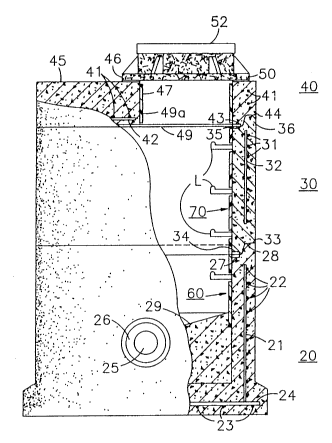
Fig. 1 shows a manhole assembly 10
comprised of manhole base 20, riser section 30
and top section 40. The base, riser and top
sections each have a cylindrical shape although
the top section 40 is shorter than sections 20
and 30 and provides a top opening for receiving
the cast iron frame and sewer lid cover shown
respectively at 50 and 52 in Fig. 1.
Base member 20 is formed of concrete
and has a steel reinforcing framework comprised
of a gridwork of vertically (straight) and
horizontally (annular) aligned rods 21 and 22,
respectively. A similar grid framework of
perpendicularly arranged (straight) rods 23 and
24 are provided in the floor of base member 20,
as is conventional.
Base member 20 is provided with at
least first and second openings, one of which is
shown at 25, each such opening being adapted to
receive one end of a pipe section. A resilient
rubber-like seal 26 is arranged within opening
25 and is preferably cast therein, but can be
hydraulically placed after the opening is either
cast or cored to provide a watertight seal
between the pipe section (not shown) and the
manhole opening 26.
-10- 203001 ~
The top edge of base member 20 is
provided with an interior shoulder 27 having an
outer projection 28 surrounding shoulder 27.
Cylindrical-shaped riser section 30
has a similar reinforcement structure comprised
of horizontally aligned (straight) and
vertically (annular) steel rods 31 and 32. The
bottom edge of the riser section has an outer
shoulder 33 which rests upon the top surface of
projection 28 and has an interior projection 34
surrounded by shoulder 33 and resting upon
shoulder 27, as shown. The top end of riser
section 30 is provided with an inner shoulder 35
and a surrounding outer projection 36 similar to
the shoulder 27 and projection 28 of base member
20. Top section 40 is reinforced by
horizontally aligned (annular) reinforcement
rods 41 and a reinforced steel plate 42, when
required. Top section 40 has a bottom edge
having an outer shoulder 44 resting upon
projection 36 and an inner projection 43 resting
upon shoulder 35. The cast iron cover support
frame 50 rests upon the top surface 45 of top
section 40 and is aligned with opening 46. A
water lock entry sleeve 47 may be provided
within opening 46. A cylindrical-shaped
protective liner 49 has a portion 49a extending
into a lower portion of opening 46 to provide
corrosion protection.
-11- 203~017
The sections 20 and 30 are provided
with corrosion protecting liner assemblies 60
and 70 each of which lines the entire interior
surface of the associated manhole section and
thereby protects the surface from corrosion.
Each liner assembly is provided with outwardly
directed horizontally aligned flanges 102, 103
at the upper and lower ends thereof (Figs. 2,
2a, 3a, 3b), which flanges engage flanges of the
adjacent liner assembly (Figs. 4a, 4b) in a
manner to be described in greater detail
hereinbelow. A suitable sealant is provided
between the adjacent flanges described
hereinabove to assure a watertight corrosion
resistant seal in the region of mating flanges.
Figs. 4a and 4b show the manner in which the
caulking material, to be more fully described
hereinafter, is squeezed out throughout the
mating surfaces to provide the desired
watertight seal.
Figs. 3a and 3b show a typical liner
section 100 in greater detail. The liner
assembly provided within each manhole section is
formed in sections as shown in Figs. 3a and 3b.
In one preferred embodiment, the liner assembly,
is formed in four separate 90 quadrants. This
90 quadrant section may be changed relative to
the manhole diameter for ease in the
fabricating, handling and shipping. Also, a
greater or lesser number of sections may be
provided while maintaining the advantageous
features of the present invention.
_ -12- 2030017
Quadrant 100 has a curved major
portion 101 with integral flanges 102 and 103
provided respectively at the top and bottom ends
thereof. In addition thereto, integral flanges
104 and 105 are arranged along the sides
thereof. The ends of the flanges 104 and 105
are joined to the ends of flanges 103 and 102
with the vertices preferably being somewhat
rounded. Flanges 104 and 105 are designed to
receive a gasket therebetween as will be more
fully described. Flanges 102 and 103 are
designed to receive the caulking material
arranged between these flanges and the adjacent
flanges of the upper (or lower) liner section
(Figs. 4a, 4b).
The liner section is further provided
with a plurality of integral curved ribs 106
arranged in spaced substantially parallel
fashion and extending outwardly from the convex
surface 107 of the liner section. The concave
surface lOla is provided with slight recesses
which are formed as a result of the formation of
the ribs 106, said ribs and recesses, as well as
the curved portion and flanges of each liner
section preferably being formed in a
thermo-forming operation, although a molding or
extrusion operation may be employed, if desired.
The four liner sections, in the case
of the preferred embodiment of the present
invention, are joined together preparatory to
casting a manhole section. For example, Fig. 2b
shows the right-hand end of a liner section 100'
~ -13- 203~017
ard the left-hand end of a lir.er section 100''
arranged pre~aratory to being asse~bled to one
another. Liner section 100' is arranged so that
its flange 104' lies a close spaced distance
from the flange 103'' of the liner section
100 ' ' .
An elongated continuous gasket 110
(see also Fig. 2e) extending at least the height
of the liner sections 100', 100'' is initially
mounted upon flange 104'.
The elongated gasket 110 has a
cross-section, as shown in Fig. 2e. The gasket
is preferably formed of a rubber or rubber-like
material e.g. EPDM.
The gasXet has two substantially
parallel major surfaces llOa, llOb. One side of
gasket 110 has a tapered portion defined by
tapered surfaces llOc and llOd which merge at a
tip llOe at the free end thereof. The surfaces
llOc and llOd taper away from tip llOe and each
terminate in a vertex llOf, llOg the sidewalls
llOh, llOi tapering rearwardly from vertices
llOf, llOg to merge with surfaces llOa, llOb.
The opposite end of the gasket cross-section is
similar to that of the first described end and
has tapered surfaces llOj, llOk which merge to
form tip 1101. Surface llOk extends rearwardly
to vertex llOm. Surface llOj extends outwardly
and merges with flange llOn which extends
parallel to surface llOa, forming slot llOp.
Vertex llOm tapers along sidewall llOq and
merges with surface llOb. The gasket is mounted
-14- ~0~05~7
to liner section 100' by insertion of flange
104' into slot 110p thus freeing the operator to
bring liner section 100'' against the opposing
surface of gasket 110. When the liner sections
are brought together in this manner, suitable
fastening means such as, for example,
self-tapping screw 112 is inserted through
flange 103'' through gasket 110 and through
flange 104'. A suitable number of fasteners are
arranged at spaced intervals along the
liquid-tight joint formed by flanges 104',
103'', gasket 110 and fasteners 112. Openings
110r, 110s permit the gasket to yield more so in
the regions of these openings to allow the
tapered portions 110f, 110g and 110m to compress
when pressed between the flanges to provide a
watertight seal along the entire sides of the
gasket and not merely the tapered portions.
In order to provide suitable fastening
torque for the self-tapping screws, an elongated
metallic strip 114, or plastic angle shape 114',
is positioned against the left-hand surface of
flange 104' as shown in Fig. 2c. Fig. 2f shows
a plan view of the expanded metal strip or
plastic angle shape 114 which, due to its unique
structure is easily tapped by the self-tapping
screw 112. A plurality of self-tapping screws
arranged at spaced intervals along the flanges
intimately secure the flanges to one another.
The tightening of the self-tapping screws cause
the rubber gasket to be compressed, and
especially the vertices 100m, 100f and 100g, the
compression being sufficient to provide an
excellent watertight seal between the joined
flanges.
-15- 2030G~7
Although not shown her~in for purposes
of simplicity, all four quadrants of the liner
sections are joined in a similar fashion,
resulting in an annular-shaped assembled liner
structure.
The fully assembled liner structure is
arranged within a conventional mold assembly of
the type shown, for example, in Figs. 4a and
4b. The molding technique shows the manner of
casting a manhole base in an "upside-down"
fashion and employing an inner mold member 140
and an outer mold member 150 resting on the base
mold member 141. Only a portion of the mold
assembly has been shown herein for purposes of
simplicity.
The fully assembled liner structure is
arranged against the convex surface of the inner
mold 140 as shown, for example, by liner section
100. Inner mold portion 140a defines the invert
provided within the cast manhole base.
The liner sections are retained
against the inner mold member 140 by the
fastening assembly shown, for example, in Fig.
2b and having the gaskets 110 compressed between
the flanges joined by each fastening assembly.
A steel reinforcing framework made up
of steel rods 21, 22, 23 and 24 are arranged in
grid-like fashion (note also Fig. 1) and are
inserted within the mold. Thereafter, the cast
material, preferably concrete, is poured into
the hollow region R of the mold assembly and is
allowed to set.
-16- 2 030 0 ~7
-
Once the cast material is set, the
entire assembly is inverted, whereupon the cast
member is now "right-side-up". The mold members
are then lifted away from the cast member. Fig.
2 shows a sectional view of a cast riser section
30 shown also in Fig. 1.
The ribs 106 as shown in Figs. 2a and
3b are embedded in the concrete and serve to add
structural strength to the resulting cast
member, the ribs and concrete cooperating with
one another to enhance the structural strength
of the resulting manhole section. The base,
riser and top sections are all formed in a
substantially similar manner using appropriate
mold assemblies. The riser and top sections can
be cast in either the right-side up or
upside-down fashion.
The manhole sections which receive
ladder members receive a plastic insert 143
prior to casting and thereby form openings
within the cast member for receiving the free
ends of the substantially U-shaped ladder
members L shown in Fig. 1. These plastic
inserts are described in detail in U. S. Patent
No. 3,974,615 assigned to A-LOK Products, Inc.
After the cast member is set and removed from
the mold assembly, the ladder members L (Fig. 1)
are pressed into the aforementioned inserts to
form a press-fit therewith.
2030017
17-
The nvert sur~ace 29 within base
member 20 (see Fig. 4) is ~referably coated with
an epoxy having silica added to provide a
non-s'~id surface which is substantially
corrosion resistant.
The liner sections which are aligned
with openings in the cast member, such as
opening 25 (Fig. 1) are also provided with
openings aligned with the openings in the cast
member to receive the conduits (not shown) to be
inserted into the cast member openings.
The ca-2ting technique described
hereinabove is typically referred to as a
single-pour technique in that the inverted
non-skid surface 29a is formed at the same time
as the base member. It should be understood,
however, that the liner assembly of tne present
invention may be utilized in the two-pour
technique in which the invert portion of a
manhole base is formed in situ (i.e. at the
final installation site). The two-pour
technique is described, for example, in U. S.
Patent No. 4,751,799, assigned to A-~OK
Products, Inc. and will not be described herein
in detail
After all the manhole members have
been cast, and when they are assembled one upon
the other, the engaging surfaces thereof,
including the engaging surfaces of the liner
flanges are coated with a suitable caulXing
material 111 as shown, for example, in Figs. 4c
-1~- 2030~)17
and 4d. A generous amount of the caulking
material, which ma~, for example, be a suita~le
butyl ruboer, is preferably applied to secticn
20 (see Fig. 4c) so that when the sections 20
and 30 are properly stacked one upon the other
as shown in Fig. 4d, the caulXing material is
squeezed out of the interior and exterior
portions of the joint thereby assuring that no
concrete will be exposed to corrosive materials.
The liner is preferably formed of a
plastic material highly resistant to acids and
especially hydrogen sulfide and sulfuric acid.
The sheet material may, for example, be
fiberglass or any suitable thermoplastic e.~.
PVC .
Fig. 2c shows an alternative
arrangement for the gasket 110. The gasket 110'
shown in Fig. 2c is substantially the same as
the gasket 110 shown in Fig. 2b with the
exception of an additional flange llOt
positioned adjacent surface llOb so as to form a
slot llOu which is adapted to receive a flange
of the liner section adjacent surface llOb. For
example, considering Fig. 2b, flange 104' is
inserted into slot llOp whereas flange 103'' is
inserted into slot llOu.
These flanges are then fastened
together by the fastening assembly shown in Fig.
2b, for example, employing self-tapping screws
112 and metal backing strip 114, or plastic
angle shape 114' (see Figs. 2d and 2f-2g), the
fasteners being secured to adequately compress
the gasket between the flanges 104' and 103''
sufficient to form an ade~uate and reliable
watertight seal therebetween.
- ~03~3I~
--19--
As an alternative to the use of the
self-tapping screws 112, industrial-type staples
may be employed. The staples may be inserted
into the flanges to be joined by means of an
industrial stapling gun for shooting staples
into the structure. The self-tapping screws and
staples may be utilized either with or without
the metal strip 114, or plastic angle shape 114'
(see Fig. 2b). However, the metal strip and
plastic angle shape 114 (or 114') is found to
provide the necessary torque for the
self-tapping screws as well as providing
additional supporting strength for flange 104'
in support of the bent-over arms of the staple,
said staples being generally of a U-shaped
configuration with the yoke portion, for
example, of the staple being in engagement with
the flange 103'' and with the arms thereof
penetrating through flange 103'', gasket 110 and
flange 104'' and the metal backing strip 114, or
plastic angle shape 114', when it is employed.