Note: Descriptions are shown in the official language in which they were submitted.
~ 2~3~ 7~
ENCLOSING ELASTIC IN A FABRIC
FIELD OF THE INVENTION
This invention relates to enclos:ing of elas-tic in a fabric
and especially to apparatus suitable for use in enclosing and
securing an extensible elastic band ~Jithin a hem tunnel formed
in a length of garment fabric.
BACKGROUND TO THE INVENTION
Many garments have an extensible wearer-encircling portion:
such garments include for example trac~ suits J casual jackets,
ladies and mens leisure trousers and the like. The wearer-
encircling portion may be for example a waist band, a cuff band
or an ankle band.
In our Paten~ No. GP 1406822 is described a method of
securing and enclosing an extensible elastic band within a hem
tunnel formed in a length of garment fabric and apparatus for
securing and enclosing an extensible elastic band within a hem
tunnel formed in the length of garment fabric. Apparatus
generally similar to that described in our Patent Specification
has been used successfully for enclosing an elastic band in a
hem tunnel formed in a length of garment fabric in a wide
variety of applications. One form of elastic band which is
desirably included in some garmants, for example the waist band
- 2~3~7~
of certain leisure trousers is commonly referred to as draw-cord
elastic. Draw-cord elastic comprises a substantially
inextensible cord extending lengthwise along a region of the
elastic band. In use in a garment portions of the draw-cord at
appropriate positions are accessible to a wearer thus to draw
the wearer-encircling portion of the garment tightex and secure
it in the tightened position, for example by tying a suitable
knot. Draw-cord elastic is produced by the applicant company and
a draw-cord elastic is the subject of our Patent No. GB 1406821.
Apparatus described in our Patent No. GB 1406822 comprises
a folding device and the apparatus supplied by the applicant
company has utilised a folding device which is about 16 cms in
length and which comprises two parallel members through a gap in
which the band and fabric travel in face contact, the members in
the commercially supplied device, as in the device as described
by way of example in our Patent No. 1406822 twisting in their
length through 180. Apparatus with a folding device of this
length has been found suitable for use in enclosing many elastic
bands within a hem tunnel but not altogether satlsfactory for
enclosing an elastic band including a draw-cord which has been
found to show a tendency to collapse along the centre line: this
has apparently occurred because of the degree of twist applied
to the elastic band in a relatively short distance.
2~3~
In order to satisfactoril~ enclose a draw-cord elastic
within a hem tunnel using apparatus generally as shown in our
Patent No. 140~822, a longer folding devi.ce has been found to be
necessary having a length of about 30 cms and again the folding
members twisting in their length through 180. The severity of
the twist applied to the elastic band in such a longer machine
is much reduced and with such a machine having a longer folding
device, the tendency of the band including draw-cord to collapse
along its centre line has been substantially reduced so that it
is virtually non-existent.
The use of a longer folding devicer however, is itself not
altogether satisfactory (although the results obtained using
draw-cord elastic are much improved) because the operator of the
succeeding sewing machine to which the work is fed is
necessarily further from the sewing machine making control of
the sewing more difficult and thus being less ergonomically
satisfactory. Furthermore, the longer folding device is
necessarily more expensive. As far as production is concerned,
the short system is easier and faster to use, thereby increasing
productivity whereas the longer folding device leads to more
scrap and greater wastage of elastic.
~3~7~
OBJECTS OF THE INVENTION
One of the various objects of the present invention is to
provide improved apparatus suitable for use in securing and
enclosing an extensible elastic band within a hem tunnel formed
in a length of garment fabric and especially such apparatus
suitable for use in securing an extensible elastic band
including a draw-cord.
SUMMARY OF THE INVENTION
In one aspect the invention may be considered to provide
apparatus suitable for use in securing and enclosing an
extensible elastic band wi~thin a hem tunnel formed in a length
of garment fabric comprising a fabric folding device for forming
fabric into a hem tunnel, for example by folding a marginal
strip of fabric protruding beyond an edge of an elastic band fed
to the folding device with a first face of the band in contact
with a first face of the fabric around said edge of the band to
overlay a second, opposite face of the band and by folding the
fabric about the other edge of the band to present said second
face of the band,and the marginal strip, to the first face of
the fabric whereby to present the fabric folded about the band
on a substantially planar path to a mechanism for withdrawing
the band and fabric from a planar or substantially planar exit
zone of the folding device and for securing the band in the hem
2 ~ 7 ~
tunnel, the fabric ~olding device comprising a substantially
planar entry zone at which the fabric and band are introduced
into the folding device inclined at an angle relative to said
exit zone, and the apparatus further comprising a guide roll by
which a band is guided to said fol.ding device, mounted for
rotation about an axis parallel or substantially parallel with
the plane of the entry zone but at right angles or substantially
at right angles to the direction of feed of material through the
folding device.
In another aspect the invention may be considered to
provide an attachment for a machine suitable for use in securing
and enclosing an extensible elastic band in a hem tunnel formed
in a length of garment fabric comprising a fabric folding device
having a planar or substantially planar entry zone at which an
elastic band and fabric to be folded thereabout can be
introduced to the folding device and a planar or substantially
planar exit zone from which the band with fabric folded
thereabout can be presented to mechanism of a machine for
securing the band within the hem tunnel, wherein the entry zone
is inclined at an angle relative to the exit zone, the
attachment further comprising a guide roller by which a band can
be guided to the entry zone the guide roller being mounted for
rotation about an axis parallel or substantially parallel with
the entry zone and at right angles to the direction in which the
band and fabric passes through the device in the use thereof.
2~3~7~
Preferably, in accordance with the invention,the axis of
the guide roller and the entry zone are inclined at and angle of
between 30 and 90, more preferably about 45 to the exit zone.
Although an angle of about 45 is preferred, it may be possible
to position the guide roller and the entry zone of the folding
device perpendicular to the exit zone of the folding device; for
example, in a normal sewing machine the exit zone would be
horizontal and the axis of the guide roller and the entry zone
vertical. In this instance, the fabric may be supplied to the
entry zone of the folding device through an L-shaped guide with
the bulk of the fabric above the guide roll and the portion to
be folded about the elastic band depending downwardly.
Preferably the folding device defines the entry and exit
zones. Suitably the folding device comprises two parallel
members which define the entry and exit zones, and portions of
the band and fabric travel between the members. Preferably a
first of the members has a width equal to or greater than that
of the band and the second of the members is narrower and
located adjacent one edge portion of the first member. The
members twist in their length through an angle of less than 1800
(the angle depending upon the angle of the entry ~one relative
to that of the exit zone). sy reducing the angle by which the
members twist in their lengths, it is possible to reduce the
` 2~3~7~
twisting force applied to the band by a folding device of a
given length, and the tendency of a band including a draw-cord
to collapse is thereby reduced.
Apparatus in accordance with the invention preferably
comprises a pair of metering rollers, at least one of which is
driven, for forwarding the band at a predetermined linear speed
to the guide roller. The mechanism for withdrawing the band and
fabric from the folding device preferably comprises a pair of
rollers so driven that the band and fabric are withdrawn from
the folding device in the operation of the apparatus at a
greater linear speed than that at which the band is forwarded by
the metering rollers.
The mechanism for drawing the band and fabric from the
folding device and for securing the band in the hem tunnel in
apparatus in accordance with the invention is preferably a
sewing mechanism of known construction but other means of
securing the band may be employed if desired, for example a heat
seal adhesive material activated by the securing mechanism.
Whereas apparatus in accordance with the invention may be
integrally constructed to include a guide roller and folding
device, conveniently the folding device and guide roller are
included in an attachment e.g. for a sewing machine so that the
attachment can be readily exchanged to deal with various
2 ~ 7 ~
different materials. An attachment in accordance with the
invention may be secured to existing sewing machines in
replacement for attachments including a longer folding device as
used presently.
In order that the currently available sewing machines may
readily be used to enclose elastic with or without draw-cords in
the most efficient manner, the sewing machines have been
constructed with a readily detachable attachment carrying inter
alia the folding device so that the attachment can readily be
removed and replaced by an attachment appropriately to the work
to be carried out.
BRIEF DESC~IPTION OF THE DRAWINGS
In the accompanying drawings:-
Figure 1 is a schematic perspective view showing apparatusembodying the invention with parts broken away; and
Figures 2 to 5 are diagrammatic views in section through a
fabric folding device of the illustrative apparatus showing
successive stages of folding as the fabric and band pass through
the folding device from the region of an entry zone (shown in
Figure 2 to an exit zone shown in Figure 5).
~ 2~3~7~
DESCRIPTION OF PREFERRED EMBODIMENTS
The illustra~ive apparatus functions in a manner which is
well known to those skilled in the art to wrap a part of the
garment fabric around an elastic band to form a hem tunnel and
to secure the elastic band within the hem tunnel utilising a
sewing machine. The method is generally as described in our
Patent No. GB 1406822.
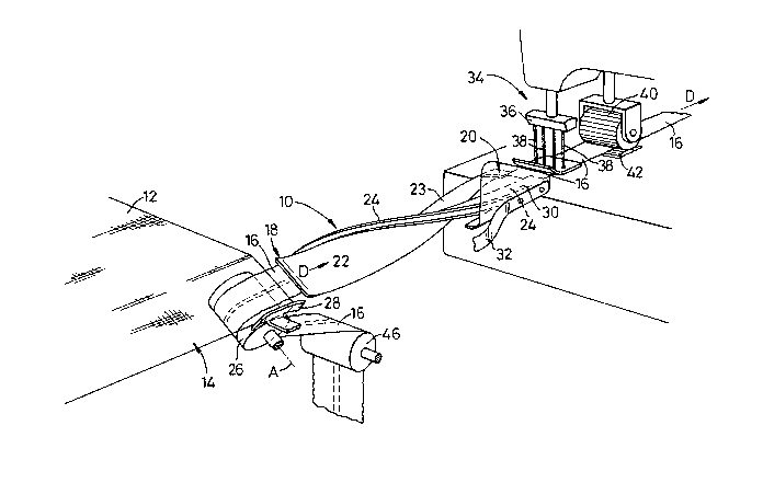
The illustrative apparatus comprises a folding device 10
for forming fabric 12 into a hem tunnel by folding a marginal
strip 14 of fabric protruding be~ond an edge of an elastic band
16 fed to the folding device 10, with a first face of the band
in contact with the first face of the fabric 12 around said edge
of the band to overlay a second, opposi-te, face of the band 16
and by folding the fabric about the other edge o the band 16 to
present a second face of the band and marginal strip 14 to the
first face of the fabric.
The folding device 10 comprises an entry zone 18 and an
exit zone 20 both of which are substantially planar. The folding
device 10 comprises two parallel members 22, 24 between which
portions of the band and fabric travel along the folding device
10. A first of the members 22 has a width substantially equal to
that of the band 16 and a turned over marginal portion 23 for
folding the strip 14 round the edge of the band. The second of
7 9
the members 24 is much narrower than the member 22 and located
adjacent one edge portion of the first member 22. The members
twist in their length through an angle of less than 180.
The apparatus further comprises a first guide roller 26 by
which the band 16 is guided to the folding~device 10. The guide
roller 26 is mounted for rotation about an axis A which is
parallel with the plane F of the entry zone of the folding
device 10 but at right angles with the direction D of feed of
material through the folding device 10. A guide 28 is positioned
adjacent the guide roller 26 against which an edge portion of
the fabric 12 may be guided when feeding the- fabric 12 into the
folding device 10. A retaining member 30 is mounted on spring
means conveniently a leaf spring 32 to aid in retaining the
folded fabric in position as it leaves the folding devic~ 10;
the spring mounting of the member 30 permits it to yield thus to
allow bulky seams to pass unrestricted, the spring 32 returning
the member 30 to its normal position.
Folding device 10, the retaining device 30 and the guide
roller 26 are all mounted on an attachment which is readily
remova~le from a sewing machine 34 adapted to secure the band in
the hem tunnel.
2~3~7~
Existing machines supplied by Automatic Braiding Limited
include attachments mounting inter alia long or short folding
devices as outlined above, the members of which twist through
180 in the length of the device. The attachments of the
existing machines are commonly inter-changed dependant on
whether or not the elastic to be incorporated in the hem tunnel
is a draw~cord elastic. The attachment of the illustrative
machine is constructed to likewise be readily exchangeable with
the existing attachments.
As can be seen from the drawings, the sewing machine
comprises a needle bar 36 carrying needles 38. The sewing
machine further comprises a pair of feed rollers 40, 42, being
so driven that the band and fabric, passing between the rollers
are withdrawn from the folding device in known manner.
The illustrative sewing machine further comprises a
metering device, viz pair of metering rollers (not shown), at
least one of which is driven, for forwarding the band at a
predetermined linear speed over an idler roller 46 to the guide
roller 26. The metering rollers are of known construction. The
idler roller 46 is also carried on the attachment for the sewing
machine, as is the guide roller 26; however the metering device
is carried on the frame of the sewing machine and is utilised
with other attachments carrying folding devices which may be
mounted on the sewing machine. In known manner, the feed of the
2~3~7~
12
material by the feed rollers 40, 42 is co-ordinated with the
reciprocation of the needle bar 36 and movement of the fee~ dog
(positioned beneath the foot of the sewing machine) and the feed
rollers 40, 42 and feed dog are driven at such a speed that the
band and fabric are withdrawn from the folding device 10 at a
greater linear speed than that at which the band 16 is forwarded
by the metering rollers so that the band 16 is in a tensioned
condition as it is secured within the hem tunnel.
In the drawings, the band 16 is shown extending through the
machine; however, a piece of garment fabric 12 is shown in a
position where it is about to enter the entry zone of the
folding device.
Figures 2 to 5 show the folding device 10 at various
positions along its length. Figure 2 is a view at the entry zone
18 while Figure 5 is a view at -the exit zone 20. The exit zone
20 is substantially planar and horizontal, as indicated by the
chain dot line P which is also parallel with the planar path of
the material leaving the folding device 10. The plane P is shown
on each of Figures 2 to 5. In Figure 2 the plane of the entry
zone 18 is indicated by the chain dot line F and as can be seen
from Figure 2 this is inclined at an angle X to the plane of the
exit zone P. The axis A of the guide roller 26 is parallel with
the plane F. In the apparatus the angle X is about 45 but this
2~3~7~
may be varied in other apparatus in accordance with the
invention, generally similar to the illustrative apparatus, as
desired.
As the length of the folding device 10 is about 16 cms,
corresponding with the length of the short folding devices of
the known machines supplied by the applicant company, whilst the
angle through which the member 22 twists along the length of the
folding device is only about 135, the severity of the twis-ting
force applied to the band 16 is less than would be the case were
the standard folding device to be used and the tendency of draw-
cord elastic to collapse is substantially eliminated. The
illustrative apparatus is easier for an operator to use when
inserting draw-cord elastic than the existing apparatus
utilising a longer folding device and can be run at a faster
speed due to the reduced resistance. Furthermore, the
illustrative attachment is less expensive than the known
attachments for dealing with draw-cord elastic satisfactorily
and a reduction in scrap can also arise.