Note: Descriptions are shown in the official language in which they were submitted.
20301~4
TITLE OF THE INVENTION
A White Balance Adjusting Apparatus for Automatically
Adjusting White Balance in Response to Luminance
Information Signal and Color Information Signal Obtained
from Image Sensing Device
BACKGROUND OF THE INVENTION
Field of the Invention
The present invention relates to white balance
adjusting apparatus, and more particularly to a white
balance adjusting apparatus in an image sensing apparatus
such as a color video camera for automatically adjusting
white balance to correct the wavelength distribution of
light differing by each light source, according to the
lllmin~nce information signal and the color information
signal within the image sensing signal obtained from an
image sensing device.
Description of the Background Art
In taking an object using an image sensing apparatus
such as a color video camera, the wavelength distribution
of light illuminating the object from a light source
differs by the type of the light source. For example, the
blue components are intensive in light from a light source
of relatively high temperature, whereas the red components
are intensive in light from a light source of relatively
low temperature. It is therefore necessary to correct the
'- 203014g
wavelength distribution of each light source in order to
properly reproduce the color tone of the object itself
illuminated with light of the light source on the screen
of a color monitor television receiver. This correction
is generally called white balance adjustment, where the
gain of each color signal is adjusted so that the ratio of
the amplitudes of the three primary color signals of red
(hereinafter referred to as R), blue (hereinafter referred
to as B), and green (hereinafter referred to as G) is
1 0 1 ~
In conventional image sensing apparatus, the
detection of the three primary color signals R, G, and B
is carried out according to light around the image sensing
apparatus using a sensor provided for each color.
However, white balance could not be adjusted correctly
with such image sensing apparatus when the light source
around the image sensing apparatus (for example,
fluorescent light) differs from the light source
illuminating the object (for example the sun), as in the
case where an outdoor scene is taken from inside a room.
Recently, a method called TTL (through-the-lens) is
proposed in which white balance adjustment is carried out,
without providing separate sensors, according to color
difference signals R-Y and B-Y within the image sensing
signal obtained from an image sensing device. Such a
203014~
method is disclosed in Japanese Patent Laying-Open No. 62-
35792, for example. This method is based on the
consideration that the object taken by an image sensing
apparatus has various color area distribution (hereinafter
referred to as the color distribution) and if this color
distribution is averaged over a sufficient long time, the
color components cancel each other to result in each color
signal of "0", which is equivalent to a state of taking a
complete white picture. By controlling the gains of
respective color signals so that the values resulting from
integration of color difference signals R-Y and B-Y over
one field period, for example, become 0 to correct the
offset of the color tone due to wavelength distribution of
light of the light source.
Fig. 1 is a block diagram showing an example of a
conventional white balance adjusting apparatus by the TTL
method. Referring to Fig. 1, light from an object (not
shown) enters an image sensing device 2 formed of a CCD
via a lens 1. The incident light is photoelectric-
converted into an electric signal and provided to a color
separating circuit 3. Color separating circuit 3 extracts
the three primary color signals of R, G, and B from this
electric signal. The extracted G signal is directly
provided to a camera processing and matrix circuit 6. The
R signal and B signal are provided to camera processing
- ~ 20301~
and matrix circuit 6 via a gain variable R amplifying
circuit 4 and a B amplifying circuit 5, respectively.
Camera processing and matrix circuit 6 creates a luminance
signal Y and color difference signals R-Y and B-Y
according to the entered three primary color signals of G,
R, and B. The outputs are provided to a video circuit 7
where luminance signal Y and color difference signals R-Y
and B-Y are subjected to the well-known process to create
a record video signal. This record video signal is
provided to a video recording circuit not shown.
The two color difference signals R-Y and B-Y are
applied to integrating circuits 18 and 17, respectively,
to be integrated over a sufficient long time, for example
over 1 field period of a video signal. The values
resulting from integration are provided to gain control
circuits 13 and 14. Gain control circuits 13 and 14
control the variable gains of B amplifying circuit 5 and R
amplifying circuit 4 so that the values resulting from
integration each becomes 0. This results in the amplitude
ratio of 1:1:1 of the three primary color signals G, R,
and B to adjust white balance.
In a conventional white balance adjusting apparatus
of Fig. 1, there are some cases where at least one of the
outputs of a plurality of light reception portions (not
shown) provided for respective colors of R, G and B and
- 203Ql ~
constituting image sensing device 2 is saturated, when
there is an object of significantly high luminance in a
portion of the image sensed picture, such as in the case
where a light source such as the sun is taken. The
S amplitude ratio of the three primary color signals R, G,
and B provided from color separating circuit 3 is not
proportional to the actual R, G and B components included
in the light source. Therefore, there was a problem that
white balance is offset in a direction not associated with
the actual light source color temperature, when white
balance was adjusted according to the not properly
proportional three primary color signals R, G, and B.
The conventional white balance adjusting apparatus of
Fig. 1 corrects the irregularity of the wavelength
distribution due to light of the light source, based on
the consideration that colors cancel each other so that
the reproduced picture can approximate a substantially
white picture if the various color distributions of the
object itself are averaged over a long period. This
method comprises an inconvenience that proper white
balance regarding the object itself could not be achieved
because the reproduced picture could not approximate a
white picture even if the color distributions of the
object included in the entire picture are averaged, when
2S the area ratio of the three primary colors within the
--5--
203Q144
picture is not equal, that is to say, when the color
distribution is not even, such as in the case where green
lawn or a blue sky occupies a large area of the picture,
or in the case where a human object wearing a red sweater
is taken in a close-up manner. If the above mentioned
white balance adjustment is applied to such an unbalanced
state of white balance, the gain will be controlled so as
to cancel the intensive color. In the case of a close-up
of a person wearing a red sweater, white balance will be
intense in blue unnecessarily which is the complementary
color of red, resulting in a problem that the color of the
object itself cannot be properly reproduced on the
reproduced screen.
Particularly, blue sky will be located in the upper
end of an image sensed picture when taken outdoors. White
balance of the entire picture will be intense in the side
of the complementary color of blue. Because there are
many cases where the blue sky is located at the upper end
of a picture, it is desirable to consider an effective
solution.
When the luminance of an object is extremely low,
each level of the three primary color signals of R, G, and
B will be reduced to aggravate the S/N ratio. This will
cause an unbalanced state of levels of signals R, G, and B
to generate color difference signals even though the
2030144
actual object is black, i.e. achromatic color. In the
conventional white balance adjusting apparatus of Fig. 1,
the gains of signals R and B will be varied to cancel
these color difference signals, whereby white balance is
intense in the complementary color side.
SUMMARY OF THE INVENTION
An object of the present invention is to provide a
white balance adjusting apparatus capable of appropriate
automatic white balance adjustment even in the case where
there is an object of extremely high luminance in the
picture.
Another object of the present invention is to provide
a white balance adjusting apparatus capable of appropriate
automatic white balance adjustment, even in the case where
the color area distribution of an object is not even.
A further object of the present invention is to
provide a white balance adjusting apparatus capable of
appropriate automatic white balance adjustment, even in
the case where there is an object of a specified color in
specified regions of the picture.
A still further object of the present invention is to
provide a white balance adjusting apparatus capable of
appropriate automatic white balance adjustment even in the
case where there is an object of extremely low luminance
in the picture.
20301~4
Briefly stated, the present invention is a white
balance adjusting apparatus for automatically adjusting
white balance according to a luminance information signal
and a plurality of color information signals obtained from
an image sensing apparatus having a lens and an image
sensing device. The white balance adjusting apparatus
includes an amplifying circuit, a region setting circuit,
luminance evaluating value and color evaluating value
converting circuit, a gain control circuit, and a weight
reducing circuit. The amplifying circuit amplifying each
of the color information signals with a corresponding
variable gain. The region setting circuit divides the
image sensed picture to set a plurality of regions on the
image sensed picture. The lllm;n~nce evaluating value and
color evaluating value converting circuit averages
lllm;n~nce information signal and respective ones of
plurality of color information signals to convert the same
into ll~m;n~nce evaluating value and color evaluating
values for each of the plurality of regions. The gain
control circuit is responsive to each color evaluating
value of each of the plurality of regions for controlling
the variable gain of the amplifying circuit. The weight
reducing circuit reduces the contribution degree of each
color evaluating value towards the control of the variable
gain in regions where the luminance evaluating value is
2030144
greater than a predetermined value.
In accordance with another aspect of the present
invention, the weighing amount regarding the color
evaluating values of each region is determined according to
the luminance information signal of each region.
In accordance with a still further aspect of the
present invention, the contribution degree towards variable
gain control of color evaluating values in the corresponding
specified regions is reduced, when the luminance evaluating
value and the color evaluating value of a specified color in
specified regions of the image sensed picture are greater
than the respective predetermined values.
In accordance with another aspect of the present
invention, the contribution degree towards variable gain
control of each color evaluating value is reduced, in
regions where the contrast evaluating value indicating the
contrast of an object is smaller than a predetermined value.
In accordance with a further aspect of the present
invention, the control of variable gain is limited according
to the luminance information signal.
Accordingly, in one aspect, the present invention
relates to a white balance adjusting apparatus for
automatically adjusting white balance in response to a
luminance information signal and a plurality of color
information signals obtained from imaging sensing means
having a lens and an image sensing device, comprising:
means for amplifying each of said color information
203014~
signals with a corresponding variable gain so as to yield a
corresponding plurality of amplified color information
signals,
means for dividing a picture produced by said image
sensing device into a plurality of regions,
means for integrating said luminance information
signal and respective ones of said plurality of amplified
color information signals to convert said luminance
information signal and said amplified color information
signals into a luminance evaluating value and color
evaluating values, respectively, for each of said plurality
of regions,
means for controlling the variable gain of said
amplifying means according to each of said color evaluating
values of each of said plurality of regions, and
means for adjusting each of said color evaluating
values in response to said luminance evaluating value.
In a further aspect, the present invention relates to
a white balance adjusting apparatus for automatically
adjusting white balance in response to a luminance
information signal and a plurality of color information
signals obtained from image sensing means having a lens and
an image sensing device, comprising:
means for amplifying each of said color information
signals with a corresponding variable gain so as to yield a
corresponding plurality of amplified color information
signals,
-9a-
2030144
means for dividing a picture produced by said image
sensing device into a plurality of regions,
means for integrating said luminance information
signal and respective ones of said plurality of amplified
color information signals so as to convert said luminance
information signal and said amplified color information
signals into a luminance evaluating value and color
evaluating values, respectively, for each of said plurality
of regions,
means for controlling the variable gain of said
amplifying means according to each of said color evaluating
values within each of said plurality of regions, and
means, operative in conjunction with said variable
gain controlling means, for reducing a contribution degree
of each of said color evaluating values in specified
regions, for control of said variable gain, when the
luminance evaluating value and a specified color evaluating
value in said specified regions are greater than respective
predetermined values.
In a still further aspect, the present invention
relates to a white balance adjusting apparatus for
automatically adjusting white balance in response to a
luminance information signal and a plurality of color
information signals obtained from image sensing means having
a lens and an image sensing device, comprising:
means for amplifying each of said color information
signal by a corresponding variable gain so as to yield a
-9b-
,, . Y~ ,~
,
2030144
corresponding plurality of color information signals,
means for dividing a picture produced by said image
sensing device into a plurality of regions,
means for integrating each of said plurality of
amplified color information signals so as to convert said
amplified color information signals into a color evaluating
value for each of said plurality of regions,
means, operative in response to said luminance
information signal, for extracting a high frequency
component from said luminance information signal so as to
form an extracted level and, in response to said extracted
level, generating a contrast evaluating value indicative of
contrast for each of said plurality of regions,
means for controlling the variable gain of said
amplifying means according to each of said color evaluating
values within each of said plurality of regions, and
means, operative in conjunction with said variable
gain controlling means, for reducing a contribution degree
of each of said color evaluating values, for control of said
variable gain, in regions where said contrast evaluating
value is smaller than a predetermined value.
In a further aspect, the invention relates to a white
balance adjusting apparatus for automatically adjusting
white balance in response to a luminance information signal
and a plurality of color information signals obtained from
image sensing means having a lens and an image sensing
device, comprising:
--9c--
2030144
means for amplifying each of said color information
signals with a corresponding variable gain so as to yield a
corresponding plurality of amplified color information
signals,
means for integrating each of said plurality of
amplified color information signals so as to yield an
integrated color information signal,
means, responsive to said integrated color information
signals, for controlling the variable gain of said
amplifying means according to said integrated color
information signal,
means for limiting the control of said variable gain
according to said luminance information signal,
means for integrating said luminance information
signal so as to yield an integrated luminance information
signal, and
means for setting an upper limit of the control amount
of said variable gain according to said integrated luminance
information signal.
In a still further aspect, the present invention
relates to a white balance adjusting apparatus for
automatically adjusting white balance in response to a
luminance signal and a plurality of color difference
signals, comprising:
means for amplifying each of a plurality of color
signals produced by an image sensing device with a
corresponding variable gain so as to yield a corresponding
9d-
203014~1
plurality of amplified color signals,
means for dividing a picture produced by said image
sensing device into a plurality of regions,
means for converting said plurality of amplified color
signals into said luminance signal and said plurality of
color difference signals,
means for integrating said luminance signal and
respective ones of said plurality of color difference
signals so as to convert the luminance signal and the color
difference signals into a luminance evaluating value and
color evaluating values, respectively, for each of said
plurality of regions,
means for controlling the variable gain of said
amplifying means according to each of said color evaluating
values within each of said plurality of regions, and
means, operative in conjunction with said variable
gain controlling means, for reducing a contribution degree
of each of said color evaluating values, for control of said
variable gain, in regions where said luminance evaluating
value is greater than a predetermined value.
A main advantage of the present invention lies in that
unnecessary offset of white balance of the picture is
prevented even in the case where there is an object of
2030144
high luminance in the picture.
Another advantage of the present invention lies in
that white balance can be suppressed from being intense in
the complementary color of the object, even in the case
where the color area distribution of the object in the
picture is not even.
A further advantage of the present invention lies in
that white balance is not offset to cancel the
corresponding specified color even in the case where an
object of the specified color exists in the specified
regions in the picture.
A still further advantage of the present invention
lies in that unnecessary offset of white balance of the
picture is suppressed even when there is an object of
extremely low luminance in the picture.
The foregoing and other objects, features, aspects
and advantages of the present invention will become more
apparent from the following detailed description of the
present invention when taken in conjunction with the
accompanying drawings.
BRIEF DESCRIPTION OF THE DRAWINGS
Fig. 1 is a block diagram of an example of a
conventional white balance adjusting apparatus.
Fig. 2 is a block diagram of a white balance
adjusting apparatus of a first embodiment of the present
--10--
20301~4
invention.
Fig. 3 is a diagram schematically showing the
specified regions on the image sensed picture.
Fig. 4 is a block diagram showing the integrator of
Fig. 2 in detail.
Fig. 5A is a block diagram showing the color
evaluating value adjusting circuit of Fig. 2 in detail.
Fig. 5B is a block diagram showing another color
evaluating value adjusting circuit of Fig. 2.
Fig. 6 is a block diagram showing a white balance
adjusting apparatus of a second embodiment of the present
invention.
Fig. 7 is a block diagram showing a white balance
adjusting apparatus of a third embodiment of the present
invention.
Fig. 8 is a block diagram showing the color
evaluating value adjusting circuit of Fig. 7 in detail.
Fig. 9 is a block diagram showing another example of
a color evaluating value adjusting circuit of Fig. 7.
Fig. 10 is a block diagram showing a white balance
adjusting apparatus of a fourth embodiment of the present
invention.
Fig. 11 is a block diagram of the color evaluating
value adjusting circuit of Fig. 10 in detail.
Fig. 12 is a schematic diagram for explaining the
2030144
operation principle of the fourth embodiment of Fig. 10.
Fig. 13 is a block diagram showing another example of
the color evaluating value adjusting circuit of Fig. 10.
Fig. 14 is a block diagram of a white balance
adjusting apparatus of a fifth embodiment of the present
invention.
Fig. 15 is a graph for explaining the operation of
the fifth embodiment of the Fig. 14.
Fig. 16 is a block diagram showing a white balance
adjusting apparatus of a sixth embodiment of the present
invention.
Fig. 17 is a graph explaining the operation of the
sixth embodiment of Fig. 16.
DESCRIPTION OF THE PREFERRED EMBODIMENTS
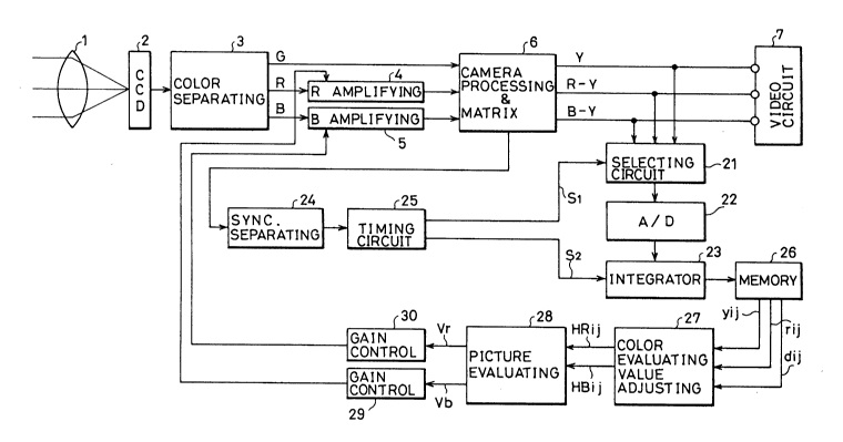
Fig. 2 is a block diagram showing a white balance
adjusting apparatus of a first embodiment of the present
invention. Referring to Fig. 2, light from an object (not
shown) enters an image sensing device 2 formed of a CCD
via a lens 1. The incident light is photoelectric-
converted into an electric signal and applied to a color
separating circuit 3. Color separating circuit 3 extracts
the three primary color signals of R, G and B from the
electric signal. The extracted G signal is directly
provided to a camera processing and matrix circuit 6,
whereas signals R and B are provided to camera processing
-12-
20301~ 1
and matrix circuit 6 via a gain variable R amplifying
circuit 4 and a B amplifying circuit 5, respectively.
Camera processing and matrix circuit 6 produces luminance
signal Y and color difference signals R-Y and B-Y
according to the entered three primary color signals of G,
R and B, and provides the outputs to a video circuit 7.
The well-known processing are carried out to luminance
signal Y, and to color difference signals R-Y and B-Y in
video circuit 7 to produce a record video signal. This
signal is provided to a recording circuit not shown.
Simultaneously, each of signals Y, R-Y, and B-Y is
provided to a selecting circuit 21. Selecting circuit 21
is responsive to a selection signal S1 produced by a
timing circuit 25 according to a vertical synchronizing
signal provided from a synchronizing separating circuit
24, to sequentially select one signal out of luminance
signal Y, color difference signal R-Y, and color
difference signal B-Y for each 1 field. In the embodiment
of Fig. 2 for example, the luminance signal or the color
difference signal is selected for each field in the order
of (Y) - (R-Y) - (B-Y) - (Y) - (R-Y) - ... . The
selected signal is provided to the succeeding stage A/D
converter 22.
A/D converter 22 samples one of signals Y, R-Y, and
B-Y selected by selecting circuit 21 with a predetermined
203014~
sampling period to convert into a digital value. The
converted value is provided to an integrator 23.
Meanwhile, timing circuit 25 produces a switching
signal S2 according to vertical and horizontal
synchronizing signals provided from camera processing and
matrix circuit 6, and the fixed output of an oscillator
(not shown) for driving CCD 2. Switching signal S2 is
provided to integrator 23. Integrator 23 is responsive to
switching signal S2 to divide the image sensed picture
into 8 x 8 = 64 rectangular regions A~l, Al2, A~3, .. , ~j
(i, j = an integer of 1-8) each of an identical area, for
deriving the output of selecting circuit 21 in time
divisional manner for each region.
More specifically, integrator 23 receives switching
signal S2 to add the A/D converted values output from
selecting circuit 21 over 1 field period for each region,
i.e., digital-integrate the output of selecting circuit 21
for each region of the 64 regions, to hold the digital-
integrated value corresponding to each region as a
luminance evaluating value, or a color evaluating value in
memory 26, after integration within 1 field period is
completed. The digital-integrated value of luminance
signal Y corresponding to respective ones of the 64
regions are obtained as 64 luminance evaluating values Yi~
(i, j:l-8) in an arbitrary field. In the next field where
-14-
20301~-1
color difference signal R-Y is selected by selecting
circuit 21, the digital-integrated values for respective
regions of the color difference signal R-Y are obtained as
64 color evaluating values ri~ as a result of integration
for respective regions by integrator 23. At a further
next field where color difference signal B-Y is selected
by selecting circuit 21, the digital-integrated value for
respective regions of color difference signal B-Y are
obtained as 64 color evaluating values bij as the result of
integration for respective regions by integrator 23.
When integration of luminance signal Y, and color
difference signals R-Y and B-Y over 3 field periods is
completed, a total 64 x 3 = 192 of luminance evaluating
value Yi; and color evaluating values rij and bij are held in
memory 26. Similar operation is repeated where a new
luminance evaluating value Yij is applied to memory 26 at
the next field. At a further next field, color evaluating
value rij is applied to memory 26. The luminance
evaluating value and color evaluating values held in
memory 26 are sequentially updated.
Fig. 4 is a block diagram of integrator 23 in detail.
Each A/D converted data provided from A/D converter 22 is
provided to a switching circuit 61. Switching circuit 61
receives switching signal S2 from timing circuit 25 for
providing each A/D converted value into an adder provided
20301g4
corresponding to the region where the sampling point of
the corresponding A/D converted data exists, out of the 64
adders Fll, Fl2, .., F88 provided corresponding to the 64
regions All, Al2, -- , A88 . For example, if a sampling
point of an arbitrary A/D converted data is included in
region All, switching circuit 61 provides this data to
adder Fll corresponding to region All.
In the succeeding stage of each adder Fi;, a holding
circuit Qi; is provided, where the output of each adder is
first held in the corresponding holding circuit. The data
held in each holding circuit is applied to a corresponding
adder again and added with the next applied A/D converted
data. Although each holding circuit Qi; is reset by each 1
field in response to a vertical synchronizing signal, only
the data held immediately before reset is provided to
memory 26. Thus, one digital integrating circuit is
composed of one set of an adder and a holding circuit.
Integrator 23 is composed of a total of 64 digital
integrating circuits. This means that a digital-
integrated value corresponding to each of 64 regions isapplied to memory 26 from the holding circuit for each
field.
The reference level, i.e. the 0 level, of each of the
two color difference signals R-Y and B-Y provided to A/D
converter 22 is set in advance to a level obtained when a
-16-
203014~
complete achromatic color picture is taken. Therefore,
the value obtained by A/D converting the color difference
signal may take not only a positive value, but a negative
value.
Referring to Fig. 2 again, the latest Yij, rij, bi;
calculated as in the above manner and held in memory 26
are provided to color evaluating value adjusting circuit
27. Color evaluating value adjusting circuit 27 makes
determination as to whether the level of luminance
evaluating value Yi; of each region exceeds a predetermined
value or not. When exceeding a predetermined value, the
level of the color evaluating values of the corresponding
region are reduced by a predetermined amount P.
Fig. 5A is a block diagram of color evaluating value
adjusting circuit 27. Referring to Fig. 5A, luminance
evaluating value Yij Of each region is provided to
luminance comparator 41, to be compared with a luminance
threshold value Ny stored in advance in a luminance
threshold value memory 40. Comparator 41 generates
switching signal S of the H level when luminance
evaluating value Yi; is equal or greater than threshold
value Ny~ and of the L level, when less than threshold
value N9. The output is provided to switching circuit 42.
This luminance threshold value Ny is set according to an
experiment in advance as a threshold value for identifying
2030141
that any of the outputs of light reception portions of
respective colors of R, G, and B of the image sensing
device is saturated.
Switching circuit 42 is implemented with two switches
43 and 44. Switch 43 functions to selectively connected a
fixed contact 43a to which color evaluating value ri; is
applied to a fixed contact 43b coupled to R attenuator 45
or a fixed contact 43c coupled to output terminal 47.
Switch 44 functions to selectively connected a fixed
contact 44a to which color evaluating value bij is applied
to a fixed contact 44b coupled to B attenuator 46 or a
fixed contact 44c coupled to output terminal 48.
Both switches 43 and 44 are controlled by switching
signal S from luminance comparator 41. When switching
signal S is at the L level, switches 43 and 44 are turned
to the sides of fixed contacts 43c and 44c, where color
evaluating values ri; and bij are directly provided to
output terminals 47 and 48 as adjusted color evaluating
values HRi; an HBij, respectively. When switching signal S
is at the H level, switches 43 and 44 are turned to the
sides of fixed contact 43b and 44b, where color evaluating
values ri; and bi; are provided to R and B attenuators 45
and 46.
R and B attenuators 45 and 46 subtract a
predetermined constant amount P from the provided color
20301~
evaluating values r1~ and b,~ to calculate ri~ - P and b~ -
P. This is provided to output terminals 47 and 48 as
adjusted color evaluating values HRi~ and HBL~,
respectively. The constant amount P is a value obtained
from an experiment in advance that can sufficiently
identify that the picture quality is not unnatural when an
object of high luminance is taken.
Referring to Fig. 5A, the operation of color
evaluating value adjusting circuit 27 is explained
hereinafter. When luminance evaluating value Ylj of a
region is provided to color evaluating value adjusting
circuit 27, this luminance evaluating value Yi~ is compared
with luminance threshold value Ny by luminance comparator
41. When luminance evaluating value YL~ is greater than
the threshold value, determination is made that the object
in the region is of high luminance to provide switching
signal S of the H level to switching circuit 42. As a
result, color evaluating values rij and bi; are attenuated
by a constant amount P by R and B attenuators 45 and 46 to
be provided from output terminals 47 and 48. When
luminance evaluating value Yij is smaller than threshold
value Ny~ determination is made that the object is not of
high luminance, and color evaluating values ri~ and bi~ are
not attenuated and directly provided from output terminals
47 and 48. Only the color evaluating values of the region
--19--
-
2030144
where an object of high luminance exists are attenuated.
The attenuated or not attenuated color evaluating
values HR1~ and HBL; provided from output terminals 47 and
48 are provided to picture evaluating circuit 28 of Fig.
2, where color evaluating values of the entire picture
regarding respective color different signals are
calculated as picture color evaluating values Vr and Vb,
according to the following equations (1) and (2).
8 8
Vr = ~ ~ HRij/64 ... (1)
i=j j=l
8 8
Vb = ~ ~ HBij/64 ... (2)
i=j j=l
By equations (1) and (2), the average value of one
region is derived as a picture color evaluating value
which is a color evaluating value of the entire picture,
by dividing the total sum of the adjusted color evaluating
values of the 64 regions provided from color evaluating
value adjusting circuit 27 by the total number of regions.
Gain control circuits 29 and 30 control the gains of
R amplifying circuit 4 and B amplifying circuit 5 so that
both picture color evaluating values Vr and Vb become 0.
When picture color evaluating values Vr and Vb becomes 0,
white balance adjustment is completed.
Although the color evaluating value itself is
directly corrected according to the adjusting process by
-20-
- 20301~4
color evaluating value adjusting circuit 27 in the
embodiment of Fig. 2, it is possible to obtain similar
results by weighting color evaluating values with a
constant weighing amount in general state, and only
reducing the weighing amount regarding color evaluating
values of high luminance.
Fig. 5B is a block diagram showing another example of
color evalauting value adjsuting circuit 27.
Regarding regions other than the high luminance
regions, a predetermined weighting amount Dl is weighted
on color evaluating values by weighting circuits 56 and
58, that is to say, the multiplication of rij x Dl and b~ x
D1 are carried out. Regarding regions of high luminance,
weighting amount D2 smaller than weighting amount D1 is
weighted by weighting circuits 55 and 57, that is to say,
the multiplication of rij x D2 and bij x D2 are carried out.
By providing these multiplied values as the modified color
evaluating values of each region, it is possible to reduce
the contribution degree towards white balance adjustment
of the entire picture regarding regions satisfying the
condition of Yi; > N9.
According to the first embodiment of the present
invention, it is possible to prevent offset of white
balance adjustment to achieve appropriate white balance
adjustment, by reducing the contribution degree of color
203U14~
evaluating values of high luminance portions towards white
balance adjustment, even in the case where a scene
including a portion having high luminance not suitable for
white balance adjustment is taken.
Fig. 6 is a block diagram of a white balance
adjusting apparatus according to a second embodiment of
the present invention. The second embodiment of Fig. 6 is
identical to the first embodiment of Fig. 2, except for
the following points. That is to say, a picture
evaluating circuit 50 is provided instead of color
evaluating value adjusting circuit 27 and color evaluating
circuit 28 of Fig. 2.
Picture evaluating circuit 50 of Fig. 6 fetches the
latest evaluating values Yij, rij, and bij (i, j:1-8) from
memory 26 to calculate the color evaluating values of the
entire picture regarding color difference signals R-Y and
B-Y as picture color evaluating values Vr and Vb, according
to the following equations (3) and (4).
8 8 8 8
Vr = ~ ~ (ri; x Yij) / ~ ~ Yij -.(3)
i=j j=l i=j j=l
8 8 8 8
Vb = ~ ~ (bi~X Yij) / ~ ~ Yi; -.(4)
i=j j=1 i=j j=1
The above equations will be explained hereinafter
briefly. Equations (3) and (4) are equations multiplying
and summing color evaluating values ri; and bi~ of
-
2030144
respective color difference signals by luminance
evaluating value Yij/ considering that chroma is higher in
portions where the luminance level is high, and likely to
be white. In the above equation (3),
8 8
~ ~ (rij x Yij)
i=l j=l
is the total sum of the multiplication results of all 64
regions upon applying weight to color evaluating value r
of color difference signal R-Y in proportion to the
luminance level, by multiplying color evaluating value ri;
of the 64 regions by the corresponding luminance
evaluating value Yij-
However, normalization of the weighing amount is not
carried out only with the above
8 8
~ ~ (ri; x Yi;)
i=l j=l
That is to say, the factor that a region having high
luminance level occupies a large area in the picture will
increase the color evaluating values of the entire screen.
Hence, normalization of the weighing amount is
carried out by dividing the above mentioned total sum of
8 8
~ ~ (ri; x Yij)
i=l j=l
by the total sum of
-
2030144
8 8
~ ~ Y
i=l j=l
which is the total sum of the weighing amount of all
regions. By multiplying and summing color evaluating
value r1~ of the color difference signal over the entire
picture using weighing amount Yi;l a picture color
evaluating value Vr having area factors removed is derived.
In a situation where half of the regions forming an
image sensed picture, i.e., 32 regions of the 64 regions,
have an object of color evaluating value ri~ = 10 of color
difference signal R-Y and luminance evaluating value Yi~ =
10, with the remaining 32 regions completely of black
color (Yi; = 0), the following total sum is obtained:
8 8
~ ~ (rij x Yij) = 10 x 10 x 32 = 3200
i=1 j=l
Therefore, if normalization is not carried out with the
weighing amount, the color evaluating value of the entire
picture is calculated as 3200, whereby white balance
adjustment is carried out according to this value.
Assuming another situation where an object identical
to the above mentioned object, i.e. an object of rij = 10
and Yij = 10, exists in regions corresponding to lJ4 of the
image sensed picture, i.e. in 16 regions, and the
remaining regions are completely black, the following
-24-
20301~4
total sum is derived:
8 8
(ri~ x Yi;) = 10 x 10 x 16 = 1600
i-- ]_
Because the object is completely identical and the
regions where the object does not exist is completely a
black level in either of the two situations, white balance
adjustment must be carried out with respect to the
identical object in either case. This means that the
white balance adjustment amount must be the same adjusting
amount even if the area ratio occupied by the object in
the image sensed picture differs. There must not be
difference regarding picture color evaluating values
according to the area ratio of the high luminance level
regions in the picture, such as the above 3200 and 1600.
By dividing 3200 and 1600 by
-25-
2o3ol~4
8 8
~ ~ Yi; = 10 x 32 - 320 and
i=l j=l
8 8
~ ~ Yi~ = 10 x 16 = 160, respectively, for
i=1 j=1
normalization by the total weighing amount, picture
evaluating value Vr will become Vr = 3200/320 = 1600/160 =
10 in either case, to adjust white balance with identical
adjusting amount regarding R components.
Similarly, the above equation (4) can derive the
normalized color evaluating value of the entire picture as
picture color evaluating value Vb, by adding and
multiplying color evaluating value bi; of color difference
signal B-Y of each region over the entire picture by
luminance evaluating value Yij.
Referring to Fig. 6 again, gain control circuits 29
and 30 control the respective gains of R amplifying
circuit 4 and B amplifying circuit 5 so that picture color
evaluating values Vr and Vb both become 0 which are the
color evaluating values regarding the entire picture.
When picture color evaluating values Vr and Vb become 0,
white balance adjustment is completed.
According to the second embodiment of the present
invention, it is possible to suppress the offset of white
balance to the complementary color side to improve the
203014~
reproduction of the actual color of the object, by
increasing the effect of color signals in regions of high
luminance probably white towards white balance adjustment,
even when the color distribution of the image sensed
picture is not even.
Fig. 7 is a block diagram showing a third embodiment
of the present invention. The third embodiment of Fig. 7
is the same as the first embodiment of Fig. 2, except for
the following points. That is to say, a color evaluating
value adjusting circuit 60 is provided instead of color
evaluating value adjusting circuit 27 of Fig. 2.
Evaluating values Yijl rij, bij held in memory 26 are
provided to color evaluating value adjusting circuit 60.
Color evaluating value adjusting circuit 60 makes
determination whether an object having a particular
luminance level and a specified color exists in the
specified regions previously selected out of the 64
regions. When such an object exists, the color evaluating
value level of the corresponding region is reduced by a
predetermined amount Z.
In general, there is high probability that blue sky
is located at the upper side of the image sensed picture
when taken outdoors. Blue sky is an object in which the
ll~m; n~nce level is relatively high and which color
difference signal B-Y is significantly high. It is
-27-
203V14~
probable that the picture will be intense in the blue
components considering the entire picture. In the third
embodiment, the 16 regions in the 2 topmost rows of the
picture are selected as the specified regions with blue as
the specified color.
Fig. 8 is a block diagram of the color evaluating
value adjusting circuit 60 of Fig. 7.
Referring to Fig. 8, luminance evaluating value y~ of
each region is applied to luminance comparator 62 from the
topmost region in the order of Yll ~ Yl2 ~ -- Yls ~ Y21 ~
... ~ Y88~ to be compared with luminance threshold value ny
stored in luminance threshold value memory 63 in advance.
The comparison operation by luminance comparator 62 is
carried out only when the luminance evaluating value from
the region selected in advance by region selecting circuit
64 is applied. In the third embodiment, the above
mentioned blue sky is recognized as an object of the
specified color, where the regions specified by region
selecting circuit 64 are set to 16 regions A1l, A12 -- A28
corresponding to the topmost 2 rows of the image sensed
picture. Therefore, the comparison operation by lllmin~nce
comparator 62 is carried out with respect to only the
luminance evaluating values of the 16 regions. As a
result of the comparison operation, comparison signal S3
of a H level associated with the corresponding region is
20301~4
generated from luminance comparator 62, when determination
is made that luminance evaluating value Yi; is greater than
luminance threshold value ny.
Color comparator 65 compares the levels of color
evaluating value bij and B threshold value Nb stored in
color threshold value memory 166, only when comparison
signal S3 is at the H level. Only the color evaluating
values bi; of the regions where the luminance evaluating
value is determined to be greater than luminance threshold
value ny by comparison of luminance comparator 62 will be
compared with B threshold value Nb. As a result of the
comparison operation, comparison signal S4 of a H level is
generated regarding the corresponding region from color
comparator 65 only when color evaluating value bi~ is
greater than B threshold value Nb.
Referring to Fig. 8, switching circuit 66 is
constituted by two switches 67 and 68. Switch 67
functions to selectively connect a fixed contact 67a to
which color evaluating value bij is applied to a fixed
contact 67b coupled to B attenuator 69 or a fixed contact
67c coupled to output terminal 71. Switch 68 functions to
selectively connect a fixed contact 68a to which color
evaluating value ri; is applied to a fixed contact 68b
coupled to R attenuator 70 or a fixed contact 68c coupled
to output terminal 72.
-29-
20301~
Switches 67 and 68 are switch controlled
synchronously with comparison signal S4 as a switching
signal. When comparison signal S4 is at the L level,
switches 67 and 68 are switched to the sides of fixed
contacts 67c and 68c, where color evaluating values bi~ and
rij of the corresponding region are directly provided to
output terminals 71 and 72 without being attenuated. When
switching signal S4 is at the H level, switches 67 and 68
are switched to the sides of fixed contact 67b and 68b,
respectively, where color evaluating values bL; and r~ of
the corresponding region are applied to B and R
attenuators 69 and 70, respectively.
B and R attenuators 69 and 70 subtract a
predetermined amount Z from the applied color evaluating
lS values bij and ri; to derive bi~ -Z and ri; -Z. The results
are provided to output terminals 71 and 72.
Regarding regions All, Al2, ..., A2B selected in
advance, color evaluating value adjusting circuit 60 makes
the determination as whether:
(I) the object has sufficient lllmi nAnce level where
luminance evaluating value YLi (i = 1, 2:j = 1-8) is
greater than luminance threshold value ny,
and also
(II) the object has significantly intensive blue
components, where color evaluating value bi; (i = 1, 2:j =
-30-
20301~4
1-8) is greater than B threshold value Nb,
where evaluating value adjusting operation is carried
out to attenuate color evaluating values bL; and rL; by a
predetermined amount Z regarding the region satisfying
both (I) and (II).
Luminance and color evaluating values YLj, bL~, and r
are provided to color evaluating value adjusting circuit
60 synchronously from memory 26 for every identical
region. The operation within color evaluating value
adjusting circuit 60 is carried out sequentially for all
the 64 regions.
Threshold values ny and Nb are values set according to
observation data for recognizing blue sky. The
attenuating amount Z is a value set according to an
observation value where appropriate white balance is
implemented in an image sensing state having blue sky in
the selected regions of All, -- , A28-
The attenuated or not attenuated color evaluatingvalues b1~ and rL~ provided form output terminals 71 and 72
are applied to picture evaluating circuit 28, where the
color evaluating values of the entire picture regarding
respective color difference signals are calculated as
picture color evaluating value Vr and Vb according to the
following equations (5) and (6).
-31-
-
2030141~
8 8
vr = ~ ~ r~j/64 ... (5)
i=l j=l
8 8
Vb = ~ ~ bij/64 ... (6)
i=l j=l
According to equations (5) and (6), the total sum of
each of the adjusted color evaluating values rij and bi~ of
the 64 regions provided from color evaluating value
adjusting circuit 60 is divided by the number of regions
to derive the average value of one region as the color
evaluating value which is the color evaluating values
concerning the entire picture.
Gain control circuits 29 and 30 control each gain of
R amplifying circuit 4 and B amplifying circuit 5 so that
picture color evaluating values Vr and Vb both become 0.
When picture evaluating values Vr and Vb both become 0,
white balance adjustment is completed.
According to the third embodiment of the present
invention, specified regions are set in the upper side of
the picture and blue is selected as the specified color.
The effect of blue components of the blue sky towards
white balance adjustment can be suppressed to prevent
white balance of the entire picture from being intense in
the complementary color side of blue, even when blue sky
exists in the image sensed picture. The specified region
and the specified color can be selected arbitrarily. For
-32-
203014i
example, it is possible to suppress the effect of red
components of a sunset towards white balance adjustment to
prevent white balance from being intense in the
complementary color of red, by setting the specified
regions in the upper side of the picture and select red as
the specified color, and by applying color evaluating
value rij instead of bij to color comparator 65 of Fig. 8.
Fig. 9 is a block diagram showing another example of
the color evaluating value adjusting circuit 60 of Fig. 7.
In the embodiment of Fig. 8, an approach was shown where a
predetermined attenuating amount Z is subtracted from
color evaluating values ri; and bij as an example of
adjusting operation of color evaluating values in color
evaluating value adjusting circuit 60. In the embodiment
of Fig. 9, an approach is employed where a variable
weighting amount is used.
Regarding regions where comparison signal S4 is at
the L level, a predetermined weighting amount Dl' is
weighted on color evaluating values by weighting circuits
101 and 103, that is to say, the multiplication of ri; x
D1~ and bi~ x Dl' are carried out. Regarding regions
having H level comparison signal S4, weighting amount D2'
smaller than weighting amount D1' is weighted by weighting
circuits 100 and 102, that is to say, the multiplication
of ri~ x D2' and bi; x D2' are carried out. By providing
-33-
20301~4
there multiplied values as the modified color evaluating
values of each region, it is possible to reduce the
contribution degree towards white balance adjustment of
the entire picture regarding regions satisfying both the
conditions Of Yij ~ ny and bi; > Nb.
It is possible to adjust proper white balance under
various imaged sensing situations by implementation of
selection of the specified region and color by an
operation button of the operator.
According to the third embodiment of the present
invention, the luminance degree towards white balance
adjustment is reduced in situations where an object of the
specified color exists in the specified regions to
suppress white balance from being intense in the
complementary side of a particular color.
Fig. 10 is a block diagram showing a white balance
adjusting apparatus of a fourth embodiment of the present
invention. The fourth embodiment of Fig. 10 is identical
to the first embodiment of Fig. 2 except for the following
points. That is, luminance signal y provided from camera
processing and matrix circuit 6 is provided to a high pass
filter (HPF) 31, where only the high frequency component
YH is extracted and provided to selecting circuit 21.
High frequency component YH increases in proportion to the
2S contrast of the picture, that is to say, is great at the
-34-
20301~4
boundaries of objects in the picture. High frequency
component YH is reduced as the contrast of the picture is
lowered, that is to say, is low in portions of single
color in the image sensed picture.
Selecting signal 21 is responsive to selection signal
S1 produced in timing circuit 25 according to the vertical
synchronizing signal provided from synchronizing
separating circuit 24 to sequentially select any of
luminance high frequency component YH, color difference
signal R-Y amd color difference signal B-Y for each 1
field. For example, in the embodiment of Fig. 10, the
luminance high frequency component or the color difference
signals is selected by 1 field in the order of (YH) - (R-
Y) - (B-Y) - (YH) - (R-Y) - ... , where the output is
provided to A/D converter 22 of the succeeding stage.
A/D converter 22 samples signal YH or R-Y or B-Y
selected by selecting circuit 21 by a predetermined
sampling period to convert the same into a digital value.
This digital value is provided to integrator 23.
Integrator 23 receives switching signal S2 to add the
A/D converted values provided from selecting circuit 21
over 1 field period for every region, that is to say,
digital-integrate the output of selecting signal 21 for
the 64 regions. The digital-integrated value
corresponding to each region is held in memory 26 as the
-35-
2030144
contrast evaluating value or color evaluating value, when
the integration over 1 field period is completed. As a
result, the digital-integrated values of luminance high
frequency band component YH corresponding to respective
ones of 64 regions of an arbitrary field are obtained as
64 contrast evaluating values Y'i~ (i,j:1-8). In the next
field, color difference signal R-Y selected by selecting
circuit 21 is integrated by integrator 23 for respective
regions, where the digital-integrated values of color
difference signal R-Y of respective regions are obtained
as 64 color evaluating values rL;. In the next field,
color difference signal B-Y selected by selecting circuit
21 is integrated by integrator 23 for respective regions,
where the digital-integrated values of color difference
signal B-Y for respective regions are obtained as 64 color
evaluating values bij.
Thus, a total of 64 x 3 = 192 of the contrast
evaluating values Y'i; and color evaluating values ri~ and
bij are held in memory 26, when integration over 3 field
periods regarding luminance high frequency component YH,
color difference signal R-Y, and color difference signal
B-Y is completed. Similar operation is repeated, where a
new contrast evaluating value Y'ij is provided to memory 26
at the next field, and color evaluating value ri; is
5 provided to memory 26 are at a further next field. The
-36-
203014~
contrast evaluating value and color evaluating values heldin memory 26 are updated sequentially. The latest
evaluating values Y'ij~ ri~, bLj calculated in the above
manner and held in memory 26 are provided to color
evaluating value adjusting circuit 95 of the succeeding
stage.
Color evaluating value adjusting circuit 95 functions
to make determination whether an object of single color
exists or not in each region according to the magnitude of
the contrast evaluating value. That is to say, color
evaluating value adjusting circuit 95 functions to
attenuate color evaluating values ri; and bij of the
corresponding region for reducing the contribution degree
of the corresponding region towards white balance
adjustment regarding region where the contrast evaluating
value is low.
Fig. 11 is a block diagram of color evaluating value
adjusting circuit 95. Referring to Fig. 11, contrast
evaluating value Y'ij Of each region is applied to a
contrast comparator 80 starting from the top row region in
the order of Y'11 ~ Y'12 ~ ... , Y'18/ Y'21 ~ -- ~ y~ss/ to
be sequentially compared with contrast threshold value N
stored in a threshold value memory 81 in advance. When
contrast evaluating value Y'ij is smaller than contrast
threshold value N, comparison signal S5 of a H level is
.
, 20301~4
generated and provided to switching circuit 82.
Switching circuit 82 is constituted by two switches
83 and 84. Switch 83 functions to selectively connect a
fixed contact 83a to which color evaluating value rij is
applied to a fixed contact 83b coupled to R attenuator 85
or a fixed contact 83c coupled to output terminal 87.
Switch 84 functions to selectively connect a fixed contact
84a to which color evaluating value bij is applied to a
fixed contact 84b coupled to B attenuator 86 or a fixed
contact 84c coupled to output terminal 88. Switches 83
and 84 are switching controlled synchronously with
switching signal S5 from contrast comparator 80. When
switching signal S5 is at the L level, switches 83 and 84
are switched to the sides of fixed contacts 83c and 84c,
respectively, where the color evaluating values rij and bij
of the corresponding region are provided to output
terminals 87 and 88 without being attenuated. When
switching signal S5 is at the H level, switches 83 and 84
are switched to the sides of fixed contacts 83b and 84b,
respectively, where color evaluating values ri; and bij of
the corresponding region are provided to R and B
attenuators 85 and 86.
R and B attenuators 85 and 86 subtract a
predetermined amount Z~ from the applied color evaluating
values ri; and bij to calculate rij - Z' and bij - Z'. The
-38-
2d301~
result is provided to output terminals 87 and 88.
Contrast threshold value N is a value set according
to observation values for recognizing an object of single
color. The attenuating amount Z' is a value set according
to observation values when appropriate white balance is
obtained where an object of single color occupies a large
area in the picture.
The attenuated or not attenuated color evaluating
values provided from output terminals 87 and 88 are
provided to picture evaluating circuit 28 of Fig. 10,
where color evaluating values Vb and Vr of the entire
picture are calculated according to these color evaluating
values. The remaining operation is identical to that of
the first embodiment of the Fig. 2 and the third
embodiment of Fig. 7, and the description thereof will be
omitted.
According to the fourth embodiment of the present
invention, white balance is adjusted by attenuating the
color evaluating values of the regions of low contrast.
For example, in the case of an image sensed picture of
Fig. 12 where a tree having deep green leaves is taken,
the color evaluating values rL~ and bL~ of the 11 regions
indicated by the hatched area having only deep green
leaves with low contrast, i.e., regions A23, A32-A34, A42-A44,
A52-A54, and A63 are attenuated. Even in the case where a
-39-
20~0144
tree occupies a large area on the image sensed picture
with uneven color distribution in the entire picture, the
effect of the 11 green regions towards white balance of
the entire picture is reduced to carry out appropriate
white balance adjustment, without white balance canceling
green components of the green leaves, that is, not intense
in the complementary color side of green.
Fig. 13 is a block diagram showing another example of
color evaluating value adjusting circuit 95 of Fig. 10.
The embodiment of Fig. 11 has taken the approach of
reducing a predetermined attenuating amount Z' from color
evaluating values ri; and bi~ as an example of adjusting
operation of color evaluating values in color evaluating
value adjusting circuit 95. In the embodiment of Fig. 13,
an approach using variable weighting amounts is employed.
Regarding high contrast regions, a predetermined
weighting amount D1" is weighted on color evaluating
values by weighting circuits 91 and 93, that is, the
multiplication of ri; x Dl" and bij x D1" are carried out.
Regarding low contrast regions, weighting amount D2"
smaller than weighting amount Dl" is weighted by weighting
circuits 90 and 92. That is to say, the multiplication of
ri~ x D2" and bij x D2" are carried out. By providing these
multiplied values as the adjusted color evaluating values
of each region, it is possible to reduce the contribution
-40-
203014~
degree of low contrast regions towards white balance
adjustment.
According to the fourth embodiment of the present
invention, it is possible to carry out appropriate white
balance adjustment without white balance being intense in
the direction to cancel a particular single color, even in
the case where color area distribution of the image sensed
picture is uneven due to an object of single color
occupying a large area in the image sensed picture.
Fig. 14 is a block diagram showing a white balance
adjusting apparatus of a fifth embodiment of the present
invention. The fifth embodiment of Fig. 14 is the same as
the conventional example of Fig. 1 except for the
following points. That is, the luminance signal Y
produced in camera processing and matrix circuit 6 is
applied to integrating circuit 19, as well as to video
circuit 7. The luminance signal Y corresponding to one
picture are integrated.
An upper limit value setting circuit 20 sets the
maximum value of the gain control amount by gain control
circuits 51 and 52 according to the value resulting from
the above mentioned integration.
Fig. 15 is a graph showing the relation between the
integrated value of luminance and the upper limit value of
the gain control amount in the upper limit setting
-41-
20301~4
operation of upper limit value setting circuit 20.
Referring to Fig. 15, the upper limit of gain control
amount is fixed to 0 level, when the integrated value is
extremely low. The upper limit value HJ increases in
S proportion to the integrated value. Upper limit value
setting circuit 20 obtains upper limit value HJ of the
gain control amount with respect to the entered luminance
integrated value according to the graph of Fig. 15. Upper
limit value HJ is provided to gain control circuits S1 and
52.
Gain control circuits 51 and 52 of Fig. 14 always
monitor the levels of gain control signals Gr and Gb
corresponding to the gain control amount, respectively.
Gain control signals Gr and Gb are directly provided when
less than or equal to upper limit value HJ set by upper
limit value setting circuit 20. When more than upper
limit value HJ, each gain control signal is limited, where
the set upper limit value itself is provided. This means
that when the luminance level of the picture is low, the
integrated value of luminance is also low to reduce upper
limit value HJ of the gain control amount. Particularly,
when the picture is extremely dark, the upper limit value
of the gain control amount becomes 0 to result in gain
control signals Gr and Gb f 0. Unnecessary white balance
adjustment is not carried out in this case due to
-42-
20301~
prohibition of gain control.
Fig. 16 is a block diagram showing a white balance
adjusting apparatus of a sixth embodiment of the present
invention. The sixth embodiment of Fig. 16 is the same as
the second embodiment of Fig. 6 except for the following
points.
That is, the latest luminance evaluating value Y
held in memory 26 is provided to weighting amount
determining circuit 96, whereas color evaluating values r
and bi; are provided to picture evaluating circuit 97.
Weighting amount determining circuit 96 detects
regions where the luminance evaluating value is less than
a predetermined value T to determine weighting amount w
for each region regarding color evaluating value ri; and b
lS according to the determination results. More
specifically, weighting amount wij is set to 1 in regions
where the luminance evaluating value is equal or greater
than a predetermined amount T, and to 1/2 in regions where
the lllmin~nce evaluating value is less than a
predetermined value T.
The predetermined value T is a luminance evaluating
value set according to observation values for recognizing
the offset of white balance where an object is of low
luminance in the case where the weighting amount of all
regions are identical.
-43-
203014~
Picture evaluating circuit 97 calculates color
evaluating values of the entire picture of color
difference signals R-Y and B-Y as picture color evaluating
values Vr and Vb using weighting amount wij set by weighting
S amount determining circuit 96 for each region, according
to the following equations (7) and (8).
8 8 8 8
Vr = ~ ~ (rij x wi~ wij -- (7)
i=l j=l i=l j=l
8 8 8 8
Vb = ~ ~ (bi~ x Wii)/~ ~ wij ... (8)
i=l j=l i=l j=l
The above equations will be described briefly. In
equation (7),
8 8
~ (ri; X Wij)
i=l j=l
is the total sum of the multiplication results of all 64
regions, upon multiplying and weighting color evaluating
values rij of the 64 regions by the corresponding weighting
amount wij. Normalization by the weighting amount is
carried out by dividing the above total sum by
8 8
~ Wi j
i=l j=l
which is the total sum of the weighting amount of all
regions. By summation and multiplying color evaluating
20301~
values rL~ of color difference signal R-Y over the entire
picture using weighting amount wij, picture color
evaluating value Vr having the area factor removed is
calculated. The above description regarding equation (7)
may similarly be applied to equation (8).
The remaining operation is identical to that of the
aforementioned first embodiment, and the description
thereof will be omitted.
Although the sixth embodiment is implemented to
select either 1 or 1/2 as the weighting amount, it is
possible to implement the apparatus to select an optimum
value from sequential weighting amount varying according
to the luminance evaluating value as shown in the graph of
Fig. 17, set in advance according to an observation value.
Although the upper limit value of the gain control
amount is set in the above mentioned fifth embodiment, an
approach could be taken to lengthen the time constant of
gain variation, or to cease the gain control itself.
According to the aforementioned fifth and sixth
embodiments, it is possible to suppress the offset of
white balance to a minimum with respect to objects having
extremely low lllm;n~nce, by limiting the contribution of
the low luminance object towards white balance adjustment
of the entire picture.
It is possible to use digital integrator 23 of Fig. 4
-45-
20301~4
as integrator 19 of the fifth embodiment of Fig. 14. In
this case, the output of digital integrator 23 is the
average value of the luminance evaluating values of the 64
regions.
The above embodiments are implemented to select one
color difference signal or a luminance signal for every 1
field using selecting circuit 21 due to the common use of
A/D converter 22. Therefore the update period of the
evaluating values of each signal components are 3 fields.
However, it is possible to carry out white balance
adjustment of higher accuracy by providing an A/D
converter and an integrator for each of luminance signal
and color difference signals to allow update of each
evaluating value for every 1 field.
It is also possible to carry out the determination
using fuzzy inference considering that various
determinations of the aforementioned embodiments comprise
vagueness.
Although the present invention has been described and
illustrated in detail, it is clearly understood that the
same is by way of illustration and example only and is not
to be taken by way of limitation, the spirit and scope of
the present invention being limited only by the terms of
the appended claims.
-46-