Note: Descriptions are shown in the official language in which they were submitted.
2 ~ 3 ~
PERFORATE PROJECTION SCREEN
This invention relates to a perforate projection
screen having substantially uniform reflectivity
throughout its visible surface which may be used in
applications such as a motion picture screen or a -- `
planetarium.
BACKGROUND OF THE INVENTION ; .
~he use of perforate projection screens is well --~
known in the prior art as shown and described in U S -~
Patents number 2,366,761 issued to R O Walker, number
3,992,841 issued to R Ward, Jr and number 4,750,807
issued to G Chamayou dit Felix.
Perforate screens are particularly useful as
spherical or geodesic dome shaped screens used in
. ~, ..
planetariums to permit the flow of heating and cooling
15 air through the screen to the inside of the domed screen ~:
from the space between the 9creen and the exterior dome
of the planetarium thereby assuring the proper
ventilation and temperature is maintained inside the
domed screen and the viewing area of the planetarium. ,
One of the problems encountered when using a
perforate screen is that when lap joints are used to
connect adjacent perforate panels of the screen, the
~ -
holes in overlapping edges of the adjacent panels are
not always in alignment with each other and the surface
of the overlapped panel sometimes shows through the
holes in the overlapping panel edge thereby creating a
strip of greater reflectivity than the rest of the
surfaces of the panels where the holes are not blocked
~~ by the surface of an overlapped panel, or by a
supporting frame member or some other object in close ;~
proximity to the back of the panel.
The prior art devices have attempted to eliminate -~
5 these areas of greater reflectivity by applying black - ~
paint or black tape to the surface of any overlapped - --
panel edges or frame members which would show through
the holes in the overlapping perforate panels.
It has been found however, that even when black ~ -
paint or tape is used to cover the overlapped surfaces
there is still sufficient reflectivity from the black
sur~aces that the overlapped surfaces showing through
the holes still create strips or areas of higher
reflectivity than the rest of the screen. These strips ;~
or areas show up as light strips or other shapes on the
screen and thereby break the desired continuity of the ~ n
screen and distract from the images being projected on
the screen. -
The present invention overcomes the difficulties of `~
. ; ~ ,,
the prior art devices by providing a perforate
projection screen with substantially uniform
reflectivity throughout its visible surface and one in
which the lap joints and supporting frame members create
no visible lines or other shapes on the viewing surface
of the screen which distract from the images being
projected thereon.
: ~,
SUMMARY ~F THE INV~NTION ~
. .
Thi~ invention in one aspect thereof is a perforate -~
projection screen with substantially uniform `~
reflectivity throughout its visible surface comprising -`-`~
at least one perforat~ panel
~ " ,~
2 0 3 ~ 2 ~ 9
having a light reflective surface on one side thereof
and a plurality of rows of holes therethrough located -~
substantially throughout the entire reflective sueface
of each such panel, each such panel adap'ted to be
mounted a spaced distance from a substantially non~
reflective surface, thereby creating a substantially
uniformly dark non-reflective chamber behind the panel
and a dark material covering the surfaces of any objects ~ .
which are in sufficiently close proximity to the back of
the panel to be visible through the holes in the panel
without such covering, said dark material having a
textured surface comprised of a plurality of dark fibers
extending vertically from the surface thereof to reduce ;~
the surface reflectivity of all such objects so that ~ ~:
they are not visible through the holes in the panels.
Another aspect o~ this invention is as follows~
A perforate projection screen with substantially :~ A"
uniform reflectivity throughout its visible surface
comprising~
(A) a plurality of perforate panels assembled
together, each panel having;
(1) a light reflective surface on one side
thereof, and
(2) a plurality of rows of holes therethrough
located substantially throughout the
entire reflective surface of each panel, :
.
~,~332~9
(~) each panel being mounted in a working
environment wheeein a substantially unifoemly
dark non-ceflective space i9 located behind
the panel in such manner that when light is
projected upon the screen, light is reflected
only from the reflective surface of the panel
and there is substantially no light reflected
through the holes from the dark area behind
the panel;
(C) each panel being mounted with at least one of
its edges overlapping an edge of the next
adjacent panel; and
(D) a strip of dark material located between the ~ .
overlapped edges of each panel and covering
each overlapped edge in such manner that no ; :
part of the reflective surface of the
overlapped panel edge is visible through the .
holes in the overlapping panel, said strip of
dark material having a textured surface
comprised of a plurality of dark fibers
extending vertically from the surface thereof
to reduce the reflectivity in the area within
the holes in the overlapping edge to provide .
the same visual appearance of the screen
surface in the area of the overlapped joints
as in all the other portions of the screen. -`.
.: - .
- 3a ~
~;'``'~''`,',,`
' '~` .' ,` '`''' `
~3~2~ :
DESCRIPTION OF THE DRAWINGS
FIG. 1 is a side elevational view o a planetarium
with portions of the walls and outer do~e broken away to
show the dome shaped perforate projection screen;
FIG. 2 is an enlarged fragmentary view of a portion
of the perforate projection screen shown in FIG.
with an overlapped portion of one panel and a supporting
frame member showing through the holes in the
overlapping panel;
FIG. 3 is an exploded cross-sectional view taken on ~:
line 3-3 of FIG. 2;
FIG. 4 is an enlarged fragmentary view similar to
that shown in FIG. 2 but with dark material with
vertically extending fibers positioned between the
overlapping portions of the panel~ and between one of
.""'`-'`'"
- 3b -
the panels and the supporting frame member;
FIG. 5 is an exploded cross-sectional view taken on
line 5-5 of FIG. 4;
FIG. 6 is a greatly enlarged cross-sectional view
of a portion of the panels shown in FIGS. 2 and 3
showing the reflection of light from the overlapped
panel; and
FIG. 7 is a greatly enlarged cross-sectional view
of a portion of the panels shown in FIGS. 4 and 5 ;
showing the reduction in reflectivity caused by
positioning a dark sheet of material with vertically ~;
extending fibers between the overlapped portion of the
two adjacent panels.
~ .
DESCRIPTION OF THE PREFERRED EMBODIMENTS
Referring now to the drawings and in particular to
FIG. l, a planetarium indicated generally by the numeral
lO has vertical side walls ll with a spherical shaped
exterior dome 12 mounted thereon. A floor 13 extends
between the side walls ll and has a projection area 14
near the center thereof. A perforate screen 15 in the -
shape of a geodesic dome or hemisphere is attached to ;
the side walls ll by suitable connecting frame members
l~. The screen 15 is supported by a hemispherical frame
25 assembly 17 consisting of a plurality of arcuate frame --
members 18 extending radially outwardly and downwardly -~
from a top ring l9 to a bottom ring 20. A pair of
intermediate rings 21 and 22 are attached, by bolts and - ;~
brackets or any other suitable means, to each of the
30 frame members 18 between the top ring l9 and bottom ring -
? ~
~~ :
20. The rings 19, 20 21 and 22 all lie in parallel
horizontal planes
The frame members 18 and the rings 19 through 22
::
may be made of beams or tubing of aluminum or other
suitable material.
A plurality of trapezoid-shaped perforate panels 23
of aluminum or other suitable material are attached to --~
the inner surfaces of the frame members 18 and rings 19
through 22 by rivets 24 as shown in FIG. 3 or 5 or by
other means. The panels 23 in the present example are
made of .040" thick aluminum, however, other thicknesses ;-
and other materials may also be used for the panels
depending upon the various design requirements of each
particular screen.
When the assembled projection screen 15 is mounted ;~
inside the exterior dome 12 as shown in FIG. 1, the
screen 15 and the dome 12 define a dark annular chamber -~
25 therebetween.
Depending upon the use of the projection screen and
the amount of reflectivity needed, the inner or
reflective surface of the screen 15 is coated or painted
white or some shade of gray. When the screen 15 is in
position within the planetarium 10, the dark annular
chamber 25 shows through the holes ;26 in the panels 23
as a plurality of small black dots as shown in FIG. 2.
At a viewing distance from the screen, due to the small
size of the holes, (1/16" dia. on 1/8~ staggered ~`
centers) the dark holes and the light color of the
reflective surface of the screen visually merge together
like a half~tone photograph to give the appearance of a
-5-
"~: :
. -
-: ,
, :
~ - , ~, ~ . - -
shade of light gray when a light is projected upon the
screen.
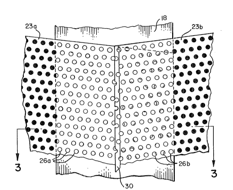
Reerriny again to FIG. 2 and also to FIG. 3, there -
is shown a lap joint of two adjacent panels 23a and 23b
with panel 23a being overlapped by 23b and both panels
riveted to the frame member 18 by rivets such as 24.
When the panels 23a and 23b are assembled on the
frame member 18 in this manner it may be seen from FIG.
2 that the overlapped edge of panel 23a shows through -
the holes 26b in the panel 23b. The surface of the
frame member 18 also shows through the holes 26a in the
panel 23a and through part of the holes in both panels
23a and 23b which happen to be in alignment with each-~
other. It may also be seen from FIG. 2 that the
15 reflected light from the reflective surfaces of the - ~ -
frame member 18 and the panel 23a which show through the
holes 26a and 26b creates a strip of greater
reflectivity in the area of the lap-joint and the frame
member 18 than in the remaining surface of the panels ~--
20 where the holes 26 are in communication with the dark -~
chamber 25. This results in a lighter strip appearing
in all the lap-joints and in front of all the frame
members 18 and the rings 19 through 22 or in any other - --~-~
area where a reflective object is in close proximity to
the back of any of the panels 23.
FIG. 6 illustrates how the light ray 27 passes ~
through the hole 26b in the panel 23b and bounces off`-~-`
the reflective surface of the panel 23a. It has been
found that even when the overlapped portion of the panel
30 23a or a frame member 18 is painted black or covered - -
-6~
~ ','. ~`''`,,
with plain black tape there is still sufficient
reflectivity from the black paint or taple that a light
strip or area will be visible on the scr~een 15.
FIGS. 4 and 5, shows an assembly similar to that
shown in FIGS. 2 and 3 except that a strip preferably of
black velour type material ~8 having vertically
extending fibers is attached to cover the reflective
surfaces of the frame member 18 and the overlapped
portion of the panel 23a. The vertically extending
fibers of the material 28 either absorb any projected
light rays or deflect them at a low angle as shown in `~
FIG. 7 where the light ray 29 passes through the hole
26b and is trapped within the hole and thereby gives the
visual impression shown in FIG. 4 where all the holes
covered by the strip of dark velour material 28 have the
same dark visual appearance as the holes 26 in
communication with the dark chamber.
Thus it can be seen that the entire visible surface --
of the screen 15 can be made to provide uniform
reflectivity by inserting the velour type material 28 to
. - . .
cover all overlapped joints and all frame members or
other objects in close proximity to the back of the
perforate screen 15.
It should be understood that the black velour type
material can be used on curved, spherical shaped or
flat projection screens to provide uniform reflectivity ~-
and eliminate light lines or other shapes on the visible ~ .
surface of the screen. . .
As a further means of preventing unwanted lines or
~0 shadows on the visible surace of the screen 15 the edge
-7-
-
, ~ ; - -.
:
~, -: . . . - .
~ 3 ~ 2 ~
30 of the overlapping panel 23b is beveled as shown in
FIGS. 3, 5, 6 and 7. The beveled edge 30 is then
painted or coated the same color as the rest of the
reflective surface of the screen 15.
These and various other modifications can be made
herein without departing from the scope of the
invention.
''' ' '';~':'
:.."~"
. . .
.. ..
.. ~.. ~,,. ~.
,.' ' -' -~ ,~
,... ,~. ;, ~.
....
. - : .: :. .: -
. .~ -, -,...
" ` `'- .~
-8- .
, .: ~: `
., ~ ~ . , . . , -
.. .. . . . .