Note: Descriptions are shown in the official language in which they were submitted.
2030371
METHOD FOR RECONDITIONG OF THE SEALING FACE
ON A DRYING CYLINDER OF A PAPER MACHINE AND
DEVICE FOR RECONDITIONING OF THE SEALING FACE
The invention concerns a method for
reconditioning of the sealing face on a drying cylinder
of a paper machine and an apparatus for reconditioning
of the sealing face.
In ageing paper machines, a problem has been
that the sealing faces of the manholes at the drying
cylinders become corroded such that it has not been
possible to guarantee good sealing by means of the
currently available sealing materials. The
reconditioning of the sealing face placed at the end of
a cylinder has proven to be particularly laborious. The
reconditioning of the manhole of the door itself is no
problem, because it can be carried easily to the machine
tool. Instead, the conditioning of the sealing face on
the roll end, to be fitted against the door, has caused
problems. Disassembly of the construction has required
a considerable amount of time and, thus, the cost of
reconditioning has become high as a paper machine
comprises a number of seal faces to be reconditioned.
The present invention is directed towards the
provision of an entirely novel device and method for
reconditioning of the sealing face of a manhole while
the drying cylinder is in its place in the paper
machine. According to the invention, a low weight
portable, apparatus is provided which is supported by
its frame on the structure of the end flange of the roll
,~ ~
2 2030371
and in which method the device comprises guides which
comply with the shaft of the manhole opening and along
which the reconditioning device is passed.
The method in accordance with the invention
for reconditioning of a sealing face in a paper machine
is mainly characterized in that in the method a separate
frame member is attached to the cylinder end, said frame
part comprising guides, and that in the method a
machining unit is displaced along the guides, said
machining unit being fitted to machine the sealing
faces.
The apparatus in accordance with the invention
for reconditioning of the sealing face is mainly
characterized in that the apparatus comprises a frame
part to be attached to the end of the cylinder, said
frame part including guides, and that the apparatus
comprises a machining unit moved along the guides, which
unit includes a motor that rotates the tool.
Accordingly, in one aspect, the present
invention provides an apparatus for reconditioning of
the sealing face of a drying cylinder of a paper machine
comprising: a frame member attachable to an end of said
drying cylinder and comprising a plurality of guide
members integral thereto; a machining unit comprising a
tool for machining said face, said machining unit being
connected to said frame member so as to be
2030371
2A
movable along said guide members for contacting said
tool with said sealing face; a drive motor having an
output shaft connected to said tool such that rotational
movement of said output shaft is transmitted to said
tool; said machining unit comprising a hollow shaft
connected to said output shaft of said motor and
displaceable in a direction perpendicular to said
sealing face; a plurality of guide sledges connected to
said hollow shaft; a plurality of rollers attached to
said guide sledges, said rollers being engaged to
respective ones of said plurality of guide members and
said engaged rollers being displaceable along said
respective guide members; and one or more locking
members for attaching said frame members to said
cylinder.
In another aspect, the present invention
provides an apparatus for reconditioning of the sealing
face of a drying cylinder of a paper machine comprising:
a frame member attachable to an end of said drying
cylinder and comprising a plurality of guide members
integral thereto; a machining unit comprising a tool
for machining said face, said machining unit being
connected to said frame member so as to be movable along
said guide members for contacting said tool with
said sealing face; and a drive motor having an output
shaft connected to said tool such that rotational
movement of said output shaft is transmitted
2030371
2B
to said tool; said machining unit further comprising a
hollow shaft connected to said output shaft of said
motor and displaceable in a direction perpendicular to
said sealing face; a plurality of guide sledges
connected to said hollow shaft, a plurality of rollers
attached to said guide sledges, said rollers being
engaged to respective ones of said plurality of guide
members and said engaged rollers being displaceable
along said respective guide members.
The invention will be described in the
following with reference to some preferred embodiments
of the invention illustrated in the Figures in the
accompanying drawings, the invention being, however, not
confined to said embodiments alone, wherein:
Figure 1 is a sectional elevational view of a
drying cylinder of a paper machine;
Figure 2 is a partially sectional view of an
apparatus in accordance with the invention as installed
at the end of the cylinder;
Figure 3 is a sectional view taken along the
line I-I in Fig. 2;
Figure 4 is a more detailed partial
illustration of the embodiment of Fig. 2; and
Figure 5 shows a second preferred embodiment
of the apparatus of the invention.
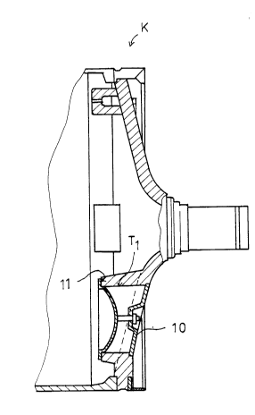
Fig. 1 shows a drying cylinder K of a paper
2030371
2C
machine. The manhole passing into the interior of the
drying cylinder K of a paper
2030371
machine is denoted with the reference numeral 10. The sealing faces
11 are fitted so that they can be reconditioned by means of the
device in accordance with the invention, which device will be
described in more detail in the following and which device is
attached to the inner faces Tl of the opening of the manhole 10.
Fig. 2 is a sectional view of a device in accordance with
the invention. The reconditioning device 12 includes a frame member
13, which is attached to the cylinder end by means of locking pins
14, preferably screws. The frame 13 includes guide members 15a and
15b of oval shape integral to the frame member.
The apparatus includes a displaceable mach;n;ng unit 16 to
be passed along the guides. The machining unit 16 comprises guide
sledges 17a and 17b, to which rollers 18a, 18b, 18c, 18d are attached
respectively to both sledge portions 17a and 17b (Fig. 3). The
rollers 18a and 18b; 18c and 18d, placed one above the other, are
fitted to be supported on the guide part 15a so that they are in
engagement with opposite sides of the guide part. In a corresponding
way, the rollers 18 are placed in engagement with the second guide
part 15b. The sledges 17a and 17b themselves are connected to the
shaft 19 of motor 23 so that the sledges can slide on the shaft in
the direction of the central axis x of the shaft 19. At its end
placed at the side of the motor 23, the shaft 19 has a threading 20
on its outer face, to which threading the nut 21 is attached, whose
end face is supported on the sledge 17a. The threading 22 of the nut
21 is compatible with the threading 20 on the shaft 19. The motor
23, preferably a pneumatic motor, is placed at the end of the shaft
19. The ~L~u~ shaft 24 of the motor 23 passes through the shaft 19,
and its end is coupled with the drive shaft 27 of the machining tool
26 by means of a belt trAn! i~sion 25. Also, the shaft 27 is
2030371
supported on the shaft 19 by means of an auxiliary frame 28.
A disk 29 is affixed permanently to the shaft 19, and a
compression spring 30 is fitted between the disk 29 and the outer
face of the sledge 17b. Thus, the position of the shaft 19 and of
the shaft 24 placed in its interior is adjustable by rotating the nut
21 in the threading 20 on the shaft 19 against the spring 30 force.
Rotation of the shaft 19 relative to the sledge 17a, 17b is prevented
by means of a key between the shaft 19 and the sledge 17b (Fig. 4).
On the contrary, the key permits movement of the shaft 19 in the
direction of the normal of the face to be machined. Thus, the
machining tool can be displaced in the direction of the normal of the
face when the machining proceeds. Fig. 2 shows the grinding disk at
the stage before machining of the face 11. By rotating the nut 21,
the grinding disk 26 can be brought into contact with the face 11 to
be machined.
The motor 23 itself is displaced manually along the guides
15a and 15b of oval shape.
Fig. 3 is a sectional view taken along the line I-I in Fig.
2. In the Figure, the guide 15a of oval shape is seen, along which
the equipment is displaced manually. From the Figure it is seen
further that the shaft 24 which rotates the tool runs inside the
shaft 19.
Fig. 4 is a more detailed partial illustration of an
embodiment of the invention similar to that shown in Fig. 2. The
motor 23 is not shown in the illustration in part. From the shaft 24
the movement of rotation is transferred to the belt pulley 31 and
from the belt pulley 31, by the intermediate of the belt 32, to the
driven belt pulley 33, which is adapted to rotate the shaft 27 of the
grinding disk 26. As is shown in the Figure, the shaft 27 of the
2030371
grinding disk 26 is mounted on an auxiliary frame 28 by bearing means
34. The shaft 19 is fixed to the sledges 17a and 17b so that
rotation between the parts is prevented by means of the key 35.
Fig. 5 shows a second embodiment of the device in accordance
with the invention, in which the motor 23 is fitted to rotate the
drive shaft 24 fitted inside the shaft 19, the grinding disk 26,
preferably a cup wheel, being connected directly to said shaft 24.
The cup wheel 256 is in a position from which it is fed into contact
with the face 11 to be machined by rotating the nut 21.
Although preferred embodiments of the subject invention have
been shown herein, it is submitted that numerous other embodiments
within the scope of the appended claims will readily occur to those
skilled in the art.