Note: Descriptions are shown in the official language in which they were submitted.
2~3~8
METHOD AND APPARATUS FOR REMOVING BINDER FROM AROUND
TELECOMMUNICATIONS CABLE CORE
This invention relates to a method and
apparatus for removing binder from around a
telecommunications cable core.
Conventionally, telecommunications cables are
constructed of multiple pairs of individually insulated
conductors grouped together to form a cable core, which
may then be surrounded by a protective sheath. During
manufacture of a cable, a spirally applied binder tape or
filament may be wound around conductors of the core, for
the purpose of holding together the conductors along the
length of the cable core, before application of
surrounding material such as a core wrap, a protective
sheath and a cable jacket. Binder tapes or filaments may
also be used to separate and identify, by binder colour,
each of a number of groups of conductors forming separate
core units which are assembled together to form the cable
core of a large diameter multiconductor cable.
Testing of cable cores following their
manufacture may reveal defective conductors. If it is
required to remove and replace a defective conductor pair
with a new conductor pair, or to reuse (recycle) good
conductors, the binder tape must first be removed before
the conductors can be separated from the group. The
binder tape is removed manually by cutting and unwinding
the binder, and this task is labor intensive and time
consuming.
The present invention seeks to provide an
apparatus for unwinding binder from a telecommunications
cable core.
According to one aspect of the present
invention, an apparatus for removing spirally wrapped
binder from around a telecommunications cable core is
provided comprising:- drive means disposed at a location
along a passline for cable core, the drive means for
rotating around the passline a take-up reel for binder
when the take-up reel is disposed in a take-up reel
station; binder unwinding and guide means which is
~3~
freely rotatable about the passline and is operable for
guiding binder to the take-up reel station from a cable
core moving along the passline so that during operation
of the drive means with a take-up reel in the take-up
reel station binder is taken up around the take-up reel,
the unwinding and guide means being rotatable under
binder tension to cause unwinding of the binder from the
core; and the apparatus also comprising means to control
the speeds of rotation of the take-up reel when driven by
the drive means and of the unwinding and guide means
relative to the cable core speed along the passline so
that the binder is in tension during take-up of binder
and is controllably unwound from the cable core.-
The apparatus according to the invention as
defined above is capable of controllably removing binderfrom a cable core thereby reducing the time required
compared with manual removal of binder while also
avoiding intensive manual labor.
In a preferred arrangement, the binder
unwinding and guide means comprises a guide element
freely pivotally mounted about an axis so as to be
pivoted dependent on the angle of the binder as it leaves
the cable cor~, the guide element operably connected to
the control means to cause operation of the control means
at a certain pivotal position of the guide element
corresponding to a limiting position of the binder
upstream as it leaves the cable core.
The guide element allows for a simple and
easily constructed operational design for causing
operation of the control means.
In other arrangements, operation of the control
means is controlled by devices other than the guide
element. In these arrangements, operation of the control
means is caused by a limit sensor for detecting the
position at which binder leaves the core or by a sensor
for measuring the binder speed, the sensor being operably
connected to the control means for operating the control
2~3a~
means when the sensor detects binder parameters beyond
predetermined limits.
According to a further aspect of the invention,
there is provided a method of removing binder from around
a telecommunications cable core, the method comprising:-
controllably passing the cable core along a passline and
through a binder take-up reel being rotatably driven
around the cable core and, during movement of the cable
core along its passline and during rotation of the reel,
passing the binder through a binder guide means which is
freely rotatable around the passline and around the
binder take-up reel, the binder moving from the binder
guide means and being wound around the rotating take-up
reel, tension in the binder applying a torque to cause
rotation of binder guide means around the passline to
enable the binder to be unwound from the core; and
controlling the speed of rotation of the binder guide
means and the speed of rotation of the take-up reel
relative to the cable core speed along the passline so
that the binder is in tension during take-up of the
binder and is controllably unwound from the cable core.
Embodiments of the invention will now be
described by way of example, with reference to the
accompanying drawings, in which:-
Figure 1 is an isometric stepped sectional view
of a telecommunications cable;
Figure 2 is a block diagram of an assembly of a
cable core unreeler, an apparatus for removing binder
from a telecommunications cable core according to the
embodiment, and a cable core reeler;
Figure 3 is a cross-sectional view of the
apparatus for removing binder from a telecommunications
cable core according to the embodiment, showing a cable
core along the passline;
Figure 4 is a view of the apparatus in the
direction of arrow IV in Figure 3, a cable core being
shown in section;
203~8
Figure 5 is an enlarged cross-sectional view of
a limit sensor and switch assembly of the binder
unwinding and guide means; and
Figure 6 is an isometric cut-away sectional
view of the limit sensor and switch assembly.
A telecommunications cable 10, as shown in
Figure 1, has a conventionally constructed core 16 of
multiple pairs of twisted together individually insulated
conductors 12 grouped together by stranding and bound
with a spirally bound binder tape 14. Twisting and
stranding of the conductors are not shown in Figure 1, to
simplify the drawing. A protective sheath 18 and a
jacket 19 are applied over the cable core 16 to provide
the finished cable 10.
An apparatus 20 for removing binder from a
telecommunications core according to the embodiment is
shown in Figures 2 to 5. The apparatus 20 forms part of
an in-line assembly comprising a cable core unreeler 22,
the apparatus 20, and a cable core reeler 24 (Figure 2).
The cable core unreeler 22, from which the bound cable
core is supplied to the apparatus 20, and the reeler 24,
which takes up unbound cable core, are conventional and
will not be described further. The assembly 21 provides
a passline 30 for cable core 16 from the cable core
unreeler 22, through guide rollers 32, through the
apparatus 20, and through further guide rollers 34 to the
cable reeler 24.
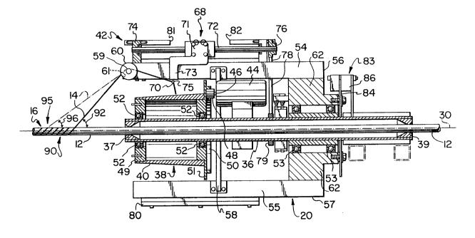
The apparatus 20, shown in cross-sectional view
along the passline 30 in Figure 3, comprises a center
cylindrical guide shaft 36 surrounding the passline 30
for cable core 16, a binder take-up reel station 38 and
binder unwinding and guide means 42. The ends 37 and 39
of the cylindrical shaft 36 are shaped to prevent the
cable core 16 from wandering sideways as it moves through
the guide shaft 36. The shaft 36 forms a common mounting
for the unwinding and guide means 42 and for a drive
means and control means to be described.
2 0 ~
A take-up reel 40 is permanently mounted in the
take-up reel station 38. The take-up reel 40 is
concentrically mounted upon the shaft 36 by bearings 52
held within ends 49 and 51 of the reel. One end 51 of
the reel extends outwardly beyond the reel diameter to
provide an internally geared axial flange 50. The take-
up reel is tapered towards an upstream open end 49 as
shown in Figure 3 for a reason to be described. Drive
means are provided for rotating the take-up reel 40
around the passline 30. The drive means comprises an
electric motor 44 having a driving gear 48 mounted upon
its drive shaft 46, the driving gear 48 engaging the
geared flange 50 of the take-up reel 40.
The binder unwinding and guide means 42
comprises a binder guide element 60 mounted on an
upstream end of a support member 54, which is an axially
extending arm in a position spaced radially outside the
take-up reel 40 mounted in the take-up reel station 38.
The unwinding and guide means 42 also includes a second
binder guide element 70 provided as part of a traverse
mechanism 68. The guide elements 60 and 70 and the
traverse mechanism are discussed in detail below. The
support member 54 is secured at one end 56 to a
downstream end plate 62 freely rotatably mounted on the
shaft 36 on bearings 53. A second support member 55,
which is also an axially extending arm, diametrically
opposed to support member 54 and carrying a counterweight
80, is also secured at one end 57 to the end plate 62 so
as to provide for balanced rotation of the unwinding and
guide means 42 around the guide shaft 36 at a desired
operating speed. An annular bracing member 58 extends
between the support members 54 and 55 around the take-up
reel station. The unwinding and guide means 42 is
operable, when cable core 16 is moving along the passline
30, for guiding binder 14 from the core 16, by way of the
guide elements 60 and 70, to the take-up reel station 38
so that binder 14 is taken up around the take-up reel 40
during operation of the motor 44 and the binder unwinding
2~3Q~
and guide means 42 is rotatable under binder tension so
as to unwind binder from the core 16 as will be described
below.
The binder unwinding and guide means 42
includes a winding traverse mechanism 68 for controlling
the winding of binder 14 onto the take-up reel 40. The
winding travarse mechanism 68 has a movable element 71
which is axially traversable along a drive shaft 72. The
binder guide element 70 is a flange, having a guiding eye
75 formed in it, provided in the free end of an arm 73 of
the movable element 71 of the traverse mechanism 68. The
traverse mechanism 68 also comprises a drive wheel in the
form of gear 76 for the shaft 72. An endless flexible
drive member 78 drivably passes around the gear 76 and
around a non-rotatable wheel in the form of a gear 79
mounted concentrically around the guide shaft 36. The
drive shaft 72 is rotatable by the endless flexible drive
member 78 upon rotation of the binder unwinding and guide
means 42 around the guide shaft 36. On rotation of the
drive shaft 72, the moveable element 71 is caused to move
alternately to and fro along the shaft 72 between end
stops 81 and 82 so that the guide element 70 causes
binder to traverse from end to end of the take-up reel 40
as it is wound around the reel.
The binder guide element 60 of the binder
unwinding and guide means 42 has an eye 61 through which
binder passes as it unwinds from the cable core 16 (see
particularly Figure 4). The angle 92 (Figure 3) at which
binder diverges from the cable core and approaches the
guide element 60 is determined by the position along the
passline at which binder detaches from the cable core.
The guide element 60 is freely pivotally mounted on a
shaft 59 rotatable about an axis so that as the binder
passes through the eye 61 and around the shaft 59, the
guide element 60 is pivoted dependent on the angle g2 of
binder 14 as it leaves the cable core 16. Since the
angle 92 at which the binder 14 leaves.the cable core 16
is dependent on position along the passline of the point
of detachment 90 of the binder 1~ from the cable core,
the angular position of the eye 61 relative to the axis
of the shaft 59 is dependent on the point of detachment
90. The rotatable shaft 59 has a trigger pin 89
extending through it and projecting radially from one
side of the shaft 59. The trigger pin 89 forms part of
an automatically operat~d switch means 94 of a control
means now to control the speeds of rotation of the take-
up reel 40 and of the binder unwinding and guide means 42
relative to the cable core speed-along the passline 30.
The control means will be described below. The trigger
pin 89 is rotatable with the shaft 59 towards and away
from a switch operating position, so that the guide
element 60 is operably connected to the control means so
as to cause operation of the control means at a certain
pivotal position of the guide eye 61 on the guide element
60 which corresponds to a limiting position of the binder
upstream as it leaves the cable core.
The means to control the speeds of rotation of
the take-up reel 40 and of the binder unwinding and guide
means 42 operates so that the binder 14 is in tension
during take-up onto the reel 40, and so that the point of
detachment 90 of the binder 14 from the cable core 16 is
controllably maintained within limited range of positions
along the passline 30, between the guide rollers 32 and
the end 37 of the guide shaft 36.
The control means comprises a brake mechanism
83 to control the speed of rotation of the unwinding and
guide means 42 and the automatically operated switch
means 94 to operate the brake mechanism 83 so as to stop
or slow down rotation of the binder unwinding and guide
means 42 and interrupt the unwinding of the binder,
should the point of detachment of the binder from the
cable core move upstream beyond a preset limiting
location. With this object in mind, the automatically
operated switch means 94 includes a limit sensor 88 which
comprises the trigger pin 89 and a sensor element 87 so
as to form a switch means of the type known as an
~3~
inductive proximity sensor switch (F.igures 5 and 6). The
trigger pin 89 for operating the switch, being mounted on
the freely rotatable shaft 59 of the binder guide element
60, is movable by pivoting movement of the shaft 59
towards and away from the sensor element 87 of the switch
to cause operation of the switch. Thus the switch means
94 responds to changes in the angle of approach of the
binder 14 to the binder unwinding and guide means 42 as
governed by the position of the trigger pin 89 rotatable
lo with the guide element 60 (Figure 6). Signal from the
sensor element 87 of the switch is transmitted through a
slip ring arrangement to a control module which actuates
the brake mechanism 83.
The brake mechanism 83 comprises a brake disc
84 secured to the end plate 62 and thus rotatable with
the support member 54 about the passline, and brake
callipers 86, secured to the guide shaft 36, for engaging
the brake disc 84.
In use of the apparatus, the stranded together
conductors 12 of the cable core 16 are directed through
the guide shaft 36 and as the conductors of the cable
core 16 move together along the passline 30, the binder
14 is caused to diverge from the conductors 12 and to
move through the binder guide elements 60 and 70 on the
binder unwinding and guide means 42 and to be guided onto
the binder take-up reel 40 so that the binder is taken up
around the binder take-up reel 40 as the reel rotates
during operation of the drive means 44. As the binder 14
moves from the binder guide elements 60 and 70 and is
wound around the take-up reel 40, tension in the binder
14 as it is wound onto the take-up reel applies
sufficient torque to the binder guide means 60 to cause
rotation of the binder unwinding and guide means 42
around the passline so as to unwind binder 14 from the
cable core 16 as it moves along the passline 30.
Rotation of the binder unwinding and guide means 42
around the guide shaft 36 also drives the operation of
the traverse mechanism and movement of the guide element
2Q3~8
70 on the traverse mechanism controls winding of the
hinder onto the take-up reel.
In theory, since the cable core 16 is moved
along the passline 30 through the apparatus at a fixed
speed, if the length of binder per unit length of cable
core is known, the binder may be unwound at an
appropriate and constant rate so that the position 90
along the passline 30 at which binder detaches from the
cable core 16 as it unwinds remains stationary. Thus,
the unwinding of the binder may be controlled simply by
regulation of the speed of rotation of the take-up reel
40 relative to the cable core speed along the passline so
that binder is unwound at a desired rate. However, this
theoretical ideal is not achieved in practice.
In practice, it is desirable to be able to
control the unwinding of the binder 14 by a simple and
economical mechanical means. This is effected by regula-
tion of the speeds of rotation of the take-up reel 40 and
of the binder unwinding and guide means 42 relative to
the cable core 16 speed along the passline 30. The
binder unwinding speed can then more easily be regulated
to accommodate cable cores having binder wound with
different pitches.
In order to prevent bound cable core from
advancing into the guide shaft, the rate at which binder
is unwound per unit linear length of cable core is
controlled by the speed of the motor 44 so as to be
slightly greater than that required merely to keep pace
with the rate at which cable core moves along the
passline. Thus, the point 90 at which the binder 14
detaches from the surface of the cable core 12 tends to
advance upstream from the guide shaft so that the angle
between the passline 30 and the binder 14 decreases as
binder is unwound from the core 12. When the point of
detachment 90 of the binder from the cable core reaches a
preset upstream limit 95 (as shown by the chain-dotted
outline of binder tape 14 in Figures 3 and 6), as causing
rotation of the trigger pin 89 of the limit sensor 88
~3~98
into the switch operating position, the switch means 94
operates the brake mechanism 83 causing the brake to slow
down rotation of the unwinding and guide means 42. The
tension in the binder may then increase causing the motor
44 to slow down with resultant slowing down of the take-
up reel 40. While the brake is applied, the cable core
12 continues to advance along the passline 30 so that the
point of detachment 90 of the binder from the core will
move downstream and bring the angle of approach of the
binder within operating limits so that the trigger pin 89
rotates away from the switch operating position, causing
the switch means 94 to release the brake mechanism 83.
The control means guards against unwinding the
binder too quickly relative to the cable core speed, when
the point of detachment of the binder will move upstream
away from the guide shaft, which may lead to jamming or
breakdown of the apparatus.
The apparatus of the embodiment operates using
only one drive motor 44 and simple control means. A
separate drive motor is not required on the binder
unwinding means 42, it is driven solely by binder
tension. The traverse mechanism 68 is also driven by
rotation of the binder unwinding and guide means 42,
which drives the endless flexible member 78, and thereby
operates the drive shaft of the traverse mechanism,
whereby the traverse mechanism does not require a
separate drive motor. The take-up reel 40, binder
unwinding and guide means 42 and control means of the
apparatus are mounted on the single central guide shaft
36 to simplify construction of the apparatus. The
apparatus is therefore of economical and simple
mechanical construction and requires only limited control
means or electronics.
The open end and tapered shape of the take-up
reel allows binder to be easily removed from the take-up
reel by pulling binder off the open end of the reel,
avoiding the necessity for unwinding from the take-up
reel binder which is to be discarded. It is therefore
~3~
ll
unnecessary for the take-up reel to be detachable from
the apparatus. The winding diameter of the reel must be
sufficiently large relative to the cable core diameter so
that as binder is tensioned and wound onto the take-up
reel, sufficient torque to the binder unwinding and guide
means 42 is provided by tension in the binder to cause
rotation of the binder unwinding and guide means 42.
Thi.s may be seen readily from Figure 4.
In a modification of the apparatus of the
embodiment (not shown), the drive means comprises a drive
motor 44 including a clutch mechanism which operates at a
limiting tension of the binder to prevent binder tension
increasing to the point of breakage of the binder and to
prevent unnecessary strain on the motor.
Another modification of the apparatus of the
embodiment comprises a take-up reel spindle provided
around the guide shaft for rotatably mounting a removable
take-up reel in the take-up reel station, so that the
binder unwound from a cable core may be removed on the
take-up reel.
Although the embodiment shown uses only a
simple mechanical control means for regulating the
unwinding of binder, control means for activating the
brake mechanism may use alternative mechanical or
computer assisted means and in further modifications of
the apparatus alternative types of limit sensor may be
used. In other arrangements of the apparatus, operation
of the control means is controlled by devices other than
the guide element 60. In these arrangements (not shown),
operation of the control means is caused by a limit
sensor for detecting the position at which binder leaves
the core or by a limit sensor for measuring the binder
speed, the sensor being operably connected to the control
means for operating the control means when the sensor
detects binder parameters beyond predetermined limits.
In further modifications, an alternative drive
means comprises a variable speed motor for rotating the
take-up reel and a limit sensor using electronically
2~3~98
computer assisted means to control the speed of the drive
means. The binder unwinding speed may then be
continuously matched to the cable core speed to prevent
both unwinding of binder too quickly, when the point of
detachment will move upstream away from the guide shaft
and unwinding of the binder too slowly, when bound cable
core will advance downstream into the end 35 of the guide
shaft 36, either situation which may lead to breakdown of
the apparatus.
lo In addition an alternative brake means
comprises a brake operable, for example, directly on the
support member 54 of the unwinding and guide means
instead of directly onto the end plate 62.