Note: Descriptions are shown in the official language in which they were submitted.
2 ~1 3 ~
TITL~ QF ~E INYENTl~N
Reaction Vessel
BACKGRO~ND OF THE INVENTION
This invention relates to a reaction vessel which may be
used for measuring a minute amount of substance present in a
living body by a simple and convenient operation.
Microanalysis of a biological substance is often carried
out for the purpose of diagnosing various diseases and
determining effects of various treatments. A number of
assays have been developed one after another ranging :Erom
simple and convenien-t assays to highly sensitive assays
realizing a high measurement accuracy. Among these,
simplified assays, which require no measuring equipment or
reaction system, are finding a wide application owing~to
:
their simpIe operation in such cases wherein qualitative or
semi-quantitative measurements are just sufficient to make
diagnoses. For~example, simplified assays are used for a
~measurement of glucose in urine and other biochemical tests,
as ~el;l as;pregnancy tests. Recently, simplified assays have
lso;~been~used for detection of various pathogenic viruses by
nucleic~acid hybrldi2ation with DNA probes.
Typical simplifled assays based on immunoreactions
~(antigen-antibody reactions) include those utilizing an
agglutination reaction ~ .e. agglutinatlon or non-
agglutination~ using a latex or red blood~cell for their
::
2~3 lL~
carrier and enzyme immunoassays (EI~) using an enzyme for
labelling purposes.
Among the agglutination reactions, those utilizing
agglutination-precipitation reaction are conducted in an
ampoule having a spherical bottom surface by using red blood
cell or analogous synthetic material for their carrier, and
their results are evaluated by presence or size of a ring or
a spot precipitated inside the spherical bottom surface.
These processes may be conveniently carried out with a
relatively high measurement sensitivity, but may take a long
time for obtaining the results since they are based on
precipitation of red blood cells or analogous synthetic
materials.
The process utilizing a latex for the agglutination
reaction is carried out on a slide by using a latex as their
carrier. The results are evaluated after stirring the sample
by observing the degree of agglutination. The latex
agglutination reaction is not very sensitive, but can be
carried out in a short period by a simple operation.
Therefore, the latex agglutination reaction is widely
employed in such application as pregnancy test wherein a high
sensitivity is not necessarily required. The latex
agglutination reaction, however, requires much skill for
determination of the results, and therefore, those who are
capable of making an accurate determination are primarily
limited to doctors and laboratory technicians in medical
institutions including hospitals and cIinics.
~3~
--3--
The enzyme immunoassays are more sensitive than other
simplified assays, but often take a relatively long reaction
time for obtaining a high sensitivity. The enzyme
immunoassays also suffer from a drawback that troublesome
operations are required for B/F (bound/free) separation and
an incomplete B/F separation would result in non-specific
reactions in the subsequent enzyme reaction step leading to
an erroneous evaluation of the results. B/F separation is a
separation of an antigen-antibody complex (an antigen bound
to an antibody, B) frorn free antigens or antibodi.es (F) in
the case of an antigen-antibody reaction.
As set forth above, the simplified assays based on
agglutination reactions are capable of detecting the presence
of a substance, but are unsuitable for quantitative analyses
wherein the amount of the substance present is to be
:
determined. On the other hand, the enzyme immunoassays, in
spite of their drawbacks of a prolonged reaction time and a
troublesome B/F separation, are capabIe of conducting a
quantitative assay as well as a qualitative assay since the
results of the enzyme immunoassays may be represented in
qualitative or quantitative forms by either the
presence/~absence or the degree of;color change, namely, co].or
development of the reaction solution. Also, the resul-ts may
;be easily and accurately discerned by~anyone. Owing to such
an advantage, a nurnber of investigations have been carried
out to~shorten their reaction time and to simplify the B/F
'
, ~
2~3~Q~
separation. As a matter of fact, an enzyme immunoassay
satisfactory for practical use is not yet developed.
Recently, an assay utilizing a nucleic acid
hybridization is employed for the simplified assay to detect
a particular DNA or RNA (only DNA may be hereinafter
mentioned, but detection of an RNA is also intended to be
included within the scope of the invention). The nucleic
acid-hybridization assay is analogous to the immunoassay
utilizing an antigen-antibody reaction, especially an enzyme
immunoassay, in that the reaction mechanism is based on
selectivity of the DNA probe to hybridize with the
particular DNA. Accordingly, steps included in enzyme
immunoassays are likewise required in the nucleic acid-
hybridization assay, and conventional nucleic acid-
hybridization assays also suffered from the drawbacks of a
long reaction time and a troublesome B/F separation, which
should be overcome.
To overcome such drawbacks, Japanese Patent Application
Kokai No. 63-20063 and Japanese Patent Application 62-215992
propose reaction vessels having a dish-like configuration.
~ By using the dish-like reaction vessels of these patent
~applications, qualitative enzyme immunoassays may be carried
out by a~significantly simplified procedure. These reaction
vessels, however, are still insufficient to make the best of
the advantage of the erzyme immunoassays that they may be
used for quantitative assays.
2~3~
--5--
The enzyme imm~noassay involves a plurality of steps
including, for example, sample dispensing and addition of
washing solution, solution of an enzyme-labelled antibody,
chromogenic reagent and enzyme substrate. Accordingly, this
assay is quite complicated and requires a prolonged period
before an evaluation can be made. These drawbacks are yet to
be overcome.
For simplifying such an assay capable of conducting a
quantitative evaluation, it would be essential to simplify
the steps of B/F separation and addition of sample and
various reagents. In such respects, the above-mentioned
dish-like reaction vessels are yet to be improved.
S~MMARY OF THE INVFNTION
As set forth above, a highly sensitive simplified assay
which may realize an accurate measurement by a convenient
operation is not yet developed.
The reaction vessel of the present invention is
developed in view of such a situation in the art.
Accordingly, it is an object of the present invention to
provide a reaction vessel which is capable of conducting a
highly~sensit~ive assay with an accurate and simple B/F
separation by simple sample and reagent adding operations.
~ Another object of the present invention is to provide a
reaction vessel of a wide application including such an assay
as enzyme immunoassays and assays using nucleic acid
hybridization.
~ . .
2~3~ 0~
A further object of the present invention is to provide
a reaction vessel which is capable of assaying multiple items
at a time by a simple operation.
Accordingly, this invention is directed to a reaction
vessel adapted for enzyme immunoassays and nucleic acid-
hybridization assays which is capable of continuously
carrying out a series of steps including antigen-antibody or
hybridization reaction, B/F separation, enzymatic reaction,
and evaluation of the results in a relatively short period.
The reaction vessel of the instant invention is capable
of carrying out ordinary assays without any additional
apparatus. However, the reaction vessel may be combined with
other automatic measuring apparatus for -the purpose of
continuously treating a number of samples or enabling a
quantitative evaluation.
~ ~ccordingly, the present invention, which fulfills the
above-described requirements, comprises a reaction vessel
comprising a body structure having provided therein at least
one reaction unit comprising a channel having at least one
fluid inlet and at least one reagent-immobilized area in the
downstream of all of the at least one fluid inlet. The
channel is provided with a vent mechanism, and the reagent-
immobilized area~has a reagent fixedly immobilized there-to.
.
BRIE~ DESCRIPTION OF THE DR~WINGS
~; ~ FIG. la is a perspective view of a reaction vessel
according to an embodiment of the present invention, and
~3~
FIG. lb is a cross-sectional view of the reaction vessel
of FIG. la taken alonq a channel thereof.
FIG. 2a is a perspective view of a reaction vessel
according to another embodiment of the present invention, and
FIGS. 2b and 2c are cross-sectional vie~s of the
reaction vessel of FIG. 2a taken along lines A-A and B-B,
respectively.
FIGS. 3a, 3b and 3c are top plan views of segments of a
reaction vessel according to a further embodiment of the
present invention,
FIG. 3d is a side view of the reaction vessel co~prising
the segments of FIGS. 3a, 3b and 3c assembled together, and
FIGS. 3e and 3f are cross-sectional views of the
reaction vessel of FIG. 3d taken along~lines C-C and D-D,
respectively. ~ ~ ~
FIG. 4 is a perspective view of a reaction vessel
according to a still further embodiment of the present
invention.
: `
; ~ FIG. 5 1s a top plan view of a reaction vessel according
to a still further embodiment of the present invention.
FIGS. 6a and 6b are top plan views of;segments of a
.reaction vessel according to a still further embodiment of
the present invention, and
FIG. 6c~;1s a slde view o~ the reaction vessel comprising
~ the~segments of FIGS. 6a and 6b assembled together.
:: ~ : : : :
:: : ::
.:` '
. .
.
: : .
;' ~ , ' :
~'
.
.
2 ~
FIGS. 7a and 7b are top plan views of segments of a
reaction vessel according to a still further embodiment of
the present invention, and
FIGS. 7c and 7d are side views of the reaction vessel
comprising the segments of FIGS. 6a and 6b assembled
together.
FIGS. 8a, 8b and 8c are top plan views of segments of a
reaction vessel according to a still further embodiment of
the present invention,
FIG. 8d is a side view of the reaction vessel comprising
the segments of FIGS. 8a, 8b and 8c assembled together, and
FIG. 8e is an enlarged cross-sectional view of the
reaction vessel of FIG. 8d at part A of FIG. 8b.
FIGS. 9a and 9b are top plan views of segments of a
reaction vessel according to a still further embodiment of
the present~invention.
FIG. 9c is a side view of the reaction vessel of FIGS.
9a and 9b taken along lines X-X.
FIG. 10 is a top plan view of a reaction vessel
according to a still further embodiment of the present
invention. ~ ~
: :
FIG. l~l is a top plan view of a reaction vessel
according to~a still further embodiment of~the present
invention
; FIG. 12 is a top plan view of a reaction vessel
according to a still further embodiment of the present
inventio~.
,; '
~3~
--9--
FIGS. 13a, 13b and 13c are fragmental top plan views of
reaction vessels showing channels according to differen-t
embodiments of the present invention.
FIGS. 14a, 19b, 14c, 14d, 14e and 14f are fragmental
cross-sectional views of reaction vessels showing channels
according to different embodiments of the present invention.
FIG. 15 is a partial cr~ss-sectional view of a reaction
vessel according to an embodiment of the present invention
illustrating a process for fabricating a channel.
FIG. 16a is an exploded perspective view of a reaction
vessel according to an embodiment of the present invention
illustrating a process for fabricating a channel, and
FIG. 16b is a partial cross sectional view of the
reaction vessel depicted in FIG. 16a taken across a channel
thereof.
; ~ FIGS. 17a, 17b and 17c are schematic top plan views of
reagent-immobilized zones according to different embodiments~
of the present invention wherein a plurality of reagent-
immobilized areas are arranged in different patterns.
FIGS. 18a, 18b and 18c are partial schematic cross-
sectional views of reaction vessels according to different
embodiments of the invention taken across a channel at a
reagent-i~mobilized area, wherein said reagent-immobilized
area comprises a recess provided in the channel, a group of
.
protrusions in the channel, and a group of protrusions
provided within a recess in the channel, respectively.
:
, . - ,~ .
2 ~ 3 ~
-10-
FIGS. l9a, l9b and l9c are schematic views of groups of
protrusions according different embodiments of the present
invention.
FIG. 20 is a partial top plan view of a reaction vessel
according to a still further embodiment of the present
invention.
FIG. 21 is a partial top plan view of a reaction vessel
according to a still further embodiment of the present
invention.
~E~aL~ED D~CRIPTI~N OF ~ F~ N
The present invention is hereinafter described in
detail.
The reaction vessel of the present invention comprises
at least one reaction unit. A reaction vessel with one
reaction unit is first described by referring to drawings
although a wide variety of embodiments are included within
the scope of the invention.
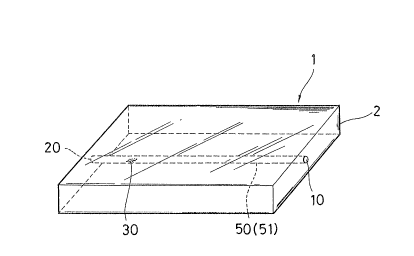
FIG. la is a perspective view of a reaction vessel
according to an embodiment of the present invention, and FIG.
lb is a cross-sectional view of the reaction vessel of ~IG.
la taken along a channel thereof.
FIG. 2a is a perspective view of a reaction vessel
,:
according to another embodiment of the present invention, and
~ A
FIGS. 2b and 2c are cross-sectional views~ of the reaction
; vessel of FIG. 2a taken along lines A-A and B-B,
respectively.
,. ~f; . ~ .,
2 ~ 3 ~
FIGS. 3a, 3b and 3c are top plan views of segments of a
reaction vessel according to a further embodlment of the
present invention, FIG. 3d is a side view of the reaction
vessel comprising the segments of FIGS. 3a, 3b and 3c
assembled together, and FIGS. 3e and 3f are cross-sectional
views of the reaction vessel of FIG. 3d taken along lines C-C
and D-D, respectively.
FIG. 4 is a perspective view of a reaction vessel
according to a still further embodiment of the present
invention.
FIG. 5 is a top plan view of a reaction vessel according
to a still further embodimen-t of the present invention.
FIGS. 6a and 6b are top plan views of segments of a
reaction vessel according to a still further embodiment of
the present invention, and FIG. 6c is a side view of the
reaction vessel comprising the segments of FIGS. 6a and 6b
assembled together.
FIGS. 7a and 7b are top plan views of segments of a
reaction vessel according to a still further embodiment of
the present invention, and FIGS. 7c and 7d are side views of
the~reaction vessel comprising the~segments of FIGS. 6a and
6b assembled together.
FIGS. 8a, 8b and 8c are top plan views of segments of a
reaction vessel according to a still further embodiment of
the present invention, FIG. 8d is a slde view of the reaction
vessel comprising the segments of FIGS. 8a, 8b and 8c
assembled together, and FIG. 8e is an enlarged cross-
. . , ':
, '
~3~
-12-
sectional view of the reaction vessel of FIG. 8d at part A of
FIG. 8b.
FIGS. 9a and 9b are top pian views of segments of a
reaction vessel according to a still further embodiment of
the present invention. FIG. 9c is a side view of -the reaction
vessel of FIGS. 9a and 9b taken along lines X-X.
FIGS. 10, 11 and 12 are top plan views of reaction
vessels according to still further embodiments of the present
invention.
The reaction unit of the present reaction vessel
essentially comprises a body structure, a channel provided in
the structure having at leas-t one fluid inlet and at least
one reagent-immobilized area in the channel in the downstream
of all of the at least one fluid inlet. The channel has a
vent mechanism, and the reagent-immobilized area has a
reagent fixedly immobilized thereto.
Structure 2 may comprise one member as shown in FIG. la,
two segments 4 and 5 as shown in FIGS. 2a and 4, three
segments 3, 4 and 5 as shown in FIGS. 3d, 3e and 3f, or four
or more segments.
Structure 2 may also comprise segments 4 and 5 and a
pai~r of supports 9a as shown in FIG. 6cl~ segment 4 having a
curved lower major surface and sheet-like segment 8 covering
the upper major surface of segment 4 serving a lid for the
channel as shown in FIG. 7c, or segments 3, 4 and 5 and plate
9b as shown in FIG. 8d.
~ ::
~ ~ 3 ~
The structure may preferably comprise at least two
segments with the channel being provided in at least one of
the channel for ease of providing the reagent-immobilized
area and a reagent-attached area in the channel as will be
described later. Alternatively, the structure may comprise a
segment having the channel in an open state and a sheet-like
lid covering the upper major surface of the segment with
required parts of the channel being left open.
Structure 2 may also have a structure as shown in FIGS.
6c, 7c and 8d so that the reaction vèssel will be inclined in
the direction indicated by an arrow in each figure at the
time of substantial completion of the reaction to indicate
that the reaction has been substantially completed and the
results are ready to be qualitatively or quantitatively
evaluated.
The structure may comprise such materials as glass or
plastic resins such as epoxy resins, polyacrylic resins,
polyester resins, polystyrene resins and polyvinyl chloride
resins. The material is either hydrophilic in itself or can
be made hydrophilic by, for example, providing a frosted
finish. ~.
The uppermost segrnent of the structure 2 may be a sheet-
like lid. This lid segment may comprise various materials as
enumerated above for the structure 2, but may also comprise a
metal such as aluminum. The sheet like segmen-t may be bonded
to other part of the structure 2 by heat-seal or with an
2~a~
-~14-
adhesive layer disposed on one surface of the sheet-like
segrnent.
Color of the structure is not particularly limited.
When the results of the reaction are indicated by a color
change, the structure may preferably be either -totally
transparent or comprise a transparent upper segment and white
lower segment. When the results of the reaction are
indicated by fluorescence, the structure may preferably be
transparent.
The channel is provided in at least one segment of the
structure. Vari.ous liquids such as samples, for example,
urine and serum, washing solutions and reaction solutions as
well as air passes through the channel. The channel has at
least one fluid inlet. The channel is also in comrnunication
with a vent mechanism such as a ventilatory outlet.
The channel may have only one fluid inlet 10 as shown in
FIGS. la, 2a, ~, 5,~ 6b, 8a, 9a, 10 and 12. The channel may
also have two or more inlets 10 and 11 as shown in FIGS. 3a
and 3b, and 7a.
When the channel is provided with a plurality of fluid
in;.Lets, a plurality;of different liquids, for example, a
sample and a react;on solution may be introduced~into the
fluid inlets either simultaneously or one after another in a
predetermined~order.
When the channel is provided with a~plurality of~fluid
inlets, it is preferred to arrange fluid inlets 10 and 11
such that the fluid entering from the fluid inlet in the
~3~
-15-
downstream will flow in substantially the same direction as
the fluid entering from the most upstream fluid inlet as
shown in, for example, FIGS. 3a through 3f.
Although the most upstream fluid inlet is provided in
the upstream end of the channel in most cases, it is also
possible to provide fluid inlet 10 in the midst of channel 50
as shown in FIG. 9b. However, in the embodiment of FIG. 9b,
the fluid initially flowing upstream ~'toward right in FIG.
9b) will finally flow downstream.
The vent mechanism is typically a fluid outlet provided
in the channel having a construction capable of ventilation.
Referring to FIGS. la, 2a, ~, 5 and 10, fluid outlet 20
comprises a downstream open end of the channel situated in
the side surface of the structure. Referring to FIG. 3c, the
channel is bent in its downstream end portion to form fluid
outlet 20 opening at the lower major surface of the
structure. In these cases, liquids including the sample and
the reagents as well as gases such as air are discharged from
fluid outlet 20.
Referring to FIGS. 6a, 6b, 7a, 7b and 8a, the channel is
provided with two fluid outlets 20 and 21.~ The outlets may
be s~ituated in upper, side or lower surface of the structure.
~: : :
In these embodiments, as shown in top plan views of segments
of FIGS. 6a, 6b, 7a, 7b, 8a and 8b, the channel is provlded
with fluid sump 90 and water-absorbent material 81 is
accommodated in fluid sump 90 as will be described later. In
such a case, the liquid within the channel rarely flows out
-16-
of fluid outle-t 20, and fluid outlet 20 is primarily used for
ventilating purpose. Fluid outlet 21 is provided for the
purpose of introducing the liquid into reagent-attached zone
T including reagent-attached area 40 as will be described
].ater. Fluid outlet 21 also serves as a vent.
Referring to FIG. 11, the channel is provided with three
rluid outlets. In this embodiment, the channel is branched
in midway to form branched channels ~capillary channels 52,
53 and 54) and the downstream ends comprise fluid outlets 20,
21 and 22.
As described above, the fluid outlet may be designed so
as to discharge the liquids introduced into the reaction
vessel such as the sample and the reagents together with the
gases in the channel. Alternatively, the fluid outlet may be
so designed that the liquid introduced into the reaction
vessel will be stagnated within the channel and only the
gasses in the channel will be discharged therefrom.
The vent mechanism of the channel may not necessarily
comprise such a fluid outlet.
Referring to FIGS. 9a, 9b and 9c, structure 2 comprises
segment~4 having a channel in the upper surface and Iid
segment 3 bonded to segment 4 on 4 sides thereof to define a
space between~lid segment 3 and segment 4. When a liquid is
ntroduced~into the~channel from fluid~inlet 10, the gas or
the~air which was or~lginally present in the interior of the
channel will~be transferred to the space defined between lid
~segment 3 and segment 4. The liquid will then be able to
: ~ '
~3~
-17-
flow along the channel in spite of the absence of the fluid
outlet.
Channel 50 of various configuration may be formed in
structure 2 as described below.
Channel 50 may extend in various directions. Referring
to FIGS. la and lb, for example, channel 50 extends in a
direction parallel to the main surface of structure 2.
Referring to FIGS. 3d and 3f, the channel comprises sections
each extending in a direction parallel or vertical to the
rnain surface of structure 2. The channel may also have a
slope running down from the fluid inlet to the fluid outlet
or the fluid sump (not shown).
Channel 50 may have any desired path. The channel may
have a straight path as shown, for example, in FIGS. la and
lb. The channel may also have a curved section as shown in
FIGS. 2a, 3c and 4, or a winding sect;ion as shown in FIGS 3b.
The channel may also turn at abrupt right angle as shown in
FIGS. 6b, 7b, 8b and 9b. The channel may also be branched as
shown in FIG. 11.
Channel 50 generally has a planar inside surface or
inside wall as~shown in FIG. 13a, although the channel is not
lim~ited to such a~conflguration and may have a dilated or
widened portion 63 as shown in FIGS. 13b and 13c in top plan
views.
Channel 50 may have any~desired cross section.
Exemplary cross sections include a semioval or V-shape as
:
~shown~in FIG. 14a, a~rectangle as shown in FIG. l~b, a
., :
'
,
~3~
-18-
concave octagon as shown in FIG. 14c, a triangle or V-shape
as shown ln FIG. 14d and a concave pentagon or W-shape as
shown in FIG. 14e, as well as circle and ellipsoid (not
shown). In the embodiment of FIG. 14c, a narrowed bottom
portion defined in the bottom of the channel forms capillary
channel 51. In the embodiments of FIGS. 14d and 14e, acute
angled bottom portion or portions define capillary channel 51
or capillary channels 51 and 52. In these embodiments, a
smooth flow of the liquids along channel 50 is facilitated by
capillary action. Alternatively, channel 50 may be formed as
an elongated space having a width just sufficient for
supporting the liquid therebetween as shown in EIG. 14f.
In the present inven-tion, the term "capillary channel"
does not necessarily designate a part of the channel in its
cross sectlon as in the case of FIGS. 14c, 14e and 14f. The
term may also designate a predetermined length of the
channel, wherein capillary action is induced.
Channel 50 may have an equal cross-sectional area
throughout its length as in the case of FIGS. la and lb. In
such a case, the entire channel 50 comprises capillary
channel 51. Channel 50 rnay include throat 60 or throats 60
and 61~and fluid reservoir 70 or fluld reservoirs 70 and 71
in addition to capillary channels 51, 52, 53, 54 and 55 as
shown in FIGS. 2a,~ 3b, 3c and 4. The channel may also
include fluid reservoir 70, reagent attached zone S or zones
S and T having reagent-attached area therein, reagent-
i~nobilized zone X having reagent-immobilized area therein,
~. ~
o ~
-19-
and fluid sump 90 as shown in FIGS. 5, 6b, 7b and 12. The
channel may also include a zone wherein a hydrophilic thread
59 is accommodated for allowing the the Eluid to flow
therethrough as shown in FIGS. 7b and 8b.
In the present reaction vessel, fluid reservoir 70 is
provided near the fluid inlet. The liquid introduced into
the reaction vessel is temporarily pooled in fluid reservoir
70 to enable a smooth introduction of the fluid into the
reaction vessel.
Fluid reservoir 70 may have any desired siæe in
accordance with amoun-t of the fluids introduced into the
reaction vessel and total internal volume of the channel. In
a reaction vessel having fluid sump 90 to accommodate all of
the fluids introduced into the reaction vessel within
structure 2, fluid reservoir 70 may have an internal volume
to meet the equation:
:
Interna] volume of x Frequency of fluid <~ Internal volume
fluid reservoir 70 introduction of fluid sump 90
Fluid reservair 70 may extend beyond the upper major
surface of segment ~ wherein the channel is defined as shown
in FIG. 9c for the purpose of increasing the internal volume.
:
The throat controls the flow rate of the liquids within
the channel, and at the same time, prevents the counterflow
: ~ :
of the liquids.
: : ~ .
.
2 ~
-20-
The flow rate of the liquid within the channel may be
readily controlled by providing fluid reservoir 70 near fluid
inlet 10 and throat 60 near fluid reservoir 70 as shown in
FIGS. 2a and 4, or by further providing fluid reservoir 71
near fluid inlet 11 and throat 61 near fluid reservoir 71 as
shown in FIGS. 3a, 3b and 3c in top plan views of each
segment.
In the embodiment whose top plan views of segments are
shown in FIGS. 3a, 3b and 3c, throat 60 also prevents the
liquids introduced from fluid inlet 11 in the upstream end of
the channel Erom being drawn into fluid reservoir 70, which
is in communication with downstream fluid inlet 10.
Fluid sump 90 accommodates the sample solution and
various reagent and washing solutions which have gone through
the reaction. Therefore, fluid sump 90 is formed in the
downstream of the reagent-immobilized area.
In the ernbodiment of FIG. 4, fluid surnp 90 comprises the
part of capillary channel 52 in the downstream of reagent-
immobilized area 30.
In the embodiment of FIG. 5, fluid sump 90 again
comprises~the part of capillary channel 52 in the downstream
~of~reagent-immobilized area 30. In this embodiment, however,
the channel is dilated in its downstream end to define
absorbent~material-accommodating area 80 to thereby increase
the internal volume of fluid sump 90, and water-absorbent
~material 81 is accommodated in area 80. In the embodiments
shown in FIGS. 6b, 7b, 8b and 9b, fluid sump 90 also ei-ther
.; .
2 ~
-21-
partly or totally comprises absorbent material accommodating
area 80 wherein water-absorbent material 81 is accommodated.
Typical water-absorbent materials include filter paper,
high polymers such as so-called water-absorbent polymers, and
natural fibers such as cotton wadding. The water-absorbent
material is accommodated in at least a part of fluid sump 90.
Preferable water-absorbent materials include a copolymer
of polyvinyl alcohol and sodium acrylate and cellulose, whose
volumes does not significantly increase upon absorption of
water.
Water-absorbent material 81 may be accommodated within
area 80 with or without fixedly securing the material to the
area by a known process, for example, with an adhesive or by
sealing.
The amount of water-absorbing material used may be
determined in accordance with the volume of the liquids
introduced into the reaction vessel. Preferably, all of the
liquids introduced into the vessel is absorbed by the water-
absorbing material.
Water-absorbent materials are generally gas-permeable.
The gas-permeability, however, may drop with the increase in
,
volume of the liquids retained in the material. Therefore,
in a~reaction vessel wherein the channel is confined by the
lid segment 3 on its upper side, it would be preferable to
provide the channel with an outlet 20 in the upstream and in
the vicinity of absorbent material-accommodating area 80 so
that the gas may be discharged through the outlet even after
-22- 2~3~
the absorption/retentlon of the liquids within the water-
absorbent material as shown in FIGS. 6b, 7b and 8a.
Provision of fluid sump 90 is particularly preferred
when there is a danger of the sample being infectious or a
contaminant being included in the sample, since the outlet,
when provided, will be used only for the vent purpose and it
will be possible to complete all the reactions without the
sequentially introduced liquids being discharged from the
reaction vessel. Disposal of the reaction vessel may then be
readily carried out. Accommodation of water-absorbent
material 81 in a-t least a part of fluid sump 90 is still more
preferable since the liquids such as the sample introduced
into the reaction vessel would be reliably absorbed and
retained within the water-absorbent material without being
discharged from the reaction vessel. Water-absorbent
material 81 also fulfills another preferable function of
drawing the liquids through the channel to facilitate a
smooth flow of the liquids introduced into the reaction
vessel from the fluid inlet.
When the channel comprises a narrow zone having a
relatively small cross-sectional area, which may be either a
capillary channel or a non-capillary channel, and a dilated
:
zone haviny a larger cross-sectional area to allow for a
large volume of liquids to be accommodated therein, which may
function as reagent-attached zone S or T or reagent-
immobilized zone X, it is preferable to join the narrow zone
; and the dilated zone such that the dilated zone is gradually
-23- ~3~
widened at a predetermined acute angle with the width of the
dilated zone being gradually increased as shown in FIGS. 6b
and 7b. Such a configuration of the dilated zone is a
significant factor for the liquids flowi.ng through the narrow
zone to be able to continuously wet the interior of the
dilated zone. When the dilated zone is suddenly widened at a
dull angle with the width of the dilated zone being sharply
increased as in the case of FIG. 8b, the dilated zone may
preferably have a sloped bottom surface declining downwards
from the upstream end to the downstream end. The liquids
flowing through the narrow zone will then be able -to
continuously flow through the dilated zone wi~h the help oE
gravity to wet the interior of the dilated zone.
In the embodiment wherein the channel includes a zone
:wherein hydrophilic thread 59 is accommodated for allowing
the liquids to flow therethrough (FIGS. 7b and 8b), flow
rate of the liqulds~flowing through the channel may be
~adjusted or~controlled by the thread to any desired value.
In the reaction vessel of the pres~ent invention, flow
rate of the liquids flowing through the channel is closely
: ~
related to the precision of the reaction. More
illustratively, in the case of an enzyme immunoassay, a high
reaction accuracy may be realized by adjusting the flow rate
:: :
to the lowest of the following:
~ (i) a flow rate suitable for completing the
:
~immunoreaction;
~3~
-24-
(ii) a flow rate suitable for completing the B/F
separation; and
(iii) a flow rate suitable for the color-developed
substrate to be stably deposited on a predetermined posltion
in the channel.
The flow rate of the liquids flowing through the channel
is generally controlled by selecting an appropriate material
for structure 2 and adjusting the cross-sectional area of the
.
channel. The adjustmen-t of the cross-sectional area may
require a precise working or finishing of the channel
involving a technical difficulty, and may result in an
increased cost. When a thread is accommodated in a part of
the channel for allowing the liquid to flow therethrough, the
flow rate may be readily and precisely controlled by
adequately selecting the type and the thickness of the
thread. In particular, the flow rate of the liquids
throughout the channel may be controlled by providing the
hydrophilic thread in the immediate upstream of the fluid
sump
It is to be noted that the channel may be interrupted
with the hydrophillc thread being stretched across the
interruption as long as;the liquids can flow through the
hydrophiIic thread at the interruption of the channel. In
turn, when~the hydrophilic thread is accommodated in the
ehannel, the part of the channel accommoda-ting the
hydrophilic thread does not necessarily require a precise
~ ~;, .. .
` :~
2 ~ 3 ~
-25-
working or finishing, and therefore, there will be induced no
technical or economical problem.
Referring to FIGS. 8b and 8e, hollow chamber 58 is
defined in the channel, and hydrophilic thread 59 is
acco~Lmodated in the channel between reagent-immobilized area
31 and water-absorbent material 81 with hydrophilic thread 59
being stretched across hollow chamber 59. Referring to FIG.
8e, the liquids flowing through capillary channel 55 occupy
the entire cross section of capillary channel 55 regardless
of the hydrophilic thread 59 accommodated therein. In hollow
chamber 58, the lquids flow only through hydrophilic thread
59 whose cross-sectional area is smaller than capillary
channel 55. A full control of the flow rate is thus enabled
to provide a necessary and sufficient time for the reactions
to take place.
The hydrophilic thread may typically comprise a yarn, a
paper or a fabric. The cross-sectional area of the
hydrophilic thread may be suitably selected depending on the
time required for completing the reactions. In the case of
an immunoreaction, for example, -the hydrophilic thread may
have a circular cross section with a diameter of from about
0.2~to 1 mm.
The configuration of the channel has been described in
the foregoing. The fabrication of the channel will be
described in the following.
When channel 50 is defined in structure 2 comprising
only one member as in the case of FIG. la, the channel may be
-26- 2~3~
formed by such means as boring. When the channel is defined
in structure 2 comprising two segments 4 and 5 each having a
part of the channel defined in its surface as in the case of
FIG. 2a, each segment may be molded by preparing a mold
corresponding to the shape of each of segments 4 and 5,
introducing a resin material into the mold, curing the resin
material, and knocking the molded segment ou-t of the mold,
and the molded segments may be assembled to define the
channel therebetween. In the embodiment of FIG. 7c wherein
structure 2 comprises segment 4 having a channel defined in
its surface and a sheet-like lid segment 3, the channel may
be formed by molding segment 4 and assembling segment 4 with
sheet segment 3 so that the channel defined in the upper
surface of segment 4 is covered by the lower surface of sheet
segment 3. It is to be noted that the channel may be formed
by such means as boring even when the structure 2 comprises
two or more segments.
The segments are preferably bonded to each other with an
adhesive.
When structure 2 comprises a plurality of segments, for
'.
example, segments q and 5, or segments 3, 4 and 5, adjacent
segments may not necessarily contact with each other on their
entire adjacent surfaces other than the portion of -the
channel.
FIG. 15 is a partial cross sectional view of a reaction
vessel according to one embodiment of the invention wherein
the channel is defined by a pair of partitions 67 between
:
.~
-27- 2~3~
adjacent segments. In this embodiment, a pair of partitions
67 are provided on the upper surface of segment 4 to define
channel 50 therebetween, and segment 3 is bonded to segment 4
with adhesive 65. Therefore, adjacent segments 3 and 4 are
in contact with each other only along partitions 67.
Partition 67 may preferably have a small width W for the
purpose of a sufficient and uniform application of adhesive
65 along par-tition 67.
The adjacent segments may not necessarily be adhered to
each other along a pair of partitions 67 as in the case of
FIG. 15. In the reaction vessel of FIG. 9a, 9b and 9c,
segments 3 and 4 are adhered to each o-ther only along four
sides.
Alternatively, the channel may be defined by extruding
an adhesive to form a partition between two adjacent plate-
like segments.
FIGS. 16a and 16b, which are an exploded perspective
view and a partial cross sectional view of the reaction
vessel, are presented for illustrating such a process wherein
the channel is defined between two segments 3 and 4 by
extruding adhesive 65 to form a pair of partitions.
In this process, a sufficient amount of adhesive 65 is
applled on segment 4 to form a pair of partitions along the
path of channel 50 to define channel 50 therebetween. A
spacer (not shown~ having~a height identical with that of
channel 50 is placed between segments 3 and 4 before pressing
segment 3 against segment 4 and curing adhesive 65. A
-28- 2~3~
reaction vessel having channel 50 defined with a pair of
partitions comprising cured adhesive 65 is thereby
fabricated.
The adhesive used for bonding the segments together may
preferably be an adhesive of room temperature-curing type
which has an appropriate viscosity and which does not undergo
contraction upon curing. The adhesive may preferably have a
low viscosity when it is applied to a large area, and a
relatively high viscosity when it is applied to a small area.
In the case of FIGS. 16a and 16b wherein the adhesive is
extruded to define the channel, the adhesive should have
shape-retaining properties. Typical adhesives include epoxy
adhesive, vinyl acetate adhesive, synthetic rubber adhesive
and cyanoacrylate adhesive.
~ It~is to be noted that the~step of bonding the segments
together with the adhesive, or forming the channel with the
~: .
;adhesive may preferably comprise the last step of fabrication
of the present reaction vessel.
When structure 2 is prepared from a non-hydrophilic
material, it is required to make the surface of the segments
hydrophilic at least along a part of the channel so that the
liquids introduced into the reaction vessel can wet the
interior of the channel to smoothly f~l~ow along the channel.
; The process of preparing a hydrophilic surface is not
limited to any particular process. The channel may be
; prepared from~a material having a hydrophillc radical
introduced~on its surface. The channel surface may be
,
.
~ ' . ' ' ,
.
. : . ' ; , ~ .,' ~.
,; . ,
~3~
-29-
subjected to a surface-roughening treatment such as blast
finishing, plasma treatment, laser treatment and frost
finishing. Alternatively, the channel surface may be coated
with a hydrophilic substance such as an antistatic, for
example, cationic surfactant or a protein.
The material used to make the channel surface
hydrophilic may be a copolymer of methyl (meth)acrylate and
(meth)acryl sulfate when structure 2 comprises a
(meth)acrylic resin, and a styrene copolymer when structure 2
comprises a styrene resin.
When structure 2 comprises three or more segments, and
the channel is defined between two adjacent segments the
channel defined between two adjacent segments is connected to
the channel defined between another two adjacent segments.
Referring to FIGS. 3a, 3b, 3c, 3dj 3e and 3f, capillary
channel 52 defined in the upper surface of segment 4 is
connected to capillary channel~54 deflned in the upper
surface of segment 5 by a vertical channel~56 (57). Such a
construction may allow for a relatively long ohannel to be
formed in a relatlvely sma~l structure 2.
When hydrophllic thread 59 is accommodated in a portion
of~the~channel as;in the~case of FIGS. 7a, 7b~ and 7c, and
FIGS~ 8a, 8b, 8c, 8d and 8e, hydrophilic thread 59 may be
fixed onto the~channel at opposite ends and corners of~the
thread wlth an adhesive by any~conventional method.
~ , ' ' . '
-30-
The reaction unit of the present reaction vessel has at
least one reagent-immobilized area in the above-described
channel.
The reagent-immobilized area is preparecl by immobilizing
a suhstance or a reagent which specifically binds to the
substance to be detected onto the reagent-immobilizing area
defined in the channel. The final reaction in a series of
reactions which take place in the present reaction vessel ls
promoted in this area, and therefore, the results are
evaluated in this area to determine the presence/absence or
the quantity of the substance to be detected through
observation in the case of a qualitative assay or measurement
in the case of a quantitative assay.
The reagent which is immobilized onto the reagent-
immo~bilizing area may typically be~an antibody, an~antigen, a
hapten or a derivative thereof when the assay~is~based~on an
;immunoreaction, and DNA or RNA whe~ the assay is based on-a
nuc].eic acid-hybridization reaction.~ Other~substances;such ~ ;
as~a~l~ectine, a receptor and a ligand may also~be used~as~the
reagent~so long~as they specifically react with the substa~nce
to~be;assayed.
The ~reagent-immobilizing area~is;de~fined in the channel ;
in~the downstream of~all of the at~least ~one fluid~lnlet~
a~lthough the; channel may exte~nd to~any~desired length in the
downstream of the reagent-immobilizing area. In an ~ ~
embodiment w~erein~the fluid introduced into the reaction
vessel is~dlscharged~from the fluid outlet, the reagent-;
: . .
'" . ' ' ',: . :
, . . . . . . . .
, : .
..
:
~ ~ 3 ~
immobilized area is defined in the vicinity of the downstream
end of the channel. In an embodiment wherein the fluid
introduced into the channel is not discharged from structure
2, the reagent-immobilizing area is defined in a relatively
upstream portion of the channel so that the fluid sump may be
deflned in its downstream.
The reagent-immobilizing area may have a non-limited
configuration, for example, quadrilateral, circle, ellipsoid
and hexagon.
As described above, the presence or the quantity of the
substance to be assayed is determined in the reagent-
immobilized area. In an embodiment wherein the channel is
defined in two or more planes as in the case of FIGS. 3a
through 3c and 8a through 8c, the results may be determined
at a higher precision with either naked eye or optical
equipments when reagent-immobilizing area 30 does not overlap
with the channel in other plane.
When the results of the assay are indicated by a color
development, a detection or measurement at a higher precision
may be attained by fabricating portions 6 and 7 of segments 3
and 4 respectively corresponding to reagent-immobilized area
30 from a non-colored, transparent material as in the case of
FIGS. 3a, 3b and 3c.
When the results of the assay are to be determined with
a transmitted light in such a reaction vessel, segment 5,
wherein reagent-immobilizing zone 30 is defined, may also be
'
2~3~
-32-
fabricated from a non-colored, transparent material for
evaluating the results at a high precision.
The reagent-immobilizing area may be defined in the
channel without dilating the channel. Alternatively, the
channel may be partly dilated to define a reagent-
immobilizing zone to include either one reagent-immobilizing
area or two or more reagent-immobilizing areas. The number
of the reagent-immobilizing zone provided in the channel is
not limited to one, and the channel may be provided with a
plurality of reagent-immobilizing zones.
When a plurality of reagent-immobilizing areas are
defined in the channel, an easy evaluation of the assay
results at a high precision or a simultaneous multi-item
assay may be enabled by arranging the;reagent-immobilizing
;areas in an appropriate pattern.
Various embodiments wherein a~plurality of reagent-
irnmobilizing areas are defined in the channel are hereinafter
described with reference to the drawings.
Referring to FlG. 12, two reagent-immobilizing areas 30
and 31 are provided in one reagent-immobilizing zone X.
Referring to FIG. 7b, three reagent-immobilizing areas 30, 31
and~32 are provlded in one reagent-immobilizing zone X.~ ;
Referring to FIGS.~8b and 10, two reagent-immobilizing areas
30~and 31 or ~hree reagent-immobilizing areas 30, 31 and 32
: : ~
are provided in the capillary channel. Referring to FIG. 11,
branched capillary channels 52j 53 and 54 are provided with
reagent-immobilizing areas 30, 31 ~and 32, respectively.
: - ' '; ' ' ' ~ '
~ ~ 3 ~
-33-
In the reaction vessels of FIGS. 7b, 8b, 10 and 12, the
two or three types of reagents which are immobilized in the
reagent-immobilizing areas are those which do not interfere
or react with each other. When the reaction vessel is used
for assaying a substance in a sample by an immunoreaction,
the two or more reagents immobilized in the areas are
antibodies, antigens or haptens which does not cross-react
with each other.
On the other hand, the reagents which are immobilized in
the reagent-immobilizing areas in the reaction vessel of FIG.
11 may interfere with each other.
When two or more reagents are immobilized in the
reaction vessel as set forth above, one may be used for
detection and others may be used for contrast purpose.
Alternatively, different types of reagents may be immobilized
for simultaneous multi-item assay. It is also possible to
immobilize the same one reagent on two or more areas.
Referring to FIGS. 17a, 17b and 17c, a plurality of
reagent-immobilizing areas are arranged in various patterns
in reagent-lmmobilizing zone X.
In reagent-immobilizing zone X of FIG. 17a, reagent-
immobilizing areas are arranged in fan shape. A reagent used
for detection is immobilized in reagent-immobilizing area 30
in the center or pivot and a series of an authentic sample
diluted to varying concentrations are immobilized in reagent-
immobilizing areas 31 in position of arc. When the reaction
vessel having reagent immobilized areas arranged in such a
~ ~ 3 ~
-34-
pattern in reagent-immobilized zone X is used for
simultaneously assaying the suhstance in the -test sample to
be assayed with an authentic sample diluted to varying
levels, the result may be evaluated, for example, by
comparing the degree of color development between the test
sample and the diluted authentic samples to allow for an
accurate semi-quantitative assay to be carried out.
In the reaction vessel of FIG. 17b, the reagent-
immobilizing areas are arranged in the pattern of "~". A
reagent which reacts or binds to a substance which is always
present in the sample but does not cross-react with the
substance to be assayed is immobilized three reagent-
immobilizing areas 31 arranged from left to right in the
drawing. A reagent which selectively or specifically binds
or reacts with the substance to be assayed is immobilized in
the other two reagent-immobilizing areas 30. With such an
arrangement, a "+" sign will be indicated within reagent-
immobilized zone X when the substance to be assayed is
present in the sample, since either of the above-described
reactions will take place in all of the five reagent-
immobilized areas and occurrence of such reactions are
indicated by, for example, color development. When the
substance to be assayed is absent in the sample, a "-" sign
will be indicated in zone X since the reaction will take
place only in the three reagent immobilized areas 31 of FIG.
17b. An easy evaluation of the results may thereby
facllitated.
2~3~
35-
Reagent-immobilizing zone X in the reaction vessel of
FIG. 8b also has reagent-immobilizing areas 30 and 31
arranged in the pattern of "+". When a reagent which reacts
or binds to a substance which is always present in the sample
but does not cross-react with the substance to be assayed is
immobilized reagent-immobilizing area 31 arranged from left
to right in the drawing and a reagent which selectively or
specifically binds or reacts with the substance to be assayed
is immobilized in reagent-immobilizing area 30 arranged from
top to bottom in the drawing, a "+" sign will be indicated
within reagent-immobilized zone X when the substance to be
assayed is present in the sample while a "-" sign will be
indicated within zone X when the suhstance to be assayed is
absent in the sample.
Reagent-immobilizing zone X of FIG. 17c has four
reagent~immobilizing areas 32 in addition to the five
reagent-immobilizing areas 31 and 32 which is similar to
those illustrated in FIG. 17b. In the four additional
; reagent-immobilizing areas 32 of FIG. 17c, there is
~preferably immobilized a reagent which undergoes a reaction
to give such an indication as a color development when a
mistake is made in the operation such as an insufficient
washing. ~
As set forth above, the provision of two or more
reagent-immobilized areas in the channel may allow for a
simultaneous multi~item assa~y or a simuItaneous assay of the
,~
2 ~
-36-
substance in the sample to be detected and the contrast
substance to be carried out in the reaction vessel.
The immobilization oE the reagent onto the capillary
channel or the reagent-immobilizing zone may be carried out
by any conventional method so long as the reagent is not
removed through ordinary operation. The reagen-t may be
immobilized either through a chemical binding or a physical
adsorption such as an adsorption at an elevated temperature.
The reagent-immobilizing zone may have any desired size
depending on the size of other part of the channel. The
reagent-immobilizing zone having a rectangular shape in plan
view may typically have a width or length in the range of
from 10 to 15 mm.
When the channel of the present reaction vessel as
described above is further provided with a reagent-attached
area in the upstream of the reagent-immobilized area, the
frequency of dispensing various reaction solutions into the
reaction~vessel may be reduced to enable a simple operation.
The reagent-attached area has a reagent tentatively
attached thereto to a degree such that the reagent attached
onto the~reagent-attached area will be removed when a liquid
flows over this reagent-attached area. The reagent-attached
area, therefore, may be provided by such a process as
applying an aqueous solution of the reagent at an appropriate
position of the channel followed by lyophilization to attach
the reagent onto the area.
'
~ ~ 3 ~
-37-
The reagent-attached area may be located at any desired
place in the upstream of the reagent-immobilized area. For
example, reagent-attached area 40 of the reaction vessel of
FIGS. 3a, 3b, 3c, 3d, 3e and 3f is situated in capillary
channel 52. The reagent-attached area 40 may be
alternatively provided in fluid reservoir 71.
Reagent-attached area 40 may also be provided within the
channel in the upstream of fluid inlet 10 as shown in FIG.
9b. With such an arrangemer-t, the reagent attached in
reagent-attached area 40 will reach reagent-immobilized area
30 after the substance in the sample to be assayed has fully
reacted with the reagent immobilized in reagent-immobi:Lized
area 30.
Referring to FIGS. 6b, 7b and 8b, reagent-attached zones
S and T each having a large inner volume are provided in the
channel, and reagent-attached areas 40 and 41 are included in
reagent-attached zones S and T, respectively. The number of
the reagent-attached area included in one reagent-attached
zone is not limited to one, and two reagent-attached areas 41
may be provided in reagent-attached zone T as in the case of
FIG. 8b. When such a reaction vessel is used for an enzyme
` immunoassay of an antigen in the sample by sandwich method
after attaching an enzyme-labelled antibody and a substrate
for the en7yme in its reagent-attaching areas, the only
operation required for completing all the necessary reactions
would be introduction of the sample into the reaction vessel.
;: :
,
. ,
2 ~
-38-
The reagent which is attached onto the reagent-attaching
area is either a reagent which binds to the substance in the
sample to be assayed or a reagent which binds to the reagent
immobilized in the reagent-immobilized area. Exemplary such
reagents include a labelled antigen, a labelled antibody, a
labelled hapten, a labelled DNA, and when an enzyme is used
for the label, a substrate for -the enzyme label.
The provision of the reagent-attached zone having a
cross-sectional area larger than that of the capillary
channel is preferable i.n terms of ful].y promoting the
reactions.
As described above, the reagent-immobilized area and -the
reagent-attached area are formed by immobilizing or attaching
the predetermined reagent within the area. A more reliable
contact or reaction between the substance in the sample to be
assayed and the reagent immobilized or attached in the area
may be facilitated by providing the reagent-immobilizing area
or the reagent-attaching area with a recess and/or a group of
protrusions and immobilizing or attaching the reagent within
the recess:and/or within the recess.
FIG. 18a is a cross-sectional view of structure 2
wherein recess 33a is formed in the bottom surface of channel
50. FIG. 18b is a cross-sectional view of structure 2
wherein a group of protrusions 35a, 35b and 35c are mounted
on the bottom surface of channel 50. FIG. 18c is a cross-
sectional view of structure 2 wherein recess 33a is formed in
the bottom surface of channel 50 and a group of protrusions
,
~3~
-3~-
35a through 35e are mounted on the bottom surface of recess
33a. Such a recess or a group of protrusions may be formed
by any desired method known in the art, and they may be
formed simultaneously with or subsequent to the formation of
the channel.
When the recess is formed in the channel to immobilize
the reagent therein, it is preferable to form reagent-
immobilizing zone X to accommodate recesses 33a to 33i
arranged in the pattern of fan shape or "+" as shown in the
above-described FIGS. 17a, 17b and 17c.
When the reagent-irnmobilizing area is provided with
groups of protrusions, it is also preferable to arrange them
in the pattern of fan shape or "+".
Individual protrusions 35a through 35f constituting the
group of protrusions 35 may be a circular cylinder, a prism,
or a circular cylinder with swollen head as shown in FIGS.
l9a, 19b and l9c.
The protrusion may preferably have a cross-section with
a diameter or a side in the range of about 0.3 ~m to 1.0 mm.
The protrusion may have a height which suits its cross-
sectional area. The height may preferably be in the range of
about 0.5 to 2.0 mm.
The protrusions are spaced from each other such that the
liquids are retained betw~een the protrusions.
The liquids are believed to be re~ained between the
protruslons through surface tension and capillary action.
Therefore, the distance between the adjacent protrusions
, , . '
3 ~
-40-
should be short enough to allow for the surface tension and
the capillary action to be functioned. However, when the
distance is too short, the liquids such as the sample and
various reaction solutions may not smoothly get into the
space between the protrusions, and the washing carried out
for the B/F separation may be insufficient. A distance
sufficient for avoiding such inconvenience is therefore
required. Preferably, the distance between the protrusions
is in the range of from 0.5 to l.5 mm.
The provision of the recess and/or the group of
protrusions results in an increased surface area to allow for
a larger volume of reagent to be immobilized or attached in
the area. The depth of the liquid retained in the reagent-
immobilized area will also increase since the liquid is
retained within the recess and/or between the protrusions.
hen the results are evaluated by a color development, the
strength of the color is enhanced owing to the thus increased
.
depth. Precision of the assay is thereby improved.
The reaction vessel of the present invention may also
nclude two or more of the above-described reaction units
arranged in rows. Exemplary such reaction vessels are shown
n FIGS. 20 and 21 in~partial top plan views.
By using such a reaction vessel having two or moIe
; ~reaction units arranged in rows, a plurality of samples or a
sample together with a contrast or a standard solution may be
;simultaneously reacted~under identical conditions.
:
3 ~
-41-
When the reagent immobilized is altered from unit to
unit, a larger number of items may be simultaneously assayed
compared to the reaction vessels of FIGS. 10, 11 and 12.
The reaction vessel of the present invention has been
heretofore described with regard to its construction. The
movement of the liquids within the reaction vessel in the
practical use is hereinafter described.
The movement or behavior of the liquids introduced into
the reaction vessel of the present invention may be generally
divided into five types.
According to the first type of the liquid movement, the
liquids such as the sample which is sequentlally introduced
into the reaction vessel is discharged from the outlet once
the channel is filled with the liquids. This is the case of
the reaction vessel of, for example, FIGS. la and 2a.
The liquid movement of the second type is found ln the
reaction vessel of, for example, FIG. 4 wherein channel 50
has reagent-immobilized area 30 provided at a position
upstream enough to define fluid sump 90 in its downstream.
The movement of the liquids in the reaction vessel of
FIG. 4 is described below with regard to the case wherein the
substance in the sample to be assayed is an antigen, reagent-
immobilized area 30 has a monoclonal antibody against the
substance to be assayed immobilized thereto, and reagent-
att~ached area 40 has an enzyme-labelled monoclonaI antibody
attached thereto.
2~3~
-42~
(1) The sample is introduced into the channel until the
sample reaches position I indicated in FIG. 4.
(~) The washing solution is introduced into the channel
until the sample reaches position II in FIG. 4.
(3) The substrate solution for the enzyme is introduced
into the channel until the sample reaches position III in
FIG. 4.
(4) The washing solution is introduced into the channel
until the sample reaches position IV in FIG. 4.
(5) The chromogen solution is introduced into the
channel until the sample reaches position V in FIG. 4.
As set forth above, the liquids sequentially introduced
into the channel is retained within the reaction vessel
wi-thout being discharged there~rom.
In the reaction vessel wherein water-absorbent material
81 is accommodated in at least a part of fluid sump 90 to
define absorbent material-accommodated area 80 as in the case
of FIG. 5, all of the liquids sequentially introduced into
the channel is absorbed in water~absorbent material 81 and
retained therein. The llquid movement is similar to the
above-described liquid:movement in reaction vessel of FIG. 4.
: : The liquid movement of the third type is found, for
example, in~the reactlon vessels FIGS. 6b and 8b wherein the
channel has one fluid lnlet and the channel is branched.
The movement of the liquids in the reaction vessel of
~FIG. ~6b is descrlbed below~with regard to the case wherein
the substance in the sample to be assayed is an antigen,
_ ~3~ 0~-~
-43-
reagent-immobilized area 30 in reagent-immobilized zone X has
a monoclonal antibody against the anti.gen to be assayed
immobilized thereto, reagent-attached area 40 in reagent-
attached zone S has an enzyme-labelled monoclonal antibody
attached thereto, and reagent-attached area 41 in reagent-
attached zone T has a substrate for the enzyme attached
thereto.
(1) The sample is introduced into the channel from
fluid inlet 10 to fill fluid reservoir 70.
.(2) The sample proceeds through capillary channels S1
and 52 into reagent-attached zone S and through channels 51
and 55 into reagent-attached zone T.
(3) Once capillary channel 55 and reagent-attached zone
T are filled with the sample, the sample is drawn from fluid
reservoir 70 through capillary channel S1 and capillary
channel 52 to reagent-attached zone S, and further, through
capillary channel 53 to reagent-immobilized zone X, and still
further, through capillary channel 54 to absorbent-material-
accommodated area 80.
~ 4) When fluid reservoir 70 and capilIary channel 51
become empty, the sample filled in capillary channel 55 and
reagent-attached zone T is drawn through capillary channel 52
to reagent-attached zone S, and further, through capillary
channel 53 to reagent-immobilized zone X, and still further,
~through capillary channel 54 to absorbent material-
accommodated area 80.:
.~
.
2 ~
-44-
As set forth above~ all the necessary reactions may be
completed by simply introducing the sample into the channel
si.nce the channel is branched to enable for the different
reagents to be attached to differen-t positions of the channel
in order to supply the suitable reagent in accordance with
the order of the reactions.
The liquid movement of the fourth type is a variation of
the above-described third type, and is found, for example, in
the reaction vessel of FIG. 9b wherein the channel has
reagent-attached area 90 i.n the upstream of fluid inlet 10.
It is to be noted that no fluid outlet is particularly
provided .in the channel of the reaction vessel of this type
since the channel is open on its upper surface as shown in
FIG. 9c.
The movement of the liquids in the reaction vessel of
this type is described below with regard to the case wherein
the substance in the sample to be assayed is an antigen,
:
reagent-immobilized area 30 in reagent-immobilized zone X has
a monoclonal antibody against the antigen to be assayed
immobilized thereto, and reagent-attached area 40 in reagent-
attached zone T has a fluorescence labelled monoclonal
antibody attached thereto.
(1) The sample is introduced into the channel from
fluid inlet 10 to filI fluid reservoir 70.
(2) The sample proceeds into channel 50a in the
downstream of fluid reservoir 70 toward fluid sump 90. At
the same time,~ the sample proceeds into channel 50b in the
-
~3~a~
-95-
upstream of fluid reservoir 70 to fill reagent-attached zone
T, whereupon the fluorescence-labelled monoclonal antibody
dissolves into the sample solution.
(3) The sample drawn into channel 50a proceeds into
reagent-immobilized X, and the antigen included in the sample
is immobilized onto reagent-immobilized area 30. The sample
further moves through channel 50c into absorbent-material-
accommodated area 80.
(4) When fluid reservoir 70 becomes empty, the sample
filled in channel 50b having the fluorescence-labelled
monoclonal antibody dissolved therein is drawn through
channel 50a to reagent-immobilized zone X, and further,
through channel 50c to absorbent material-accommodated area
8~. :
As set forth above, the provision of reagent-attached
zone T in the upstream of fluid inIet 10 results in an
increased time interval between the arrival of the substance
in the sample to be assayed and the arrival of the labelling
reagent to reagent-immobilized zone X to facilitate a
sufficient immobilization of the substance to be assayed onto
reagent-immobilized zone X.
It is to be noted that a washing solution may optionally
be introduced into the~channel from fluid inlet 10 to fully
remove the unreacted fluorescence-labelled monoclonal
antibody from the reagent-immobilized zone.
~: :
: The liquid movement of the fifth type is found in the
~reaction vessel wherein the channel has a plurality of fluid
.
2~3~
-~6-
inlets as shown in FIGS. 3a, 3b and 3c and in FIGS. 7a and 7b
in top plan views of segments of the reaction vessel.
In the reaction vessel whose top plan views of the
segments are shown FIGS. 3a, 3b and 3c, the sample introduced
into the channel from fluid inlet 10 fills fluid reservoir
70, and proceeds through capillary channel 53, throat 60 and
capillary channel 54 to outlet 20. On the other hand,
liquids including the buffer and reaction solutions
introduced into the channel from fluid inlet 11 fill fluid
reservoir 71 and proceeds through capillary channel 51,
throat 61, capillary channel 52, communicating channel 56
(57) and capillary channel 54 to outlet 20. Therefore, the
liquids introduced from fluid inlet 11 will reach reagent
immobilized area 30 after the sample solution introduced from
fluid inlet 10 has gone through reagent-immobilized area 30.
In the reaction;vessel whose top plan views of the
segments~are shown in FIGS. 7a and 7b, the sample introduced
into the channel from fluid inlet 10 first goes through
reagent-immobilized zone X, and thereafter, liquids such as
the buffer and reaction solutions introduced into the channel
from fluid ~inlet ll goes through reagent-immobilized zone X.
The react~ion vessel of FIG. 11 is also provided with a
plurality of~fluid inlets. The reaction vessel of this type
is useful in such a case wherein the samples or the reagents
which react with each of the reagents immobilized in reagent-
immobiliæed areas 30, 31 and 32 should be introduced
2 ~
-~7-
separately from each other without mixing them together
before the introduction.
The reaction vessel of FIG. 11 may be used in such a way
that the sample introduced into the channel :Erom fluid inlet
lO goes through reagent-immobilized areas 30, 31 and 32
before the reaction solutions introduced from fluid inlets
11, 12 and 13 go through reagent-immobilized areas 30, 31 and
32, respectively. Alternativelyj it may be used in such a
way that different samples and reagents introduced from fluid
inlets 11, 12 and 13 go through reagent-immobilized areas 30,
31 and 32 before the reaction solutions introduced from fluid
inlet 10 go through reagent-immobilized areas 30, 31 and 32.
Next, practical use of the reaction vessel of the
present invention is described with regard to an assay
wherein the substance to be assayed is an ant~igen.
An assay of the antigen in the sample by sandwich method
with the reaction vessel of FIG. la having an antibody
immobilized therein may be carried out in accordance with the
following procedure.
(1) A sample which is expected to contain the antigen
to be assayed 1s introduced into channel 50 from fluid inlet
10 to allow for the antigen in the sample to bind to the
antibody immobilized in reagent-immobilized area 30.
(2) A solution of a labelled antibody is introduced
into channel SO~from fluid inlet 10 to allow for the labelled
antibody to bind to the antigen which is bound to the
antibody immobilized in reagent-immobilized area 30.
.
.. ~': .
.
2~3~
-48-
(3) After an optional washing with a washing solution,
the presence or the quantity of the antigen is evaluated by
means of the signal indicated by the label.
An assay by competitive method may be c:arried out by the
following procedure.
(1) The sample is introduced into channel SO from fluid
inlet 10 to allow for the sample to be drawn through the
capillary channel. The antigen, when present, binds to the
antibody immobilized in the reagent-immobilized area 30.
(2) A solution of a labelled-antigen is introduced into
channel 50 from fluid inlet 10 to allow for the labelled
antigen to bind to the antibody immobilized in reagent-
immobilized area 30.
(3) After an optional washing with a washing solution
the presence or the quantity of the~antigen is evaluated by
means of the signal indicated by the label.
It is~to be noted that the sample and the labelled
antibody in the case;of the sandwich method or the sample and
the labelled antigen in the case of the competitive method
may be simultaneously introduced into the channel from the
same fluid inlet.
The label used~herein may be selected from commonly used
labelling agents such as a dye, an~isotope, an enzyme, and a
fluorescent or luminescent substance. The binding of the
label onto~an~antibody, an antigen or a hapten may be carried
out~by any desired method known in the art.
:
~' ' , ..
` 20 3 10 ~.~?.
_~9_
The signal indicated by the label may be measured by any
desired conventional method. When the label is an enzyme, a
substrate may be added to measure the enzyme activity. When
the label is an isotope, the radiation activity may be
measured. When the label is a dye, or a fluorescent or
luminescen~ substance, the label may be measured by a
suitable method.
An assay of the antigen in the sample by sandwich method
with the reaction vessel of FIG. 2a having reagent-attached
area 40 therein may be carried out in accordance with the
following procedure.
(1) The sample is introduced into the channel from ?
fluid inlet 10 so that the sample is drawn through capillary
channel 52 to reach reagen~-attached area 40 wherein~a
labelled antibody is altached. The antigen contained in the
sample then binds to the labelled antibody to form an
antlgen~labelled antibody complex. The sample is further
drawn through capillary channel 52 to reach reagent-
immobilized area 30. The antigen-labelled antibody complex
then binds to the antibody immobilized in reagent-immobilized
area 30.
2) ~fter an optional~washing w1th a washing solution,
the presence or the quanti~y of the antigen is evaluated by
means of ~he signal indica~ed~by ~he label.
In the~case of the competitive method, a reaction vessel
having a lab~elled antigen at~ached in reagent-attached area
:
~ ~ 40 and an an~ibody immobilized in reagent~immobilized area 90
.
,
.
'
,,
, : -
., , : ' .
2~3~
-50-
is used for the assay. As in the case of the sandwich
method, the sample is introduced into the channel so that the
sample will flow along the channel via reagent-attached area
40 to reagent-immobilized area 30. The antigen to be assayed
and the labelled antigen which are both contained in the
sample solution competitively bind to the antibody
immobilized in the reagent-immobilized area 30. The results
are evaluated by measuring the signal indicated by the label.
When an antigen is assayed by sandwich method in a
reaction vessel shown FIGS. 3a, 3b, 3c~ 3d, 3e and 3f having
a fluorescence-labelled antibody attached in reagent-attached
area 40, the sample is introduced into the channel from fluid
inlet 10 and a buffer solution is introduced into the channel
from fluid inlet 11. The antigen contained in the sample
reaches reagent-immobilized area 30 and binds to the ;antibody
irnmobilized in the area before the fluorescence-labelled
antibody reaches reagent-immobilized area 30. The
fluorescence-labelled antibody then~reacts with the antigen
bound to the antibody immobilized in area 30. After an
optional washing with a washing solution, the results may be
measured by measuring fluorescence intensity.
When an assay by sandwich method using an enzyme-
labelled antibody is carried out in the reaction vessel of
FIGS. 6a, 6b and 6c wherein a monoclonal antibody is
immobilized in reagent-immobilized area 30 of the reagent
immobilized zone X, an enzyme-labelled antibody is attached
in reag_nt-attached area 40 of reagent attached zone S, and a
:
2 ~ Q ~f~ ~
--51--
substrate for the enzyme is attached in reagent-attached area
41 of reagent-attached zone T, the only procedure required
for promoting various reactions involved in the assay is an
introduction of the sample from fluid inlet 10. When the
sample is introduced into the channel from fluid inlet 10,
the antigen contained in the sample first binds to the
enzyme-labelled antibody attached to reagent-attached area 40
of reagent-attached zone S to form an antigen-enzyme-labelled
antibody complex. The antigen-enzyme-labelled antibody
complex then binds to the monoclonal antibody immobilized in
reagent-immobilized area 30 of reagent-immobilized zone X and
becomes immobilized in area 30. When the substrate which was
attached in reagent-attached area 41 of reagent-attached zone
T reaches reagent-immobilized area 30, a signal such as a
color change is exhibited in the area 30. The results may be
evaluated by measuring such a signal.
~ A muLti-item simultaneous assay may be carried out as
described below by using the reaction ~essel shown, for
example, ln FIG. 10. In this case, three types of antigens
in the sample are simultaneously assayed by immobilizing
three different antibodles wbich do not cross-react with each
other onto reagent-immobilizing areas 30, 31~and 32.
(1) The sample~is introduced into the channel from
fluid inlet lO to allow for the antigens in the sample to
bind with the corresponding~:antibodies immobilized in
reagent-immobilized areas 30, 31 and 32.
.
,~
'. " '
~3~
-52--
(2) A mixed solution of three different labelled
antibodies is introduced into the channel from fluid inlet 10
to allow for each of the labelled antibodies to bind to the
corresponding antigen bound to the antibody immobilized in
either of reagent-immobilized areas 30, 31 and 32.
(3) After an optional washing with a washing solution,
the results are evaluated by measuring the signal indicated
by the label.
The labelling agents used for preparing the three
different types of the labelled antibodies may be either the
same or different from each other. The substance ~antigen)
in the sample to be assayed may be simultaneously assayed
with a contrast substance contained in the sample when an
antibody against the contrast substance as well as the
antibody against the antigen to be assayed are immobilized in
reagent-immobilized areas 30, 31 and 32~
Three different substances in the sample may also be
simultaneously assayed with the reaction vessel of FIGS. 7a,
7b, 7c and 7d by the following procedure. When the
substances in the sample to be assayed are three different
antigens, an enzyme labelled-antibody against an antigenic
determinant common to all of the three different antigens to
be assayed is attached in reagent attaching area 40 of
reagent-attaching zone S, a substrate for the enzyme label is
attached in reagent-attaching area 41 of reagent-attaching
zone T, and an antibody against an antigenic determinant of
the antigen which is uncommon to the three different antigens
~3~
to be assayed is immobilized in each of reagent-immobilizing
areas 30, 31 and 32 in reagent immobilizing zone X.
(1) A sample is introduced into the channel from fluid
inlet 10 to fill the sample in fluid reservoir, wherein the
sample is stirred if desired. The sample will then proceed
through the channel into reagent-attached zone S wherein the
three types of antigens to be assayed will bind to the
enzyme-labelled antibody attached to reagent-attached area 40
to form three types of antigen-enzyme-labelled antibody
complexes. When the sample solution proceeds into reagent-
immobilized zone X, the antigen-enzyme-labelled antibody
complexes will bind to the corresponding antibodies
immobilized in reagent-immobilized areas 30, 31 and 32.
; ~ (2) The sample solution or a buffer solution is
introduced into reagent-attached zone T from fluid inlet 11
.
to dissolve the substrate for the enzyme attached in reagent-
~attached area 41 of reagent-attached zone T. The thus
dissolved substrate for the enzyme will reach reagent-
immobilized zone 5 after the immobilization of the antigen- ~-
enzyme-labelled antibody complexes onto reagent-immobilized
areas 30, 31 and 32.
(33 When~the necessary reactions are completed, the
reaction; vessel will become incllned as shown in FIG. 7d with
the~downstream side of the reaction vessel moving downward in
the~direction indicated by the arrow in FIG. 7c. After an
optional~washing wlth a~washlng~solution, the results are
evaluated by measuring the signal indicated by the substrate.
2~3~
-59-
The reaction vessel of this type is useful for assaying
a small amount of sample such as serum taken from an infant.
It is to be noted that, in reagent-attaching area ~0 of
reagent-attaching zone S, three different enzyme labelled-
antibodies against three different antigenic determinants
which are not common to the three different antigens to be
assayed may be attached instead of the enzyme labelled-
antibody against an antigenic determinant common to all of
the three different antigens. It is also to be noted that,
although the description has been made with regard to the
case wherein three substances in the sample are to be
assayed, it is also possible to assay one or two substances
by attaching or immobilizing one or two sultable reagents in
reagent-immobilizing zone X and reagent-attached zone S,
respectively.
The sample may be assayed simultaneously with a standard
solution by usi.ng the reaction vessel shown, for example, in
FIG. 11 according to the following procedure.
(1) The sample is introduced into the channel from
fIuid inlet 11, and the standard solutions of different
concentration are introduced into the channel from f~uid
inlets 12 and 13. The antlgen contained in the sample and
the standard solutlons then binds to the antibody immobilized
in reagent-immobilized areas 30, 31 and 32. It is to be
noted that the same antibody is immobilized in reagent-
immobilizing areas 30, 31 and 32.
~3~
--55--
(2) A solution of a labelled antibody against the
antigen to be assayed is introduced into the channel from
fluid inlet 10 to allow for the labelled antibody to bind to
the antigen bound to the antibody immobilized in reagent-
immobilized areas 30, 31 and 32.
(3) After an optional washing with a washing solution,
the results are evaluated by measuring the signal indicated
by the label.
The reaction vessel of the present invention has been
generally described in the foregoing. Preferred embodiments
shown in the drawings are described in the following with
brief description on their characteristic features.
The reaction vessel illustrated in FIGS. la and lb is of .
the most simple construction.
The reaction vessel shown in FIGS. 2a, 2b and 2c has -
fluid reservoir 70, throat 60 and reagent-attached area ~0
within its channel. Therefore, flow rate within the channel
is controlled to secure a sufficient reaction time, and the
frequency of introducing the reaction solutions is reduced.
The reaction vessel of FIGS. 3a, 3b and 3c has two fluid
inlets 10 and 11. Therefore, a~plurality of liquids can be
introduced into the reaction vessel at a time.
The reaction vessel of FIGS. 4, 5, 6a, 6b, 6c, 7a, 7b,
7c, 7d, 8a, 8b, 8c, 8d, 8e, 9a 9b and 9c are provided with
fluid sump. Therefore, the fluids introduced into the
reaction vessel do not flow out of the reaction vessel. The
danger of contamination or in*ection is thus avoided.
3 ~
-56-
In the reaction vessel of FIGS. 6a, 6b, 6c, 7a, 7b, 7c,
7d, 8a, 8b, 8c, 8d, 8e, 9a, 9b and 9c, the channel comprises
an upstream portion including the fluid reservoir and a
downstream portion including the fluid sump, and the upstream
portion and the downstream portion are located in opposite
sides of the center of gravity of the reaction vessel.
Therefore, when the liquids introduced into the fluid
reservoir from the fluid inlet have proceeded into the fluid
sump with the predetermined reactions having been promoted in
the channel to substantially complete the predetermined
reactions, the structure of the reaction vessel becomes
inclined with the side of the fluid sump moving downward as a
consequence of the movement of the fluid from the upstream
portion of the channel to the downstream portion of the
channel. The inclination of the structure as described above
~is enabled by a rocking means. Referring to FIG. 6c, the
rocking means is a pair of supports 9a. Referring to FIGS.
7c;and~7d, the rocking means is a curved lower ma~or surface
of the structure. Referring to FIG. 8d, the rocking means is
a plate.
:
The~reaction vessel of FIGS.~6a, 6b and 6c has an
advantage that the introduction~ of the~sample is the only
operation required for completing a~ll the necessary
reactions. ~ The;reactlon vessel of~ this type is easy to mold
since fluid~outlet 20 is located~at the position indicated in
FIG. 6b to~enable a~smooth release of the~molded seg~ent from
: ~ : : : - :
the mold.
'"
:,
~3~
The reaction vessel of FIGS. 7a, 7b, 7c and 7d has
advantages that a simultaneous multi-item assay may be
carried out with a minute amount of the sample, and that a
high reaction precision is achieved through precise control
of the flow rate by accommodating hydrophilic thread 49 in at
least a part of the channel. The reaction vessel of this
type also has mold release properties equivalent to the
reaction vessel of FIGS. 6a, 6b and 6c.
The reaction vessel of FIGS. 8a, 8b, 8c, 8d and 8e has
advantages that the introduction of the sample is the only
operation required for completing all the necessary
reactions, and that two substances may be assayed at a time.
A precise control of the flow rate along the channel is also
enabled by accommodating hydrophilic thread 59 in a part of
the channel as in the case of FIGS. 7a, 7b, 7c and 7d~
The reaction vessel shown in FIGS. 9a, 9b and 9c has an
advantage that a sufficient time is provided for the reaction
between the substance to be assayed and the reagent
immobilized in reagent-immobilized zone X.
The reaction vessels of FIGS. 10 and 12 are adapted for
a simultaneous multi-item assay despite their simple
structure. ~ ~
The reaction vessel of FIG. 11 has an advantage that,
when used for a simultaneous multi-item assay, substances
which interfere wi~h each other may be assayed at a time.
The reaction vessel of this type may also be used for
assaying a plurality of different samples at a time.
2~3~
-58-
The reaction vessels shown in FIGS. 20 and 21 are
adapted for assaying a plurality of items or a plurality of
samples at a time, and therefore, are useful for group
examination.
As set forth above, the reaction vessel of the present
invention has a wide variety of construction, and therefore,
may be used for assays of different kinds.
The reaction vessel of the present invention may be used
for an automatic assay as well as a manual assay. For
example, the reaction vessel of the present invention may be
used for an automatic assay by loading the reaction vessel on
conveyer means of the chernical reaction apparatus of Japanese
Patent Application Kokai No. 63-69539 instead of a capillary
tube.
~ ore illustratively, the reaction vessel of the present
invention having an antibody immobilized in the channel and
an enzyme-labelled antibody attached in the channel is loaded
on an apparatus having a conveyer means such as a belt
conveyer, d ~eans for supplying sample, reagent and washing
solutions, and a measuring means such as an optical means. A
sample which is expected to contain an antigen, a washing
solution, and a solution of a substrate for the enzyme are
: : :
sequentially into the reaction vessel with an automatic
dispenser. The color indicated by the substrate is then
measured by photometer. ~he wlthdrawal of the liquids
introduced into the reaction vessel may be carried out by
: ~ :
3 ~
--ss--
suction. If desired, the measurements may be analyzed with a
computer to use the results as an aid for a diagnosis.
.
'
. :
:: :
:
,
, . . . .
- :
. '~,'.
~3~
-60-
The present invention will be described in further
detail by referring to non-limiting Examples.
A pregnancy test employing a reaction vessel having a
configuration of FIGS. 2a, 2b and 2c is carried out as
described below.
(1) Preparation of the reaction vessel
A monoclonal anti-hCG (human chorionic gonadotropin)
antibody is immobilized on reagent-immobilizing area 30 in
capillary channel 52 of the channel provided in lower segment
5, which comprises a white plastic resin (polyacrylic resin),
by a process known for binding an antibody on an insoluble~
carrier.
Next, a solution (50 ~g/ml) of a monoclonal anti-hCG
antibody which has been labelled with alkaline phosphatase
(hereinafter referred to as labelled antibody A) is pipetted
onto reagent-attachlng area 40 in capillary channel 52 of the
channel provided in segment 5.
After lyophllizing the antlbody, upper segment 9F which
comprises a colorless traDsparent plastic resin ~a~ ;
polyacrylic~res~in), is bonded to segment 5.
Caplllary channels 51 and 52 have a width of 3 mm and a
~ :
depth of 0.2 mm.
:
;
-61-
(2) Measurement
A small quantity of urine from a pregnant woman is
collected in a pipette, and the thus collected urine is
pipetted into the reaction vessel 1 from fluid inlet 10 to
fill fluid reservoir 70 with the urine. The urine gradually
passes through capillary channel 51 and moves into capillary
channel 52 with its speed being controlled at throat 60 of
the channel. The urine passes through capillary channel 52
to reach reagent-attached area 40, upon which labelled
antibody A which has been tentatively attached to area 40
dissolves into the urine and binds to the hCG contained in
the urine to form an hCG-labelled antibody A complex.
The urine is further drawn through capillary channel 52
to reach reagent-immobilized area 30 onto which the
monoclonal anti-hCG antibody has been immobilized, whereupon
the hCG-labelled antlbody A complex binds to the lmmobilized
monoclonal anti-hCG antibody and become immobilized on area
30.~ The urlne~containing a large quantity of excess labelied
antibody A which failed to bind to the immobilized monoclonaI
antl-hCG antibody on area 30 is then drawn through capillary
channel 52 to outlet 20. It is to be noted that, when fluid
reservoir 70 becomes empty, the~urine w1~1 no longer be
introduced into capillary channels 51 and 52.
Next, fluid reservolr~70 is fllled with a solution of
BCIP~(5-bromo-4-chloro-3-~indolyl phosphate)/ which is a
chromogenic substrate~for~the enzyme label, (hereinafter
~ referred to as substrate solution A). Substrate solution A
: ~ :
2 ~
-62-
is then drawn through capillary channels 51 and 52, whereby
the urine is completely discharged from the reaction vessel.
When substrate solution A reaches reagent-immobilized
area 30, BCIP develops a blue color by the function of the
enzyme which has been immobilized in this area. The blue
color development is an indication of the presence of hCG in
the urine which allows for the pregnancy to be detected.
When a urine from a non-pregnant woman, in which hCG is
absent, is used for the test, enzyme-labelled antibody A will
not be immobilized in reagent-immobilized area 3~, and will
be discharged from outlet 20. In such a case, reagent-
immobilized area 30 will not exhibit any color-development
upon contact with the substrate solution A.
Example 2
A pregnancy test employing a reaction vessel having a
configuration similar to the one depicted in FIGS. 3a, 3b,
3c, 3d, 3e and 3f is carried out as desc~ibed below. The
reaction vessel employed had a reagent attached in fluid
reservoir 70 in addition to reagent-attached area 90,
defining another reagent-attached area.
:
tl) Preparation of the reaction vessel
A monoclonal anti-hCG antibody is immobilized on
reagent-immobilizing area 30 in capillary channel 54 of the
channel provided in segment 5 by a process known for binding
:
:
-63-
an antibody on an insoluble carrier. Segment 5 comprises a
white plastic resin (polystyrene resin). (See FIG. 3c.)
Next, a solution of the above-mentioned labelled
antibody A (100 ~g/ml) is carefully pipetted into fluid
reservoir 70 such that no solution is drawn to further than
throat 60, and thereafter, the antibody is lyophilized.
In the meanwhile, the above mentioned substrate solution
A (10 ~g/ml) is also pipetted onto reagent-attaching area 40
in capillary channel 52 of the channel in segment 9. Segment
4 comprises a white plastic resin except for portion 7
corresponding to reagent-immobilized area 90, which comprises
a transparent plastic resin. Substrate solution A is then
lyophilized (see FIG. 3b).
Segment 4 is adhered to the thus treated segment 5, and
then, to segment 4 is adhered lid segment 3 comprising a
plastic resin (polystyrene resin). Segment 3 is white except
for portion 6 corresponding to reagent-immobilized area 40,
which is transparent.
Capillary channels 51, 52, 53 and 54 have a width of 2
mm and a depth of 0.2 mm.
(2) Measurement
A small quantity of urine from a pregnant woman is
collected in a pipette;, and the thus collected urine is
pipetted into fluid inlet lO to fill fluid reservoir 70 with
the urine and to thereby dissolve labelled antibody A which
has ~een attached to fluid reservoir 70 into the urine. The
-64-
urine which is identical to the one pipetted into fluid inlet
10 is pipetted into another fluid inlet 11 to fill another
fluid reservoir 71 with the urine.
The urine in fluid reservoir 70 is gradually drawn into
capillary channel 54 through throat 60 and passes through
capillary channel 54, while the hCG contained in the urine
becomes bound to labelled antibody A dissolved in the urine
from fluid reservoir 70 to form an hCG-labelled antibody A
complex. When the urine reaches reagent-immobilized area 30,
the hCG-labelled antibody A complex is caught by the
monoclonal anti-hCG antibody immobilized in this area,
whereby the comp:Lex becomes immobilized to this area. The
urine containing a large quantity of excess labelled antibody
A which failed to blnd to the monoclonal anti-hCG antibody
immobilized in area 30 is further drawn through capillary
channel 54 to outlet 20.
In the meanwhile, the~urine in fluid reservoir 71 is
drawn lnto capillary channel 52 through throat 61, and passes
through capillary channel 52 along the winding channel to
reach reagent-attached area 40 whereupon the urine dissolves
BCIP, which is the substrate for the enzyme Iabel as
described above. The urine is then drawn into capillary
channel~59 through communicating channel 56 (57). Since
capillary channel 52 has a total length si~nificantly larger
~ : :
than that of capillary channel 54, the urine having the
substrate dissolved thereln reaches~reagent-immobilized area
30 after~the ur1ne havlng e~zyme-labelled antibody A
:
,, .......................... ;~ ~ ", .: .
.
: :
2 ~
-65-
dissolved therein has all passed through the reagent-
immobilized area 30.
When the urine having the substrate dissolved therein
reaches reagent-immobilized area 30, the substrate develops a
blue color with the lapse of time by the function of the
enzyme immobilized in this area to indicate the presence of
hCG in the urine, confirming the pregnancy of the individual
from which the sample had been collected. The color
development in reagent-immobilized area 30 may be checked
through transparent portions 6 and 7 of segments 3 and 4.
When hCG is absent in the urine, labelled antibody A will not
be immobilized to reagent-immobilized area 30, and will flow
out of the reaction vessel from outlet 20. In such a case,
reagent-immobilized area 30 will not exhibit any blue color
as in the case of pregnant urine.
Three types of tumor markers are automatically and
simultaneously measured by employing a reaction vessel shown
in FIG. 20 as described below.
~1) Preparation of the reaction vessel
The reaction vessel comprises an upper lid segment and a
lower segment, and has a plurallty of reaction units each
comprising a channels 50 therein. The lower segment
~comprises a white plastic resin ~polystyrene resin). The
three types of tumor markers to be measured are hCG, CEA and
2 ~ 3 .~
--66-
alpha-fetoprotein. Monoclonal antibodies against each of the
three tumor markers are immobilized on lower segment in
reagent-immobilizing areas 30, 31 and 32 in capillary channel
51 in channel 50 of one unit by a process known for binding
an antibody on an insoluble carrier. The antibodies against
the three tumor markers are also immobilized in channels 50
of other units by the same manner.
To the above-described lower segment is adhered the
upper segment comprising a colorless transparent plastic
resin (polystyrene resin) to provide reaction vessel 1.
The thus prepared reaction vessel 1 has ten parallel
channels 50 each having a width of 3 mm and a depth of 0.3
mm.
(2~ Automatic measuring system
The system used herein comprises conveyor means for
moving the reaction vessel in two perpendicular directions at
regular pitches, feed means for supplylng the reaction vessel
with samples, reagents, washing solution and the like,
suction means for drawing the fluid~in the capillary channel
from the outlet, and optlcal means for measuring the color
development.
The automatic system used hereir" except for its optical
means, has a structure capable of treating lO samples at a
time.
: : ~ :
~ , "
.
,, '
2~3i~
-67-
(3) Measurement
The reaction vessel ls located on the conveyor means of
the automatic system.
The reaction vessel is conveyed to a predetermined
position at which ten sample-feed nozzles slmultaneously
supply human serum sample Nos. 1 to 10 to the reaction
vessel. Each sample is fed to channel 50 from fluid inlet
10, and drawn through capillary channel 51 to reagent-
immobilized areas 30, 31 and 32 wherein antibodies against
each of the three types of the tumor markers have been
immobilized. The substances to be measured, which are the
tumor markers, are caught by the corresponding immobilized
antibodies, and become immobilized to the corresponding
areas.
: ~ :
In five minutes, the reaction vessel is conveyed to a
-
position where the washing solution~is supplied. At this
position,~human serum sample Nos. 1 to 10 are withdrawn from
channels 5~0 through outlets 20 by suction. The washing
solutlon~is then fed to channels~S0 and again withdrawn from
outlets 20~ by suction. The washing/suction operation is
repeated five times.
The reaction vessel w1ll then be conveyed to a position
where a reagent is supplied.~ At this position, the reaction
vessel~is~supplied with a buffér solution~having dissolved
thereln enzyme-labelled antibodies (which in this case are a
mixture of antibodies~against the above-mentioned hCG, OE A
:
~,
. . .
.. ' ~ '' : . .
2 ~
-68-
and alpha-fetoprotein which have been labelled with alkaline
phosphatase).
The enzyme-labelled antibodies bind to their
corresponding tumor markers, which have been bound to
antibodies immobilized on reagent-immobilized areas 30, 31
and 32. The enzyme-labelled antibodies thus become
immobilized on the corresponding reagent-immobilized areas
30, 31 and 32. The enzyme-labelled antibodies will not bind
to the antibody which has no tumor marker bound thereto.
In five minutes, the reaction vessel is conveyed to
another position where the washing solution is supplied. At
this position, the solution containing the enzyme-labelled
antibodies is withdrawn from channels 50 through outlets 20
by suction. The washing solution is then fed to channels 50
and again withdrawn from outlets 20 by suction. The
~washing/suction operation is repeated five times.
Upon completion of the washing/suction operation, the
reaction vessel is conveyed to a position where another
reagent is supplied. At this position, substrate solution A
as described above is fed to each channel 50.
In this example, the sample serums contain tumor markers
and the enzyme-làbelled antibodies are immobilized in the
corresponding reagent-immobilized areas, and therefore, the
substrate will develop blue colors within the reagent-
immobilized areas. The blue olor developed in each area
will have a strength proportional to the concentration of the
tumor marker contained in the sample serum.
-69-
The reactlon vessel is then conveyed to a position where
the colors developed in reagent-immobilized areas 30, 31 and
32 are measured by the optical means to quantitatively
determine the amounts of the tumor markers contained in each
sample serum.
The automatic measuring system is capable of
sequentially handling a plurality of reaction vessels, and
therefore, a large number of serum samples may be
automatically treated.
E~melQ_~
Three types of tumor markers are automatically and
simultaneously measured by employing a reaction vessel shown
in FIG. 21 as described below.
:
(1) Preparation of the reaction vessel
; The reaction vessel 1 comprises an upper segment and a
lower segment, and has a plurality of reaction units
including first and second reaction units 100 and 200. Each
reaction unit comprises a branched channel including
capillary channels 51, 52, 53 and 54. Three types o~ tumor
markers to be measured are hCG, CEA and alpha-fetoprotein.
Monoclonal antibodies against each of the three tumor markers
are immobilized on lower segment of the reaction vessel in
reagent-immobilizing areas 30, 31 alid 32 in capillary
channels 52, 53 and 59, respectively, by a process known for
binding an antibody on an insoluble carrier. This lower
2 ~
-70-
segment comprises a white plastic resin (polystyrene resin).
The antibodies against the three tumor markers are also
immobilized on other reaction units including second reaction
unit 200 by the same manner.
To the above-described lower segment is adhered the
upper segment comprising a colorless transparent plastic
resin (polystyrene resin) to provide reaction vessel 1.
Capillary channels 51, 52, 53 and 54 of the branched
channel of the thus prepared reaction vessel 1 have a width
of 5 mm and a depth of 0.5 mm.
(2) Automatic measuring system
The system used herein comprises conveyor means ~or
moving the reaction vessel at regular pitches, feed means for
supplying the reaction vessel with samples, reagents, washing
solution and the like, and suction means for drawing the
fluid in the capillary channel from the outlet.
(3) Ueasurement
The reaction vessel is located on the conveyor means of
the automatic system.
The reaction vessel is conveyed to a predetermined
position at which the sample feed means supply human serum
: ~ ~
sample No. 1 to first reaction unit 100. The sample serum is
fed from ~fluid inlet lO to capillary channel 51 of the
branched channel.
~: ~
.
. .
,
.
~ `
:
2 ~
-71-
The sample serum is then drawn through capillary channel
51 to capillary channels 52, 53 and 54, and reaches reagent-
immobilized areas 30, 31 and 32 wherein antibodies against
each of the three types of the tumor markers have been
immobilized. The substances to be measured, which are the
tumor markers, are caught by the corxesponding immobilized
antibodies, and become immobi.lized to the corresponding
areas.
In 2.5 minutes, the reaction vessel is conveyed to a
position at which fluid inlet 10 of first reaction unit 100
is situated below washing solution feed means A and fluid
inlet 10 of second reaction unit 200 is situated below sample
feed means. At this position, the sample feed means supply
human serum sample No. 2 to capillary channel 51 of second
reaction unit 200 through fluid inlet lO of second reaction
unit 200. In the meanwhile, human serum sample 1 is
withdrawn from first reaction unit 100 through fluid outlets
20, 21 and 22 by suction, and feed of the washing solution to
fluid inlet 10 of first reaction unit 100 and withdrawal of
the washing solution from outlets 20, 21 and 22 of reaction
unit 100 by suction are subsequently repeated five times.
In 2.5 minutes calculated from completion of the
withdrawal of human serum sample No. 1 from first reaction
unit 100 by suction, the reaction vessel is conveyed to a
position at which fluid inlets 11, 12 and 13 of first
re~action unit 100 is situated below reagent feed means A and
and fluid inlet 10 of thlrd reaction unit (not shohn) is
~ ~ 3 ~
-72-
situated below sample feed means. At this position, buffer
solutions having dissolved therein each of antibodies against
hCG, CEA and alpha-fetoprotein labelled with alkaline
phosphatase are fed to fluid inlets 11, 12 and 13 of first
reaction unit 100, respectively.
The enzyme-labelled antibodies binds to their
corresponding tumor markers, which are bound to antibodies
immobilized on reagent-immobilized areas 30, 31 and 32. The
enzyme-labelled antibodies thus become immobilized on the
corresponding reagent-immobilized areas 30, 31 and 32. The
enzyme-labelled antibodies will not bind to the antibody
which has no tumor marker bound thereto.
In 2.5 minutes calculated from completion of the feeding
of the enzyme-labelled antibody to reaction unit 100, the
reaction vessel is conveyed to a position at which fluid
inlet 10 of first reaction unit 100 is situated below washing
solution feed means B and and fluid inlet 10 of fourth
reaction unit (not shown) is situated below sample feed
means. At this position, the buffer solutions containlng the
enzyme-labelled antibodies are withdrawn from outlets 20, 21
and 22 of reaction unit 100 by suction. The washing solution
is then fed to inlet 10 of reaction unit 100 and withdrawn
from outlets 20, 21 and 22 of reaction unit 100 by suction.
The washing/suction operation is repeated five times.
In 2.5 minutes calculated from completion of the
withdrawal of the buffer solutions containing the enzyme-
labelled antibodies from first reaction unit 100 by suction,
the reaction vessel is conveyed to a position at which fluid
inlet 10 of first reaction unit 100 is situated below reagent
feed means B and and fluid inlet 10 of fifth reaction unit
(not shown) is situated below sample feed means. At this
position, substrate solution A as described above is fed to
the reaction vessel 1 from fluid inlet 10 of first reaction
unit 100.
In this example, the sample serum contains tumor markers
and the enzyme-labelled antibodies are immobilized to their
corresponding reagent-immobilized areas, and therefore, the
substxate will bind to the enzyme label to develop blue
colors within the reagent-immobilized areas.
In 2.5 minutes calculated from completion of the feeding
of substrate solution A to first reaction unit 100, the
reaction vessel is conveyed to a position at which fluid
inlet 10 of first reaction unit 100 is situated below washing
solution feed means C and and fluid inlet 10 of sixth
reaction unit (not shown) is situated below sample feed
means. At this position, substrate solution A is withdrawn
from outlets 20, 21 and 22 of reaction unit 100 by suction.
The washing solution is then fed to inlet 10 of reaction unit
100 and withdrawn from outlets 20, 21 and 22 of reaction unit
100 by suction. The washing/suction operation is
automatically repeated five times. Since the blue colors
developed by substrate solution A remain after withdrawal of
the substrate~solution,~the determination of the
presence/absence of the tumor markers in the sample serum may
~3~
-74-
be carried out by observing reagent-immobilized areas 30, 31,
and 32 with unaided eye at this stage.
It is to be noted that other sample serums fed to other
reaction units including second reaction unit 200 will
likewise be treated.
E~ample 5
A diagnosis of hepatitis B is carried out by employing a
reaction vessel having a configuration of FIGS. 2a, 2b and 2c
as described below.
(1) Preparation of the reaction vessel
A heat-denatured solution ~5 ~g/ml) containing a D~A
fragment corresponding to the DNA of hepatitis B virus is
prepared. 20 ~g of the solution is pipetted onto reagent-
immobilizing area 30 in capillary channel 52 in lower segment
S, which comprises a white plastic resin (polyacrylic resin).
The solution is allowed to stand at 25C for 24 hours, and
then withdrawn therefrom by suction. Area 30 is then
irradiated with UV for the purpose of immobilizing the DNA
fragment on area 30.
Next, 10 ~l of a solution (0.02 ~g/ml) of a probe for
the DNA of hepatitis B virus whlch has been labelled with
biotin is pipetted onto reagent-attaching area 40 in
capillary channel 52 provided in segment 5.
After lyophilization, segment 4, which comprises a
colorless transparent plastic resin (a polyacrylic resin), is
bonded to segment 5.
::
2 ~ 3 .~
-75-
Capillary channels 51 and 52 have a width of 3 mm and a
depth of 0.2 mm.
(2) Measurement
DNA sample was extracted from serum of a patient
suffering from hepatitis.
The sample is pipetted into the reaction vessel 1 from
fluid inlet 10 to fill fluid reservoir 70 with the sample.
The sample gradually passes through capillary channel 51 and
moves into capillary channel 52 with .its speed being
controlled at throat 60 of the channel. The sample passes
through capillary channel 52 to reach reagent-attached area
40, upon which the biotin-labelled DNA probe which has been
tentatively attached in the area 40 dissolves into the
sample. The sample is further drawn through capillary
channel 52 while the biotin-labelled DNA probe binds to the
hepatitis~B virus contained in the sample to form a compIex
of the biotin-labelled DNA probe and the hepatitis virus B.
The sample then reaches reagent-immobilized area 30,
upon which the complex~of the biotin-labelled DNA probe and
the~hepatitis virus B in the sample binds to the DNA fragment
corresponding to the hepatitis B virus immobilized on area
30, and become immobilized on area 30. The sample containing
a large quantity of excess biotin-labelled probe which failed
to bind to area 30 is then ;~drawn through capillary channel
52 to outlet 20. It is to be noted that, when fluid
:
: '
-76-
reservoir 70 becomes empty, the sample will no longer be
introduced into capillary channels 51 and 52.
Next, fluid reservoir 70 is filled with a preliminarily
prepared solution (100 ~g/ml) of avidin-biotin-labelled
peroxidase complex by pipetting the solution into fluid inlet
10. The solution of the avidin-biotin-labelled peroxidase
complex is then drawn through capillary channels 51 and 52,
whereby the samp.l.e is completely discharged from the reaction
vessel.
When the solution of the avidin-biotin-labelled
peroxidase complex reaches reagent-immobilized area 30, the
avidin-biotin-labelled peroxidase complex binds to the biotin
which has been immobilized on area 30, and become immobilized
on area 30. The solution containing the excess avidin-
biotin-labelled peroxidase comp.lex is further drawn through
capillary channel 52 to outlet 20. It is to be noted that,
when fluid reservoir 70 becomes empty, the solution will no
longer be introduced into capillary channels 51 and 52.
Next, fluid reservoir 70 is filled with a 0.076M
phosphate-buffered saline, pH 7.0 (hereinafter referred to as
PBS) by pipetting the PBS into fluid inlet 10. The PBS is
then gradually drawn through capillary channel 51, throat 60
;~ and capillary channel 52 to thereby discharge the solution of
~the avidin-biotin-labelled peroxidase complex out of the
reaction vessel. When the PBS reaches reasent-immobilized
area 30, the~area is washed with the~PBS. The PBS is further
drawn through capillary channel 52 to outlet 20. It is to be
~ ~ 3 ~
-77-
noted that, when fluid xeservoir 70 becomes empty, the PBS
will no longer be introduced into capillary channels 51 and
52.
When fluid reservoir 70 becomes empty, a mixed solution
of hydrogen peroxide, which is the substrate for the
peroxidase, and o-phenylenediamine, which is a chromogen is
subsequently introduced into fluid reservoir 70. The
solution is drawn through capillary channels 51 and 52 to
thereby discharge the PBS out of the reaction vessel.
When the solution reaches reagent-immobilized area 30,
the chromogenic o-phenylenediamine develops a yellow color by
function of the peroxidase immobilized on area 30. The
development of the yellow color indicates presence of
hepatitis B virus in the serum sample, and therefore, a
.
strong contagiousness of the serum sample. nhen hepatitis B
vlrus is absent in the serum sample, the enzyme will be
totally dlscharged from fluid outlet 20 without being caught
in area 30. In such a case, no color development will be
observed in area 30.
Exam~
Luteinizing hormone (LH) is detected by employing the
~reaction vessel shown in FIGS. 8a, 8b, 8c, 8d and 8e.
Segments 3, 4 and~5 of the reaction vessel is malded
; from a colorless transparent plastic resin (epoxy resln).
~Capillary channels 51, 52, 53, 59 and 55 have a width of 0.7
mm~and a depth of 0.7 mm. A cotton thread having a circular
,
~ ~ 3 ;~
-7~-
cross section with a diameter of 0.5 mm, which is hydrophilic
thread 59, is stretched in capillary channel 55 of the
channel defined in segment 9 between water-absorbent
material-accommodating area 80 and reagent-i.mmobilizing area
31, and fixed thereto by an adhesive. Capillary channel 55
includes hollow chamber 58.
On reagent-immobilizing area 30 of reagent-immobilizing
zone X, which is defined in a channel provided on lower major
surface of segment 9, an anti-LH-~ antibody is immobilized by
a method known for immobilizing an antibody to an
insolubilized carrier. Segment 5 is then adhered to the
lower major surface of segment 4. On reagent-immobilizing
area 31 of reagent-immobilizing zone X, which is defined in a
channel provided on upper major surface of segment 9, is
immobilized an anti-mouse IgG antibody by a method known for
immobilizing an antibody to an insolubilized carrier.
On reayent-attaching area 90 of reagent-attaching zone S
in segment ~,~0.5 ml of a solution (10 ~g/ml) of a monoclonal
anti-LH-~antibody labelled with alkaline phosphatase
:
(hereinafter referred to as labelled antibody B) i.s pipetted.
~ Further, onto reagent-attaching areas 91 of reagent-
:` :
attaching zone T~in segment 4, substrate solution A (2 mg
BCIP/ml) as ment1oned above is pipetted, and thereafter, the
reagents are lyophilized.
Next, 30 mg of nonwoven fabric (absorbent material 81)
; lS accommodated in absorbent material-accommodating area 80
of segment~9. Segment 3 is adhered to the upper surface of
'' ' '
. '
.
,
segment 4, and then, plate 9b is adhered to the lower surface
of segment 5.
(2) Measurement
50 ~l of a sample urine is collected i.n a pipette, and
pipetted into fluid inlet 10 to fill fluid reservoir 70 with
the urine. The urine gradually passes through capillary
channel 51 and moves into capillary channel 52 to reach
reagent-attached zone T, upon which the substrate BCIP which
has been tentatively attached to this zone dissolves into the
urine.
Once reagent-attached zone T is filled with the urine,
the urine is then drawn to reagent-attached zone S to
dissolve labelled antibody B tentatively attached to this
area. The LH in urine then binds to the labelled antibody B
to form a complex of LH and labelled antibody B, namely, an
!
LH-labelled anti-LH- antibody complex. The urine is further
drawn through capillary channel 53, reagent-immobilized area
:
30, capi~llary channel 5~, reagent-immobllized zone 31, and
cotton thread (hydrophilic thread 59) to reach absorbent
material-accommodated area~80, wherein the urine is absorbed
and reta-ned in the nonwoven fabric (absorbent material 81).
,
In this process, the LH-labelled anti-LH-~ antibody complex
contained in the urine binds to the anti-LH-~ antibody
immobilized on reagent-immobilized zone 30 as well as the
anti-mous~e ~IgG antibody lmmobilized on reagent-lmmobilized
area 31. Consequently,~the LH-labelled anti-LH-~ antibody
complex is immobilized on both areas 3C and 31.
:
`: :
.
:: ~
~ ~ 3 ~
-80-
When fluid reservoir 70 becomes empty, the urine having
dissolved therein the substrate flows out of reagent-attached
area T, and is drawn through capillary channels 52 and 51,
reagent-attached zone S, capillary channel 53, reagent-
immobilized area 30, capillary channel 54, reagent-
immobilized zone 31, and cotton thread ~hydrophilic thread
59) to reach absorbent material-accommodated area 80, wherein
the urine is absorbed and retained in the nonwoven fabric
(absorbent material 81). In this process, the substrate
develops blue colors by function of the enzyme immobilized in
both reagent-immobilized areas 30 and 31, and reagent-
immobilized zone X exhibit "+". The indication of "~"
enables to determine that the test result is positive,
namely, that LH is present in the sample urine.
On the other hand,:when a urine free of LH is used as a
: : ~sample, labelled~antibody will be immobilized only~on ~
r;eagent-immobilized area~31, an~d wil:l not be immobllized on:
reagent~-lmmobilized;area 30. In~this case,~the substrate
develops a blue color only àt reagent-immobilized area 31 by
the function of the enzyme immobilized in area 31, while
reagent-immobilized area 30 falls to develop such a color.
;As~a~consequence,~reagent-immobilized zone X exhibits "-".
The~t~otal reaction tlme~require~d~is aboat~S minutes, and
the~concentration of LH required for the indication of "~" is
50 mIU/ml. :~
: '
., ~ ,~ ' ' ~ ' '.
.
~ .
2 ~
-81-
As described above, the present invention provides
reaction vessels which enable a highly sensitive measurement
to be carried out with an accurate and convenient B/F
separation.
The reaction vessels in accordance with the present
invention are quite useful. They have a wide variety of
applications including detections utilizing varying reactions
such as enzyme immunoassays and those utilizing nucleic acid
hybridization. They can also be used for multi-item
measurements by simple and convenient operation. They can be
used for both measurements with or without automatic
measuring system.
The reaction vessels in accordance with the present
invention may be used not only for qualitative determinations
but also for quantitative determinations. In particular, the
reaction vessels of the invention are quite useful since they
can carry out simple and convenient quantitative
measurements, which have been difficult to carry out with
conventional reaction vessels.
It should be understood that the foregoing descrip~ion
is for the purpose of illustration and that the invention
includes modifications and equivalents within the scope of
the appended claims.