Note: Descriptions are shown in the official language in which they were submitted.
2 ~ L~
-- 1 --
WINDSHIELD MOISTURE SENSOR
BACKGROUND OF THE INVENTION
1. Field of the Invention
This invention relates to an apparatus for detecting
MOisture on a subqtrate, and in particular, to a moisture sensor
positioned on a windshield that senses moisture to actuate a
10 windshield wiper motor.
2a. Technical Considerations
When operating a vehicle, it is important to maintain a
clear, undistorted vlewing area through the windshield of the
vehicle. Windshield wiper mechanisms are provided to clear selected
15 portions of the wlndshield of water and/or dirt that may obscure the
vehicle operator's vision.
Moisture sensors have been used to sense rain on windshields
and automatically actuate a windshield wiper motor to remove the water
and clear the vision area. Some of these sensors include electrically
20 conductive members having a protective coating on the exterior surface
of the windshield. The conductive member~ are generally arranged in a
fixed relationship to form variable capacitors whose output varies as
a function of moisture absorbed by the overlaying protective coating.
Other sensors use multiple pairs of conductive members and
25 sequentially monitor the capacitance between the different pairs to
determine the presence of moisture on the sensor.
2b. Patents of_Interest
U.S. Patent No. 3,523,244 to Goodman et al. teaches a sensor
element for measuring absolute humidity ~ubstantially independently of
30 the ambient temperaturs and pressure. An aluminum base member is
coated with a thin, porous aluminum o~ide layer. ~lectric connections
are made to the oxide layer and base member. ~he capacitance and
resistance between the two electrical connections varies in proportion
to the absolute humidity or water vapor in the atmosphere to which it
is exposed.
U.S. Patent No. 3,986,110 to Overall et al. teaches a device
for determining the depth of water accumulating on the surface of a
5 pathway. The device includes a sensor having first and second
capacitors positioned within a block of electrically insulating
material in a spaced apart relationship.
U.S. Patent No. 4,127,763 to Roselli teaches a heated rear
window with a moisture sensor having high impedance. The sensor is
10 placed on the inboard surface of the rear window ad~acent to its
printed heating grid. The sensor includes a pair of electrodes having
interdigitated members. One electrode is connected to the heating
grid while the other includes a conducting surface used to secure the
electrode to a connection termlnal.
U.S. Patent No. 4,164,868 to Suntola teaches a capacitive
humidity transducer having an electrically non-conductive base
carrying at least a pair of spaced, electrically conductive coatings
along the ma~or surface of the base. A dielectric film which is
active with respect to water absorption is also carried by the base
20 and covers at least a portion of the coatings. The dielectric film
has a dielectric constant which varies as a function of the extent to
which water has been absorbed by the film. An outer, electrlcally
conductive, water-permeable layer is supporSed by the dielectric
film. The dielectric film maintains the outer layer permanently out
25 of contact with at least one of the coatings so that it is possible to
measure a capacitance between these coatings, which is indicative of
humidity in the atmosphere.
U.S. Patent No. 4,386,336 to Kinomoto et al. teaches a
humidity sensor with spaced apart electrode members that are covered
30 with a high molecular weight humidity sensitive material containing a
reactive cationic monomer unit.
r~ ~ ~ 3 ~
..
-- 3 --
U.S. Patent No. 4,~29,343 to Freud teaches a
humidity-sensing element having two sets of interdigitated, thin film
platinum fingers deposited on the surface of a glass substrate. The
film i9 covered by a coating of water-absorbing material such as
5 cellulose acetate butyrate or silicone rubber. The humidity
sensitivity of the sensor results from the humidity-related dielectric
constant change which occurs in the coating over the fingers. As this
dielectric constant changes, 50 does the capacitance between the
interdigitated fingers.
U.S. Patent No. 4,520,341 to Miyoshi et al. teaches a
moisture sensor having a moisture responsive organic membrane and
protective layer covering a pair of electrically conductive members.
The organic membrane consists essentially of a crosslinked organic
polymer having a hydrophilic group.
U.S. Patent No. 4,522,060 to Murata et al. teaches a
drytdew/frost sensor compriqed of a plurality of sensor units. Each
sensor unit includes a ceramic substrate whose permittivity is lower
than ice and a pair of electrodes being arranged on the ceramic
substrate in contact therewith, wherein ad~acent sensor units are
20 arranged so as to face each other at a predetermined distance so that
the pair of electrodes may be opposed to each other, and the impedance
between the pair of electrodes on each of the sensor unit varying with
changes in three states; dry, dewed, and frosted.
U.S. Patent No. 4,639,831 to Iyoda teaches a transparent
25 sensor for detecting rain on window glass located within the wiping
area on the exterior surface of the wlndow glass. ~he sensor includes
a pair of spaced apart electrodes havlng interdigitated finger members
that are insulated electrically from each other by a transparent
insulating protective film. The interdigitated members form
30 capacltors having variable capacitance. When a drop of water
accumulates on a portion of the protective coating between a pair of
finger members, the capacitance of the capacitor become~ greater than
2 Q 3 ~
-- 4 --
the normal capacitance because the dielectric constant of the drop of
water on the protective coating is greater than the dielectric
constant of air. Accordingly, as the number of drops of water on the
protective coating increases, the total capacitor output increases.
U.S. Patent No. 4,703,237 to Hoch~tein teaches a rain sensor
having a passive circuit supported on a window which has an initial
resonant frequency. A generating means creates an electromagnetic
field having a range of frequencies wherein the initial resonant
frequency is within the range of frequencies~ When moisture collects
10 about the passive circuit, the resonant frequency of the pas~ive
circuit shifts away from the initial resonant frequency which can be
sensed by a detector.
U.S. Patent 4,705,998 to Millerd et al. teaches an automatic
window wiper control having a plurality of individual sensing circuits
15 connected to a multiplexer arrangement that sequentially energizes and
de-energizes the circuits. Any voltage build up between ad~acent
monitored circuits due to moisture i9 stored in a capacitor that
continually bleeds to a ground. When the capacitor is overcharged,
circuitry is activated.
U.S. Patent ~o. 4,805,070 to Koontz et al. and 4,831,493 to
Wilson et al. teach a windshield moisture ~ensor with exposed sensor
members. Leads to the members are electrically insulated from each
other to prevent shorting of the sensor when water accumulates between
the leads. In Koontz et al., the leads to the sensor are positioned
25 within the windshield on the inboard surface of its outer glass ply.
In Wilson et al., at least one of the leads to the 3ensor is either
positioned wlthin the windshield or coated with a protective coating.
SUMMARY OF THE INVENTION
The present invention provides a sensor to detect moisture
on a vehicle windshield. First and second closely spaced, exposed
electroconductive members, such as a metallic film or cured ceramic
_ 5 _ 2 a 3 ~ ~ 0 ~
paint, are secured to the outboard surface of a windshield. The
sensor members are preferably abuse reslstant because they are
uncovered and directly exposed to the environment and the wiping
action of the windshield wipers. The members include interdigitated
5 fingers to increase the length of the interface therebetween. The
sensor is interconnected to an electrical signal generator and a
controller that monitors a selected characteristic of the sensor. The
spacing of the unc~ated leads relative to the spacing of the uncoated
interdigitated flngers of the sensor is such that ~he monitored
10 characteristic of the sensor when the entire sensor is dry or when
only the leads are electrically interconnected, for example by
moisture or salt deposits on the windshield, is measurably different
from the monitored characteristic when moisture accumulates on the
windshield sensor and bridges the space between the interdigitated
15 fingers of the first and second exposed electroconductlve members.
When the monitored characteristic of the sensor is indicative of this
latter condition, the controller generates a signal to energize thç
windshield wiper motor which clears the outboard surface of the
windshield.
In one particular embodiment of the invention, the monitored
characteristic of the sensor ls its impedance. The spacing between
the leads relative the spacing between the fingers is such that the
magnitude of the sensor's impedance is significantly higher when the
sensor is dry or only the leads are wet as compared to lts impedance
25 when the entire sensor is covered with moisture.
The embodiments of the invention will now be described with
reference to the accompanying drawings wherein:
Figure 1 is a plan view of a moisture sensor embodying the
present invention.
~ igure 2 ls an exploded view through line 2-2 of Figure 1
illustrating interdigitated conductive members of the uncoated
`~-A
-~o
~,,
- 6 _ 2 0 3 10 0~
electroconductive coating members and electrical lead connectors.
Figure 3 i9 a schematic of a circuit that may be used in the
practice of the inventlon.
DETAILED DESCRIPTION OF THE PREFERRED EMBODIMENTS
The present invention is discussed with its use in conjunction
with a laminated windshield construction, but it should be appreclated
that the invention may be used in any application where it is desired to
sense sur~ace moisture.
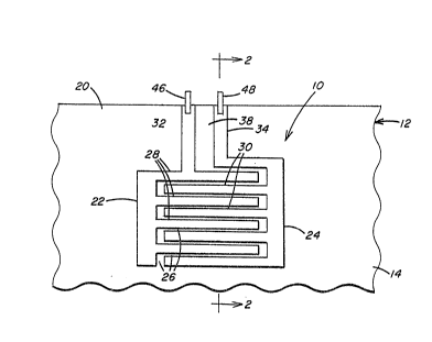
Referring to Figures 1 and 2, a moisture sensor 10,
which embodies the present invention, is incorporated in a
conventional trilayer windshield 12 which includes an outer glass ply
14, inner glas~ ply 16 and flexible interlayer 18. The sensor 10 may
15 be positioned anywhere on the windshield 12, but preferably is located
in an area that is swept by the windshield wipers (not shown) as they
clear the viewing area of the windshield 12.
In the particular embodiment of the invention illustrated in
Figures 1 and 2, the outer surface 20 of the outer ply 14 includes two
20 electroconductive members 22 and 24 spaced apart and electrically
insulated from each other by gap 26 of predetermined width. Although
not limiting in the present invention, the gap 26 is preferably not
greater than the width of a rain drop or mist droplet that may impact
or accumulate on the windshield 12. Unlike other moisture sensors,
25 there is no protective coating over the members 22 and 24 so that they
are exposed. As a result, the members 22 and 24 should be abuse
resistant, ~.e. abrasion, solvent, and weather resistant.
The members 22 and 24 may be positioned along the outer
surface 20 of ply 14 by any technique tha~ will not adversely affect
30 the optical quality of the windshield 12 and may be any of a number of
different types of electroconductive coatings or materials, as
disclosed ln U.S. Patent No. 4,831,493 ~o Wilson et al., which
.. ~.
.
~r~
- 7 - 2~31~4
Although not limiting in the
present invention, the members 22 and 24 are preferably an
electroconductive film, such as a tin o~ide coating, deposited on the
surface 20 of ply 14 by vacuum or pyrolytic depositlon techniques.
5 The members 22 and 24 may be interdigitated with pro~ections 28 of
member 22 positioned between and spaced from complementing
projection 30 of member 24. The interdigitation increases the length
of the interface between members 22 and 24, as will be discussed
later. Gap 26 electrically insulates pro~ections 28 from
10 pro~ections 30.
It should be noted that the thinner the coatings 22 and 24,
the better a windshield wiper (not shown) can remove water accumulated
in the gap 26 as the wiper sweeps acros~ sensor 10, as will be
discussed later.
With continued reference to Figures 1 and 2, the sensor 10
also includes lead members 32 and 34 which extend from members 22 and
24, respectively, along surace 20 of outer ply 14 and terminate at
edge 36 of the windshield 12. Although not limiting in the present
invention, in the particular embodiment illustrated in Figures 1 and
20 2, the leads 32 and 34 are ad~acent to each other, separated by a gap
38 (shown only in Figure 1) of predetermined width. The lead
members 32 and 34 are electrically connected to a controller 40 as
shown in Figure 3, which monitors the sensor 10 as will be discussed
later. Although not limiting in the present invention, controller 40
25 includes an AC signal generator 42 and sensor monitor 44 and is
connected to leads 32 and 34 by wires 46 and 48, respectively. As
with members 22 and 24, lead members 32 and 34 are uncoated so they
should be abrasion, solvent, and weather resistant. Lead members 32
and 34 may be applied in any convenient manner known in the art and
30 are preferable a tin oxide coatlng applied to surface 20 at the same
time and in the same manner as members 22 and 24 are applied.
..~ ~
2 ~
-- 8 --
The sensor 10 has specific characteristics based on its
particular configuration, such as for example its impedance. These
characteristics may change when moisture is on the sen~or 10. As a
result, the presence of moisture on the sensor 10 can be determined by
5 monitoring such a characteristic of the sensor 10. However, during
operation of the moisture sensor 10 as described in this disclosure,
it has been ob~erved that moisture or other deposits which form an
electrically conductive surface, e.g. salt or the vehicle body (not
shown) that surrounds the windshield 12, may electrically interconnect
10 the leads 32 and 34, shorting a portion of sensor circuitry S0 (shown
schematically in Figure 3) formed by members 22 and 24 and leads 32
and 34 so as to activate the windshield wiper motor when it is not
required to operate. To avold this condition, the present invention
provides Por a spacing between the lead3 32 and 34 relative to the
15 spacing between ad~acent pro~ections 28 and 30 of members 22 and 24,
respectively, such that a monitored characteristic of the sensor 10
will indicate ~he overall moisture condition of the sensor 10. To put
it another way, based on the relative width of gap 38 between leads 32
and 34 as compared to the width of gap 26 between pro~ections 28 and
20 30, the characteristic of the sensor 10 monitored by the controller 40
varies depending on the following operating conditions~ when
sensor 10 is dry; (2) when water electrically interconnects leads 32
and 34 only; (3) when water electrically interconnect~ the
pro~ections 28 and 30 only; (4) when both the proJections 28 and 30
25 and leads 32 and 34 are electrically interconnected by water on the
sensor 10~
Al~hough not limited in the present invention in one
particular embodimentg the monitored characteristic of the sensor 10
is its impedance. Impedance is expressed in terms of its magnitude in
30 ohms and the phase shift ln degrees between the current and voltage
waves of the sensor 10 when driven by generator 42 as the sensor 10
changes from being highly resistive in nature, i.e. having a low phase
2~3~
angle, to highly capacitive, i.e. having a high phase angle, In the
present invention, the relative spacing between the leads 32 and 34
and pro~ections 28 and 30 is such that the impedance of the sensor 10
under operating conditions ~1) and (2) is significantly different from
5 its impedance under operating conditions (3) and (4). Based on the
monitored impedance of the sensor 10, controller 40 can either
activate a wiper motor 78 (shown in Figure 3 only) when the monitored
impedance is indicative of moisture bridging members 22 and 24, i.e.
operating conditions (3) or (4)~ or either not actuate or inactivate
10 the wiper motor 52 when the monitored impedance is indicative o~
operating conditions (1) or (2).
Figure 3 is a schematic of a circuit 50 of the sensor 10
with the interdigitated pro~ections 28 and 30 and leads 32 and 34
being represented by capacitors 54 and 56, respectively. Signal
15 generator 42 powers the sensor lO through leads 32 and 34. Although
not limiting in the present inventionJ in the particular embodiment
where the impedance of the sensor 10 is being monitored, the
monitor 44 includes circuitry to monitor the current in the sensor 10
and the voltage across the sensor 10. As an alternative, either the
20 current or voltage may be fixed so that only the other has to be
monitored by the monitor 44. Variations in the impedance of the
sensor lO as measured by monitor 44, are monitored by controller 40
which includes a bandpass circuit or a filter that will activate the
wiper motor 52 only when the sensor lmpedance has a predetermined
25 relationship relative to a predetermined reference value or in the
alternative, iæ within a predetermined range, indicative of the
condition when moisture has accumulated on the sensor lO. In
particular, when there is no moisture accumulation between member
projections 28 and 30 of the cenSor lO, the sensor 10 will have an
30 impedance indicative of the operating condition~ ~1) or (2) and
controller 40 will not activate or deactivate the wiper motor 52.
However, when water accumulates between pro~ections 28 and 30 of the
lO 20310~
sensor 10, the sensor 10 will have an impedance indicative of
operating conditions (3) or (4). Under the latter condition,
controller 40 will generate a signal which will activate the wiper
motor 52.
Testing was performed to examine the variations in the
impedance of the sensor 10 under different operatlng conditions and
signal inputs. In the particular embodlment of the sensor 10 used
during testing, the coating members 22 and 24, including
pro~ections 28 and 30, respectively, and leads 32 and 34 were a
]0 transparent, tin oxide film applied by to a glass surface by pyrolytic
deposi~ion techniques, as taught in U.S. Patent No. 3,677,814 to
Gillery, providing a surface resistivity preferably in the range of 100 to
700 ohms per square. The leads 32 and 34 were approximately 9/32 inches
15 (7.1 mm) wide with the gap 38 between the leads being approximately
5/8 to 3/4 lnches (16 to 19 mm). Each pro~ection 28 and 30 was
approximately 3/16 inches (0.48 cm) wide with the gap 26 between the
pro~ections being approximately l/16 to 5/32 inches (1.6 to 4.0 mm).
The testing wa3 performed using a Hewlett Packard Model 4194A
20 Impedance/Gain-Phase Analyzer. Table l presents the test results at
selected input signal frequencies and are lndicative of the overall
test results. Each impedance value in Table l, expressed in terms o~
its magnitude and phase angle, represents the impedance for the
particular sensor configuration at a particular ~requency and under
25 the particular operating condition.
A -'xJ~
~3~
11
Table 1: Impedance of Sensor 10
Si~nal Input Frequency
5Operatin~ Condition 255 HZ 505 HZ _ l 000 HZ 1.978 HZ
Condition (1)
No Moisture on Sensor 5.8MQ @ 86 3MQ @ 86 1.6MQ @ ~6 0.81MQ @ 86
1 0 .... ~
Condition (2)
Moisture on Leads Only 119Kn @ 1.8 ll9KQ @ 2.6 118KQ @ 4.3 117KQ @ 7.9
. . . _ _
15Condition (3)
Moisture on
Projections Only 24KQ @ 0.32 24KQ @ 0.39 24KQ @ 0.33 24KQ @ 0.45
_ _ ..... . . ___
20Condition (4)
Moisture on Leads
and Pro~ection 21KQ @ 0.52 21KQ @ 0.41 21KQ @ 0.47 21KQ @ 0.71
Referring to Table 1, it can be seen that the magnitude of
the impedance of sensor 10 under operating condition.s (1) and (2) at
the selected input frequencies is almost Pive times ~he impedance of
the sensor 10 under operating conditions (3) and (4). In addition,
the reduction in phase angle difference from nearly 90 to nearly 0
30 indicates that as moisture coats the sensor 10, the sensor 10 changes
from being highly capacitive to highly resistive in nature.
In the previous discussion, the monitored characteristic of
the sensor 10 used to activate the wiper motor 52 was the sensor
impedance. However, other characteristics of the sensor 10 which
35 change when moisture is on the sensor 10 may be used to monitor the
sensor operation conditions. Although not limiting in the present
invention, the reactance of the sensor 10 can be monitored and used to
activate wiper motor 52. The reactance is the reactive component of
impedance, which when added vectorially to the resistive component,
2 ~ 3 ~
,
- 12 -
forms the total impedance. Table 2 lllustrates the reactance of the
sensor 10 based on the impedance values shown in Table 1.
Table 2: Reactance of Sensor 10
Si~nal Input Freauenc~
Operatin~ Conditions 255 HZ 505 HZ1JOOO HZ 1,978 HZ
Condition (1)
No Moisture on Sensor 3.8Mn 4.0Mn1.6MQ 0.81MQ
.... . _ . . . __
Condition (2)
Moisture on Leads Only 3.7~Q 5.4KQ8.9KQ 16.1KQ
Conditlon (3)
Moisture on
ZO ProJections Only0.13KQ 0.16KQ 0.14KQ0.19KQ
Condition (4)
Moisture on Leads
and Pro~ectionsO.l9KQ 0.15KQ 0.17KQ0~26KQ
As can be seen from Table 2, the reactance of the sensor 10
- under operating conditions (3) and (4) is in the range of about 20 to
30 85 times less than the reactance of the sensor under operating
condition (2) and is several orders of magnitude less than the
reactance under operating condition (1). Because of the large
difference between the s~nsor reactance under activating and
non-activating conditions 9 con~roller 40 can be precisely ad~usted to
; 35 activate the motor 52 only under the proper operating conditions.
In the previous discussion, it was shown that the impedance
and reactance of the sensor 10 are signlficantly different under
operating conditions (1) and (2) as compared to operating conditions
(3) and (4) . However, it should be appreciated that the magnitude of
40 the measurable difference depends on several fac~ors including, but
2~3 ~ ~L~
not limited to, the frequency of the power source, the monitored
characteristic of the sensor, e.g. impedance or reactance, the
sensitivity of the monitoring control clrcuit, and the sensor
configuration, and in particular the relative spacing between
5 pro~ections 2~ and 30 as compared to the spacing between leads 32 and
34. In practice, once the sensor configuration is set and the power
source i9 established, the control circuitry of the controller 40 is
designed to activate the wiper motor S2 only when the monitored
characteristic of the sensor is within or exceeds a predetermined
10 activation range which, in turn is based on the overall sensor
design. Although the charac~eristic of the sensor 10 monitored during
testing, i.e. the impedance and reactance, changed on the order of 5
times to several orders of magnitude depending on the operating
conditions as shown in Tables 1 and 2, it is obvious that depending on
15 the sensitivity of the sensor controller 40, much smaller variations
in the measured characteristlc can be used to activate the wiper
motor 52. It i5 believed that measurable differences as little as 1
to 2% or less can be used to activate the wiper motor 52~
When activated, the wiper motor 52 may operate to put the
20 wipers in one of several modes. If desired, the windshleld wipers
(not shown) may make a single pass across the windshield 12 to clear
any accumulated water from the sensor 10 or operate for a given time
period or set number of passes. In addition, the control circuitry of
windshield wipers (not shown) may be such tha~ if the motor 52 is
25 repeatedly activated so as to move the wipers to make a predetermined
number of passes within a set time period, the mo~or 52 will remain
activated until it is manually switched off by the vehicle opera~or.
The sensor 10 shown in Figures 1 and 2 may be used in a
windshield having a bilayer construction (not shown), i.e. a
30 windshleld having a single outer glass ply and an inner
impact-absorbing antilacerative ply, with the members 22 and 24 and
leads 32 and 34 of the sensor 10 positioned along the outer surface of
- 14 - ~ ~ 31 ~ ~
the glass ply in a manner as discussed previously. In addition, the
sensor 10 may be used in combination with an electrically heated
windshield as disclosed in U.S. Patent No. 4,820,902 to Gillery.
Furthermore, the sensor lO is not limited to use only on the outboard
5 surface of a windshield. For example, the sensor 10 may be used to detect
fog or ice on the inboard surface of vehicle window by locating members 22
and 24 on the inboard surface of the glass ply.
Unlike other rain sensors which constantly monitor variations
10 in capacitance caused by moisture absorbent coatings or dielectric
substrates, there are no variations in sensor 10 due to changes in
moisture absorption because there is no coating over coating
members 22 and 24 or leads 32 and 34 and there is no water absorbent
dielectric positioned between ~he members or lead. The sen~ors of the
15 present invention requires only that the spacing between the leads 32
and 34 relative to the spacing between the pro~ections 28 and 30 of
members 22 and 24 be such that a monitored characteristic of the
sensor is measurably different under the different operating
conditions.
The forms of this invention shown and described in thls
disclosure represent illustrative embodiments and it is understood
that various changes may be made without departing from the scope of
the invention as defined in the following claims.