Note: Descriptions are shown in the official language in which they were submitted.
2031107
FILM CASSETTE
BACKGROUND OF THE INVENTION
Field of the Invention
The invention relates generally to the field of
photography, and particularly to a film cassette
containing roll film. More specifically, the invention
relates to a film cassette that is capable of
automatically advancing a non-protruding film leader to
the exterior of the cassette shell responsive to
unwinding rotation of a film spool within the shell.
Descri~tion of the Prior Art
In conventional 35mm film manufacturers' cassettes,
such as manufactured by Eastman Kodak Co. and Fuji Photo
Film Co. Ltd., the filmstrip is wound on a flanged spool
which is rotatably supported within a cylindrical shell.
A leading or forward-most section of the filmstrip
approximately 2 1/3 inches long, commonly referred to as
a ~film leaderl', normally protrudes from a light-trapped
slit or mouth of the cassette shell. One end of the
spool has a short axial extension which projects from the
shell, enabling the spool to be turned by hand. If the
spool is initially rotated in an unwinding direction, the
film roll inside the shell will tend to expand radially
since the inner end of the filmstrip is attached to the
spool, and the
~ ,;
20311Q7
fogged leader section protruding from the slit will
remain stationary. The film roll can expand
radially until a firm non-slipping relation is
established between its outermost convolution and
the inner curved wall of the shell. Once this
non-slipping relation exists, there is a binding
effect between the film roll and the shell which
prevents further rotation of the spool in the
unwinding direction. Thus, rotation of the spool in
the unwinding direction cannot serve to advance the
filmstrip out of the shell, and it is necessary in
the typical 35mm camera to engage the protruding
leader section to draw the filmstrip out of the
shell.
A 35mm film cassette has been proposed
which, unlike conventional film cassettes, can be
operated to automatically advance a film leader out
of the cassette shell by`rotating the film spool in
the unwinding direction. The film leader originally
is located entirely inside the cassette shell.
Specifically, in U.S. Pat. No. 4,423,943, granted
January 3, 1984, there is disclosed a film cassette
wherein the outermost convolution of the film roll
wound on the film spool is radially constrained by
respective circumferential lips of two axially
spaced flanges of the spool to prevent the outermost
convolution from contacting an inner curved wall of
the cassette shell. The trailing end of the
filmstrip is secured to the film spool, and the
forward or leading end of the filmstrip is slightly
tapered purportedly to allow it to freely extend
from between the circumferential lips and rest
against the shell wall at a location inwardly of a
non-lighttight film passageway to the outside of the
cassette shell. During initial unwinding rotation
2031107
of the film spool, the leading end of the filmstrip
is advanced along the shell wall until it reaches an
inner entrance to the film passageway. Then, it is
advanced into and through the film passageway to the
outside of the cassette shell. The passageway has a
width that is less than the width of the filmstrip,
thus resulting in the filmstrip being transversely
bowed as it is uncoiled from the film spool, and
thereby facilitating movement of the film edges
under the circumferential lips of the flanges.
However, severe transverse bowing of the filmstrip
in order to move its longitudinal edges under the
circumferential lips of the flanges may damage the
filmstrip.
Like the type of film cassette disclosed in
U.S. Pat. No. 4,423,923, commonly assigned Pats. No.
4,834,306 granted May 30, 1989, and No. 4,848,693,
granted July 18, 1989, each disclose a film cassette
that is capable of automatically advancing a
non-protruding film leader to the outside of the
cassette shell in response to rotation of the film
spool in the unwinding direction. Specifically,
there is disclosed a film cassette wherein a film
roll is wound on a spool between a pair of coaxially
spaced, independently rotatable flanges. The two
flanges have respective circumferential annular lips
which prevent the outermost convolution of the film
roll, including its leading end, from
clock-springing into contact with the interior wall
of the cassette shell. When the spool is initially
rotated in the unwinding direction, the flanges may
momentarily remain stationary and the film roll,
since its inner end is secured to the spool, tends
to expand radially to ensure a firm non-slipping
relation between the outermost convolution and the
2031107
annular lips. Once the non-slipping relation
exists, continued rotation of the spool will
similarly rotate the flanges. This allows
stationary internal spreaders to deflect successive
portions of the annular lips to an axial dimension
exceeding the film width, in turn allowing the
leading end of the film roll to be freed from the
radial confinement of the annular lips and to be
advanced into and through a lighttight film
passageway to the outside of the cassette shell. A
stripper-guide located adjacent an inner entrance to
the film passageway diverts the leading end of the
film roll into the passageway by being received
between the leading end and the next-inward
convolution of the film roll responsive to unwinding
rotation of the spool.
Somewhat similarly, commonly assigned U.S.
Pat. No. 4,883,235, granted November 28, 1989
discloses a film cassette wherein a film roll whose
outermost convolution is a film leader is coiled
about a spool rotatable within the cassette shell, a
pair of flexible independently rotatable flanges are
coaxially arranged on the spool to radially confine
the film leader within respective skirted
peripheries of the flanges to prevent the leader
from substantially contacting an interior wall of
the cassette shell, and a film stripper-guide
projecting from the interior wall is received
between a leading end of the film leader and the
next-inward convolution of the film roll to free the
leader from the flanges and guide the leader through
a lighttight film passageway to the exterior of the
cassette shell responsive to rotation of the spool
in a film unwinding direction. Specifically, the
stripper-guide frees the film leader from the
20311~1
flexible flanges by inducing the leader to flex the
flanges away from one another at their skirted
peripheries during unwinding rotation of the spool.
Moreover, the film leader and at least one of the
flanges include mutual engagement means for
maintaining the leading end of the leader spaced at
least a minimum radial distance from the next-inward
convolution of the film roll sufficient to locate
the leading end within range of the stripper-guide,
to ensure that the leading end will be advanced over
the stripper-guide responsive to rotation of the
spool in the film unwinding direction.
SUMMARY OF THE INVENTION
It has been found, for example with the
film cassette disclosed in commonly assigned U.S.
Pat. No. 4,883,235, when the film spool is rotated
in the unwinding direction, initial thrusting of the
leading end of the film leader through the
passageway to the exterior of the cassette is
resisted by the light-trapping plush in the
passageway. Simultaneously, further resistance to
film movement is presented by the two flanges when
the leader must flex them away from one another to
escape the confinement of the flanges. These two
resistive forces necessarily increase the torque
required to rotate the film spool in the winding
direction.
According to the invention, the torque
required to rotate the film spool in the winding
direction is advantageously lessened by designing a
film cassette in which the two resistive forces
occur successively, rather than substantially
simultaneously as in U.S. Pat. No. 4,883,235. This
is achieved by thrusting the leading end of the film
leader clear of the light-trapping plush in the film
20311Q7
passageway before the leader must flex the two
flanges away from one another.
Thus, the invention be summarized as
follows:
A film cassette comprising (a) a spool core
supported for rotation in an unwinding direction to
thrust a leader section of a filmstrip coiled about
the spool core through a passageway with
light-trapping means to the exterior of the cassette
and (b) a pair of flanges arranged in spaced
relation along the spool core for overlying opposite
longitudinal edges of the filmstrip to radially
confine the filmstrip coiled about the spool core
and adapted to permit the longitudinal film edges to
force the flanges farther apart to allow the
filmstrip to escape the confinement of the flanges
to permit the leader section to be thrust outside
the cassette, is characterized in that:
said leader section of the filmstrip
includes integral means at the longitudinal film
edges for permitting the leader section to be thrust
through the passageway to at least partially clear
of the light-trapping means before the longitudinal
film edges begin to force the flanges farther apart,
whereby when the spool core is rotated in the
winding direction the leader section will first
overcome any resistance the light-trapping means
- initially presents to film movement and the
longitudinal film edges will then overcome any
resistance the flanges initially present to being
forced farther apart.
BRIEF DESCRIPTION OF THE DRAWINGS
FIG. 1 is an exploded perspective view of a
film cassette according to a preferred embodiment of
the invention;
~ 20311~7
FIG. 2 is an elevation view of the film
cassette, illustrating the cassette shell open to
reveal a film roll coiled about a film spool;
FIG. 3 is an end view partly in section of
the cassette shell, the film roll and the film
spool, illustrating the manner in which the film
roll is originally stored on the film spool;
FIGS. 4, 5, 6 and 7 are end views similar
to FIG. 3, illustrating the manner in which the film
roll is unwound from the film spool;
FIGS. 8 and 9 are elevation views of the
film roll and the film spool, illustrating the
manner in which the film roll is originally stored
on the film spool;
FIGS. 10 and 11 are elevation views similar
to FIGS. 8 and 9, illustrating the manner in which
the film roll is unwound from the film spool;
FIG. 12 is an e~ploded perspective view of
the film spool without the film roll; and
FIG. 13 is an elevation view partly in
section of the film roll and the film spool,
illustrating the manner in which one of a pair of
film confining flanges of the spool may be fixed to
the spool for concurrent rotation with the spool.
DETAILED DESCRIPTION OF THE PREFERRED EMBODIMENT
The invention is disclosed as being
embodied preferably in a 35mm film cassette.
Because the features of this type of film cassette
are generally well known, the description which
follows is directed in particular to elements
forming part of or cooperating directly with the
disclosed embodiment. It is to be understood,
however, that other elements not specifically shown
or described may take various forms known to persons
of ordinary skill in the art.
2031107
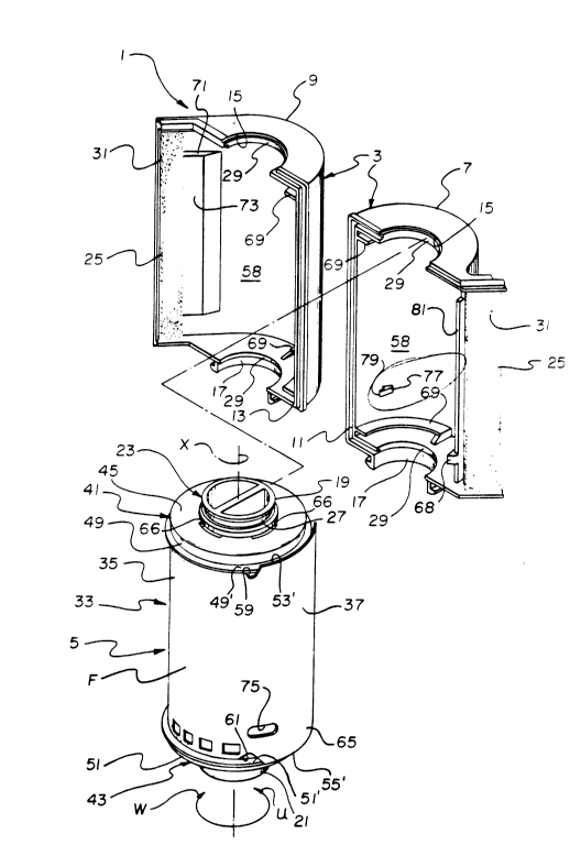
Referring now to the drawings, FIGS. 1, 2
and 12 depict an improved 35mm film cassette 1
comprising a light-tight cassette shell 3 and a film
spool 5 which is rotatable about an axis X in film
unwinding and winding directions U and W within the
cassette shell. The cassette shell 3 consists of
two shell halves 7 and 9 which are mated along
respective grooved and stepped edge portions 11 and
13. The mated halves 7 and 9 define upper and lower
aligned circular openings 15 and 17 for relatively
shorter and longer opposite open-end pieces 19 and
21 of a spool core or hub 23, and they define a
narrow relatively-straight film passageway 25 to the
exterior of the cassette shell 3. The longer and
shorter open-end pieces 19 and 21 of the spool core
23 each include an annular peripheral groove 27
which mates with a corresponding edge portion 29 of
the respective openings 15 and 17 in the cassette
shell 3 to rotatably support the film spool 5 for
rotation about the axis X in the film unwinding and
winding directions U and W. A known black velvet or
plush material 31 lines the interior of the film
passageway 25 to prevent ambient light from entering
the film passageway.
A roll 33 of 35mm filmstrip F is coiled
about the spool core 23 to form successive film
convolutions. As shown in FIG. 3, the film roll 33
includes an outermost convolution which comprises
part of a film leader 35 having a leading end
portion or forward-most portion 37, and it includes
a next-inward convolution 39 coiled behind the
outermost convolution. The inner or trailing end of
an innermost convolution 40 of the film roll 33 is
secured to the spool core 23 using known attachment
means, not shown. See FIG. 13.
2031~
A pair of upper and lower identical, very
thin, flexible film constraining flanges 41 and 43
are coa~ially spaced along the spool core 23 as
shown in FIGS. 1, 2, 8, 12 and 13. The two flanges
41 and 43 comprise respective integral disks 45 and
47 and respective integral annular lips or skirts 49
and 51 which circumferentially extend from the
disks. The two disks 45 and 47 cover opposite
substantially flat sides of the film roll 33 which
are defined by corresponding opposite longitudinal
edges 53 and 55 of each successive convolution of
the film roll, and they have respective central
holes 56 through which the spool core 23 coaxially
e~tends to permit rotation of the spool core
relative to the flanges 41 and 43. See FIG. 12.
Respective circumferential recesses 57 are provided
in the spool core 23 for supporting the flanges 41
and 43 at their disks 45 and 47 to permit the
flanges to be independently rotated about the axis
X. The two recesses 57 are sufficiently spaced from
one another along the spool core 23 to maintain
respective inner faces 45' and 47' of the disks 45
and 47 slightly spaced from the longitudinal edges
53 and 55 of each successive convolution of the film
roll 33. See FIG. 13. The annular lips 49 and 51
overlap the film leader (outermost convolution) 35
of the film roll 33 radially outwardly of the
longitudinal edges 53 and 55 of the leader to
radially confine the leader to thus prevent it from
radially expanding or clock-springing into
substantial contact with an interior curved wall 58
of the cassette shell 3. Respective lip-receiving
notches 59 and 61 are cut in the film leader 35
along its longitudinal edges 53 and 55 to receive
peripheral sections 49' and 51' of the annular lips
2031107
--10--
49 and 51. This allows edge-sections 53' and 55' of
the film leader 35, along the leading end portion 37
of the leader, to overlap the annular lips 49 and 51
radially outwardly to thus maintain the leader at
its leading end portion spaced a radial distance D
from the next-inward convolution 39 of the film roll
33. See FIGS. 4 and 9. The leading end portion 37
has a forward edge 63 inclined from the edge-section
53' to the other edge-section 55' to form a
forward-most tip or tab 65 of the leading end
portion which, like the latter edge-section,
overlaps the annular lip 51 radially outwardly. See
FIGS. 1, 2, 8 and 9.
The two flanges 41 and 43 have a plurality
of concentric arcuate slots 66 cut in their
respective disks 45 and 47 to longitudinally extend
in the film unwinding and film winding directions U
and W. Engagement means in the form of respective
hook-like members 67, located on the short and
longer open-end pieces 19 and 21 of the spool core
23, are normally located in the concentric slots 66
for movement along the slots into engagement with
the flanges 41 and 43 responsive to rotation of the
spool core relative to the flanges in the unwinding
direction U and for movement along the slots out of
engagement with the flanges responsive to rotation
of the spool core relative to the flanges in the
winding direction W. See FIGS. 12 and 13.
Preferably, each of the hook-like members 67 has an
end face 67' that is beveled to ease the hook-like
member out of one of the concentric slots 66
responsive to rotation of the spool core 23 relative
to the flanges 41 and 43 in the winding direction W,
in the possible event the spool core is rotated
relative to the flanges far enough in the winding
2~31107
--ll--
direction to back the hook-like member out of the
slot.
A film stripper-guide 68 projecting from
the interior wall 58 of the cassette half 7 is
positioned immediately inward of the inner entrance
to the film passageway 25 to be received between the
leading end portion 37 of the film leader 35 and the
next-inward convolution 39, close to the
forward-most tip 65 of the leading end portion, to
pick up the leading end portion and guide it into
the film passageway responsive to rotation of the
spool core 23 in the unwinding direction U. See
FIGS. 1 and 4-7. The leading end 37 portion will be
advanced over the stripper-guide 68 and into the
film passageway 25, rather than between the
stripper-guide and the next-inward convolution 39,
because it is spaced the radial distance D from the
latter convolution. Thus, as shown in FIG. 4, the
leading end 37 portion will be located within range
of the stripper-guide 68 due to such spacing D from
the next-inward convolution 39.
After the leading end portion 37 of the
film leader 35 is advanced over the stripper-guide
68 and into the film passageway 25 as shown in FIGS.
4-6, it will be advanced to the outside of the
cassette shell 3 as shown in FIGS. 7, 10 and 11.
Then, the longitudinal edges 53 and 55 of the film
leader 35 will start to gently fle~ respective
arcuate portions of the two flanges 41 and 43
axially away from one another, first to allow the
notches 59 and 61 to separate from the lip sections
49' and 51', and second to allow successive
longitudinal sections of the leader to exit from
between the flanges to the outside of the cassette
shell 3. The local flexing of the flanges 41 and 43
2031107
occurs because the film width WF between the
longitudinal film edges 53 and 55 is slightly
greater than the axial spacing AS between the
annular lips 49 and 51. Moreover, successive
convolutions of the film roll 33 have a resistance
to transverse bowing that is greater than the
resistance of the flanges 41 and 43 to be locally
flexed. A pair of flat curved bearing members 69
extend from the interior wall 58 of the cassette
shell 3 to lie flatly against successive arcuate
portions of the two disks 45 and 47 as the flanges
41 and 43 are locally flexed axially away from one
another, to thereby assure return of the flexed
portions of the flanges to their normal original
non-flexed condition. See FIGS. 1 and 2.
A film flattening member 71 projects from
the interior wall 58 of the cassette half 9 in the
vicinity of the inner entrance to the film
passageway 25 and the stripper-guide 68 to support
successive longitudinal sections of the film leader
35, beginning with its leading end portion 37,
substantially flat as those sections are advanced to
the passageway. See FIGS. 6 and 7. The
light-trapping plush 31 within the film passageway
25 is elevated along the passageway slightly beyond
a longitudinal center line L of the passageway. The
film flattening member 71 as shown in FIG. 3
projects almost to the center line L in order to
support successive sections of the film leader 35
substantially flat at the center line. See FIGS. 6
and 7. Preferably, a substantially planar
film-supporting face 73 of the flattening member 71
is spaced .005n - .030" short of the center line L,
and extends widthwise of the film passageway 25 as
shown in FIG. 1.
2031107
-13-
Optionally, a slot 75 is cut in the film leader
(outermost convolution) 35 substantially proximate its
leading end portion 37. A tooth 77 fixed to the interior
wall 58 of the cassette half 7 has a free pointed end 79
which is positioned to be received in the slot 75 to thus
engage the film leader 35, when the film spool 5 is
rotated in the winding direction W as shown in FIG. 3,
and to exit the slot to thus disengage the leader, when
the film spool is rotated in the unwinding direction U as
shown in FIG. 4. The engagement of the film leader 35
and the tooth 77 responsive to rotation of the film spool
5 in the winding direciton W prevents the leading end
portion 37 of the leader from coming to rest between the
stripper-guide 68 and the next-inward convolution 39.
O~eration
When the spool core 23 is initially rotated in the
film unwinding direction U, the two flanges 41 and 43
momentarily tend to remain stationary and the film roll
33, since its inner end is attached to the spool core,
will expand radially or clock-spring to force the film
leader 35 firmly against the annular lips 49 and 51 of
the flanges. Generally however, before the film roll 33
can be expanded radially to the extent a non-slipping
relation would be created between the film leader 35 and
the annular lips 49 and 51 as in commonly assigned U.S.
Pats. No. 4,834,306 and No. 4,484,693, the hook-like
members 67 will have moved along the respective slots 66
into engagement with the two flanges 41 and 43 to fix the
flanges to the spool core. Then, further rotation of the
spool core 23 will similarly rotate the flanges 41 and
43. As a result, the leading end 37 portion of the film
leader 35 will be
,,
~,
2 0 ~ 7
advanced over the stripper-guide 68, into the
passageway 25, and to the outside of the cassette
shell 3. Then, successive arcuate portions of the
flanges 41 and 43 will be flexed axially away from
one another as shown in FIG. 11. This first allows
the notches 59 and 61 to separate from the lip
sections 49' and 51', and then it allows successive
longitudinal sections of the film leader 35 to e~it
from between the flanges to the outside of the
cassette shell 3. Since the stripper-guide 68
initially picks up the leading end portion 37 of the
film leader 35 close to its forward-most tip 65, the
forward edge 63 of the leading end portion might
initially be supported along a narrow ridge 81
forming one end of the interior wall 58 of the
cassette half 7. However,-the leading end 37
portion will tend to back away from the ridge 81 and
move against the film-supporting face 73 of the
flattening member 71 as shown in FIG. 6.
Optimally, the leading end portion 37 of
the film leader 35 has a predetermined length P as
shown in FIG. 10, which is not less than an arc of
45 degrees nor more than an arc of 120 degrees along
the annular lip 51 of the flanges 43. This length P
ensures that the forward-most tip 65 of the leading
end portion 37 will be advanced to the outside of
the cassette shell 3 before successive arcuate
portions of the flanges 41 and 43 are flexed axially
away from one another as shown in FIG. 11.
If the spool core 23 is rotated in the film
winding direction W after some length of the
filmstrip F has been advanced from the cassette
shell 3, the spool core is free to rotate relative
to the two flanges 41 and 43 because the hook-like
members 67 can move along the respective slots 66
2Q~l~a7
out of engagement with the flanges. This permits
the flanges 41 and 43 to be independently rotated in
the winding direction W, though at a slower speed
than the spool core 23 is rotated in that
direction. Each of the hook-like members 67 may
back out of one of the slots 66 and into the next
slot during continued rotation of the spool core 23
in the winding direction W. At the same time, the
filmstrip F will be rewound onto the spool core 23
between the flanges 41 and 43. The spool core 23 is
rotated in the winding direction W substantially
until the slot 75 in the film leader 35 receives the
free end 79 of the tooth 77 to thus engage the film
leader to the tooth.
It has been found that by fixing at least
one of the two flanges 41 and 43 to the spool core
23 during unwinding rotation of the film spool 5, as
contrasted with allowing the flange to remain
rotatable independently of the spool core as in
commonly assigned U.S. Pats. No. 4,834,306 and No.
4,848,693, there is immediately effected a
frictional relationship between the film leader 35
and the skirted periphery of the flange which
improves the ability of the film spool to thrust the
film leader through the lighttight passageway 25 to
the exterior of the cassette shell 3. In
particular, the frictional relationship increases
the pushing force the spool core 23 will apply to
the film leader 35 to propel the leader out of the
cassette shell 3. Moreover, it has been found that
by allowing both of the flanges 41 and 43 to be
rotated independently of the spool core 23 during
winding rotation of the film spool 5, as in commonly
assigned U.S. Pats. No. 4,834,306 and No. 4,848,693,
it is substantially ensured that the leader can be
2031107
rewound within the skirted peripheries 49 and 51 of
the flanges without being obstructed by the skirted
peripheries.
The invention has been described with
5 reference to a preferred embodiment. However, it
will be appreciated that variations and
modifications can be effected within the ordinary
skill in the art without departing from the scope of
the invention. E~or example, instead of including
10 the lip-receiving notches 59 and 61, the leading end
portion 37 of the film leader 35 could simply be
tapered along its edge-sections 53' and 55' to
permit the leading end portion to protrude outwardly
from between the two flanges 41 and 43 the
15 predetermined length P.