Note: Descriptions are shown in the official language in which they were submitted.
-2 0 3 ~
: ':
BACKGROUND OF THE INVENTION
Field of the Invention
The present invention relates generally to magnetic tape
cassettes and, more particularly, is directed to a magnetic tape
cassette having a cassette casing in which a tape-like record
medium is wound around reel hubs and housed and in which the
tape-like record medium is helically wrapped around a head drum
inserted into an opening portion of the cartridge to thereby
perform recording and/or reproduction in a helical scan fashion.
Description of the Prior Art
In order to miniaturize a helical scan type recording and
reproducing apparatus, a magnetic tape cassette is proposed, in
which one portion of a head drum having a rotary head is inserted
into a front surface side opening portion of a cassette casing
and a tape-like record medium, i.e. a magnetic tape housed in the
cassette caslng i6 brought in slidable contact with the
peripheral surface of the head drum.
In the aforementioned tape cassette, a tape guide having a
recess formed at front surface thereof is provided at the inside
of the front surface side opening portion of the cassette casing,
and the head drum is received by these recess. Also, the
magnetic tape is guided and helically wrapped around the head
drum by inclined guides having opposite inclination angles formed
at left and eight sides of the recess, whereby the rotary head
provided on the head drum obliquely scans the magnetic tape to
thereby perform the recording and/or reproduction in a helical
scan fashion.
Japanese Patent Laid-Open Gazette No. 64-73584 describes
other proposal of the above-mentioned magnetic tape cassette, in
which the tape guides having the inclined guides are molded
203~ 3~7
independently of the cassette casing and assembled inside the
opening portion of the cassette casing.
In this previously-proposed magnetic tape cassette, it is
needles to say that the tape guides provided inside the front
surface side opening portion of the cassette casing are molded
integrally with a cassette shell which forms the cassette casing.
Also, even in the magnetic tape cassette in which the tape guides
are molded independently of the cassette casing as described in
Japanese Patent Laid-Open Gazette No. 64-73584, the tape guides
must be secured to the cassette shell.
More particularly, the tape guides independently molded are
assembled in the inside of the opening portion of one cassette
shell (lower half) such that their central portions are engaged
with central pins and two side portions thereof are engaged to
restriction surfaces or engaging pins. Thus, the tape guides are
assembled in the inside of the opening portion of the cassette
casing under the condition such that they cannot be moved.
; There is then a risk that the head drum inserted into the
opening portion of the tape cassette cannot be received by the
tape guides satisfactorily.
That is, since the tape guides are secured to the cassette
casing, the tape cassette is not correctly loaded onto the
recording and reproducing apparatus. Further, if the head drum
is not precisely inclined more or less and so on, even when the
head drum is inserted into the opening portion of the cassette
casing, the head drum does not come in contact with the tape
guides correctly so that the magnetic tape is brought in contact
with the peripheral surface of the head drum unstably, causing a
trouble in the recording and/or reproduction.
OBJECTS AND SUMMARY OF THE INVENTION
2~3~3~7
Accordingly, it is a general object of the present invention
to provide an improved magnetic tape cassette which can eliminate
the aforenoted shortcomings and disadvantages encountered with
the prior art.
More specifically, it is an object of the present invention
to provide a magnetic tape cassette in which a recording and/or
reproduction can be carried out reliably.
It is another object of the present invention to provide a
magnetic tape cassette whose reliability can be increased.
It is still another object of the present invention to
provide a magnetic tape cassette in which cassette shells can be
prevented from being deformed.
It is a further object of the present invention to provide a
; magnetic tape cassette which can reduce a cost.
~- As an aspect of the present invention, the magnetic tape
cassette of the present invention has the opening portion into
which the head drum having the rotary head is inserted. The pair
of tape guide members which guide the tape-like record medium so
that the record medium is helically wrapped around the head drum
are provided in the inside of the opening portion so as to be
able to swing independently. Thus, when the head drum is inserted
into the opening portion, the two tape guide members is brought
in circumferential contact with the surface of the head drum
.,.. " .~ .
accurately. Therefore, the recording and/or reproduction can be
reliably carried out, which can increase reliability of the
magnetic tape cassette.
The above, and other objects, features and advantages of the
present invention will become apparent from the following
detailed description of illustrative embodiments to be taken in
conjunction with the accompanying drawings, in which like
-~ 2~3~3~7
.:
reference numerals are used to identify the same or similar parts
in the several views.
BRIEF DESCRIPTION OF THE DRAWINGS
Fig. 1 is a fragmentary plan view of a main portion of an
embodiment of a magnetic tape cassette according to the present
invention;
Fig. 2 is a cross-sectional view taken through the line A -
A of Fig. l;
Fig. 3 is a cross-sectional view taken through the line B -
B of Fig, 1;
Fig. 4 is a perspective view of a tape guide member used in
the present invention;
Fig. 5 is a perspective view showing an embodiment of the
, ~ magnetic tape cassette according to the present invention;
~'' Fig. 6 is a perspective view of the magnetic tape cassette
and a head drum of the present invention, and to which references
will be made in explaining a relationship therebetween;
Fig. 7 is a front view of the magnetic tape cassette of the
present invention and illustrating the condition such that a lid
is opened;
Fig. 8 is a plan view of the inside portion of the upper
shell of the magnetic tape cassette;
Fig. 9 is a plan view of the lower shell of the magnetic
. .. .. .
tape cassette;
Fig. 10 is a fragmentary plan view of the lower shell and
illustrating the condition such that the head drum i5 inserted
into the lower shell;
Fig. 11 is a perspective view of a braking mechanism of the
magnetic tape cassette of the present invention;
Fig. 12 is a plan view of the magnetic tape cassette and
- ~ 2~3~3~
. ,
illustrating the condition that the reel hubs are released from
being locked by the braking mechanism;
Figs. 13A and 13B are cross-sectional views used to explain
the operation of the present invention, respectively;
Fig. 14 is a cross-sectional view of the reel hub used in
the magnetic tape cassette of the present invention;
Fig. 15 is a perspective view of a protective plug of a mis-
erase preventing mechanism of the present invention;
Fig. 16 is a diagrammatic view of a section showing the mis-
erase preventing mechanism of the present invention from the
front side thereof;
Fig. 17 is a cross-sectional view taken along the line C -C
of Fig. 16;
-~ Fig. 18 is a cross-sectional view of a cassette magazine to
' ~ which the present invention is applied;
Fig. 19 is a schematic diagram showing an outline of a
ca~sette changer system to which the present invention is
applied; and
Fig. 20 is a schematic diagram used to explain how to take
the magnetic tape cassette out of the cassette magazine.
DETAILED DESCRIPTION OF THE PREFERRED EMBODIMENTS
An example of a magnetic tape cassette to which the present
invention is applied will be explained with reference to Figs. 1
to 10. The magnetic tape cassette of this embodiment is
constructed as an extremely small magnetic tape cassette.
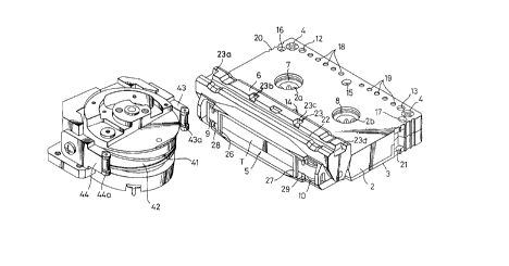
In Figs. 1 to 10, reference numeral 1 generally designates a
a cassette casing which~accommodates therein a magnetic tape on
and from which, for example, a PCM (pulse code modulated) signal
is recorded and reproduced. This cassette casing 1 is formed by
fastening an upper half or upper part 2 and a lower half or lower
- - ~ .
: ' 2~3~3~
, , .
part 3 by screws 4, and a lid 6 is rotatably supported to the
cassette casing so as to open and close an opening portion 5
formed on the front surface sides of both the upper and lower
parts 2 and 3.
A magnetic tape T is accommodated within the cassette casing
1, i.e. between the upper and lower parts 2 and 3 under the
condition such that the magnetic tape T is wound around a pair of
reel hubs 7 and 8 provided in correspondence with hub drive shaft
insertion apertures 2a, 2b and 3a, 3b. One portion of the
magnetic tape T is exposed to the front surface side opening
portion 5 under the condition such that the magnetic tape T is
extended between pinch rollers 9 and 10 serving as guide rollers
pivotally supported to both sides of the opening portion 5.
A braking mechanism 11 is provided within the cassette
casing 1 to brake the two reel hubs 7 and 8 when this magnetic
, -
tape cassette is not in use. Mis-erase preventing mechanisms 12
and 13 are provided at the upper and lower surface sides of the
cassette casing 1 at its two rear corner portions so as to
communicate with the upper and lower parts 2 and 3. Positioning
reference apertures 14, 15 and 16, 17 are formed through the
cassette casing 1 at its central front and back portions in the
front to back direction and at its two rear side portions in the
- lateral direction. A plurality of predetermined detection
apertures 18 and 19 are formed through the cassette casing at its
rear edge portion in the lateral direction. Further, grip
portions 20 and 21 are formed on the rear portions of two side
walls of the cassette casing 1.
A cassette changer engaging portion 23 ~23a, 23b, 23c and
23d) is formed along a guide groove 22 extending along the width
direction of the lid 6 which opens and closes the front surface
2~3~ 3~
' -
side opening portion 5 of the cassette casing 1.
In the magnetic tape cassette thus arranged, the magnetic
tape T acc~ -dated within the cassette casing 1 is recorded
and/or reproduced by a rotary head in a helical scan fashion.
More specifically, as shown in Fig. 6, a rotary head 41 is
rotated at a predetermined slant angle relative to a head drum
42, and the head drum 42 is partly inserted into the front
surface side opening portion 5 which is opened by rotating the
lid 6 of the cassette casing 1 in the upper or lower direction.
The magnetic tape T extended across the opening portion 5 is
slidably moved so as to be wound around the insertion side
peripheral surface of the head drum 42. Thus, when the rotary
head 41 is rotated, slant tracks across the magnetic tape T are
: :formed on the magnetic tape T.
; ~1In this embodiment, in order to ensure that the magnetic
tape T is brought in slidable contact with the head drum 42 in a
helical scan fashion, as shown in Figs. 7, 9 and 10, a pair of
tape guide members 24 and 25 whose guide portions are inclined in
the opposite direction are disposed in the insertion portion of
the opening portion 5 of the cassette casing 1 for the head drum
42 at their positions inside the guide rollers 9 and 10 such that
the tape guide members 24 and 25 can be vibrated and moved in the
lateral direction in an opposing fashion. When the head drum 42
: is inserted into the opening portion 5, the tape guide members 24
and 25 come in contact with the peripheral surface of the head
drum 42, and guide the magnetic tape T under the condition such
that the magnetic tape T is sandwiched between them and the
peripheral surface of the head drum 42.
Further, as shown in Figs. 6 and 10, the head drum 42 has at
its both side portions formed wing guides 43 and 44 which are
, ~ ~
~(~3~3~7
.
inserted between the pinch rollers 9, 10 and the tape guide
members 24, 25 in both side portions of the opening portion 5 of
the cassette casing 1. Rollers 43a and 44a are mounted on the
front end portions of the two wing guides 43 and 44, and brought
in slidable contact with the magnetic tape T, urging the magnetic
tape T against the tape guide members 24 and 25.
The wing guides 43 and 44 are inserted into the opening
portion 5 of the cassette casing 1 such that they are located
between supporting members 26 and 27 provided near the inside of
the opening portion 5 and tape projection preventing guide
protrusions 28, 29 positioned between the supporting members 26
and 27 and the pinch rollers 9 and 10.
The tape guide members 24 and 25 provided at the front
surface opening portion 5 of the cassette casing 1 will be
described more fully with reference to Figs. 1 to 4.
As illustrated, the tape guide members 24 and 25 are
symmetrically disposed at two sides of the front sur~ace side
opening portion 5 of the cassette casing 1, and the guide
portions thereof are inclined in the opposite direction.
Inner surfaces of the two tape guide members 24 and 25 are
formed as inclined surfaces of arcuate confiqurations of
diameters smaller than the diameter of the head drum 42 and which
are inclined in the opposite direction in the up and down
direction. Protruded supporting edge portions 24a, 24b and 25a,
25b are formed on the upper and lower portions of the inclined
inner surfaces of the tape guide members at a spacing slightly
wider than a width of the magnetic tape T. Guide surfaces 24c
and 25c are formed between these upper and lower supporting edge
portions 24a, 24b and 25a, 25b. Vertical columnar guide surfaces
24d and 25d are formed on the front surface continued to the
- 2~3~ 3~
inclined guide surfaces 24c and 25c. Front edge portions of
supporting end edge portions 24a, 24b and 25a, 25b are slightly
extended forward from the columnar guide surfaces 24d and 25d to
form receiving edge portions 24al, 24bl and 25al, 25bl, and
engaging protrusions 24a2, 24b2 and 25a2, 25b2 are formed on the
upper and lower opposing faces of the receiving edge portions
24al, 24bl and 25al, 25bl. Further, pressing edge portions 24e,
24f and 25e, 25f are formed on the upper and lower portions of
the outer ends of the columnar guide surfaces 24d and 25d in
association with the receiving edge portions 24al, 24bl and 25al,
25bl, respectively. Concave portions 24el, 24fl and 25el, 25fl
are formed on the front surfaces of the pressing edge portions
24e, 24f and 25e, 25f, respectively.
~- Further, bearing brackets 24g and 25g are protruded from the
. - ,.~ ,
tape guide members 24 and 25 at their outer surface side of the
guide surfaces 24c and 25c. Shaft apertures 24gl and 25gl of the
bearing brackets 24g and 25g are shaped as rectangular apertures
long in the lateral direction and protruded columnar support
edges 24g2 and 25g2 are formed on the inner peripheral surfaces
of the shaft apertures 24gl and 25gl at substantially the centers
thereof.
In the thus constructed tape guide members 24 and 25, the
bearing brackets 24g and 25g are inserted at their bearings 24gl
~~ i
and 25gl into shafts 131 and 132 protruded at the front surface
side opening portion 5 of the cassette casing 1, that is, at two
side portions of the front opening portion forming surface of the
front wall of the lower shell 3, and the lower surface sides of
the tape guide members 24 and 25 are placed on holding members
133 and 134 formed around the base portions of the shafts 131 and
132, whereby the lower surface sides of the tape guide members 24
203~3~7
.... ~ .
and 25 are supported under the condition such that they are
floated from the inner surface of the lower shell 3 with a
predetermined spacing. Therefore, the tape guide members 24 and
25 can be rotated relative to the shafts 131 and 132 and also can
be inclined in the lateral direction, or swung about connecting
points between the support edges 24g2 and 25g2 of the shaft
apertures 24gl and 25gl and the shafts 131 and 132. Further, the
tape guide members 24 and 25 can be moved in the lateral
direction by the oblong apertures 24gl and 25gl.
The two tape guide members 24 and 25 are spring-biased in
the central direction of the opening portion 5 by springs 135 and
136 supported on a supporting portion 130 implanted on the inner
surface of the lower shell 3. Further, the upper surface sides
of the bearing brackets 24g and 25g are pushed by pushing members
' 137 and 138 formed on the inner surface of the upper shell 2,
whereby the upper surface sides of the two tape guide members 24
and 25 are isolated from the inner surface of the upper shell 2.
As described above, the magnetic tape T tensioned between
the guide or pinch rollers 9 and 10 is brought in slidable
contact with the front surfaces of the two tape guide members 24
and 25 provided at two side portions of the front surface side
opening portion S of the cassette casing 1.
More specifically, the magnetic tape T is extended through
. ., j .
the inside of the supporting members 26, 27 and the guide
protrusions 28, 29 between the pinch rollers 9 and 10. Then, the
magnetic tape T is brought in slidable contact with the vertical
columnar guide surfaces 24d and 25d of the two guide members 24
and 25 so that the magnetic tape T is sandwiched between the
receiving edge portions 24al, 24bl and 25al, 25bl of the front
elongated portions of the support edge portions 24a, 24b and 25a,
~3~ ~7
25b in the inside of the engaging protrusions 24a2, 24b2 and
25a2, 25b2.
Therefore, even when the magnetic tape T is slackened
between the pinch rollers 9 and 10, the magnetic tape T can be
prevented from being disengaged from the two tape guide members
24 and 25.
When the tape cassette in which the magnetic tape T is
housed as set forth above is loaded onto the recording and
reproducing apparatus (not shown) which performs the recording or
reproduction, the lid 6 of the cassette casing 1 is rotated in
its lid opening direction to thereby open the opening portion 5.
Under this condition, the head drum 42 is moved in unison with
the two wing guides 43 and 44 and inserted into the opening
portion 5 under the condition that the head drum 42 is in
slidable contact with the magnetic tape T. Also, the front ends
of the wing guides 43 and 44 are inserted between the supporting
members 26, 27 and the guide protrusions 28, 29.
Then, the head drum 42 comes in slidable contact with the
supporting edge portions 24a, 24b and 25a, 25b of the two tape
guide members 24 and 25 which can be swung and moved in the
lateral direction, that is, which can be moved freely within the
opening portion 5 of the cassette housing 1. Depending on the
positions and attitudes of the two tape guide members 24 and 25,
the head drum 42 comes in contact with any one of the front end
surfaces or rear end surfaces of the supporting edge portions.
When the head drum 42 is inserted into the predetermined position
of the opening portion 5, one side of the front or rear end
surfaces is pushed and one tape guide member is rotated about its
shaft support portion by the shafts 131 and 132 so that the other
tape guide comes in contact with the circumferential surface of
2~ 3~7
. .... .
the head drum 42.
When head drum 42 comes in contact with one of the upper and
lower sides of the supporting edge portions 24a, 24b and 25a, 25b
of the two tape guide members 24 and 25, the one supporting edge
portions are pushed so that one tape guide member is rotated with
an inclination about the contact portions in which the shaft
support edges 24g2, 25g2 of the bearing brackets 24g, 25g come in
contact with the shafts 131, 132 and the other tape guide member
is comes in circumferential contact with the head drum 42.
Further, when the spacing between the two tape guide members
24 and 25 is small, by the insertion of the head drum 42, the two
tape guide members 24 and 25 are moved in the lateral direction
relative to the shafts 131 and 132 within the oblong shaft
apertures 24gl, 25gl of the bearing brackets 24g and 25g against
.~: ".. ,,; ~
the spring-biasing forces of the springs 135 and 136. ThuS, the
supporting edge portions 24a, 24b and 25a, 25b are brought in
circumferential contact with the head drum 42.
As described above, when the head drum 42 is inserted into
the opening portion 5 of the cassette casing 1, the two tape
guide members 24 and 25 reliably come in contact with the
peripheral surface of the head drum 42 at the supporting edge
portions 24a, 24b and 25a, 25b and the front and read ends
thereof.
On the other hand, when the front end portions of the two
wing guides 43, 44, i.e. rollers 43a, 44a are inserted between
the supporting members 26, 27 and the guide protrusions 28, 29,
the two tape guides 24 and 25 come in rotatable contact with the
magnetic tape T, and the flanges 43b, 43c and 44b, 44c supporting
the rollers 43a and 44a come in contact with the pressing edge
portions 24e, 24f and 25e, 25f of the two tape guide members 24
3 ~
and 25 and are in engagement with the concave portions 24el, 24fl
and 25el, 25fl thereof, whereby the two tape guide members 24 and
25 are kept in parallel to the head drum 42 in the front to back
direction.
At a time point in which the head drum 42 is inserted into
the opening portion 5 of the cassette casing 1, the azimuth
directions of the two tape guide members 24 and 25 are determined
by the contact of the two wing guides 43 and 44 with the pressing
edge portions 24e, 24f and 25e, 25f. Further, the elevation
directions of the two tape guide members 24 and 25 are determined
by the contact of the head drum 42 with the supporting edge
portions 24a, 24b and 25a, 25b. Under this condition, the
magnetic tape T is brought in slidable contact with the vertical
. . . . .
columnar guide surfaces 24d, 25d and the inclined guide surfaces
~' ~ r ' ~ 24c, 25c between the supporting edge portions 24a, 24b and 25a,
25b so that the magnetic tape T is set at the position of ideal
tape path relative to the head drum 42.
The magnetic tape T, which is extended between the pinch
rollers 9 and 10, is engaged with the engaging protrusions 24a2,
24b2 and 25a2, 25b2 between the receiving edge portions 24al,
24bl and 25al, 25bl of the two tape guide members 24 and 25 so
that, when the head drum 42 is inserted into the opening portion
5, the tap T is brought in slidable contact with the
circumferential surface of head drum 42 and is pushed inside of
the opening portion 5. Therefore, the tap T is reliably brought
in slidable contact with the inclined guide surfaces 24c and 25c
between the supporting edge portions 24a, 24b and 25a, 25b of the
two tape guide members 24 and 25. There is then no risk that the
contact portions of the supporting edge portions 24a, 24b and
25a, 25b of the two tape guide members 24 and 25 come in contact
: ~3~3~7
with the head drum 42, that is, the chucking portion catches the
magnetic tape T. Therefore, the magnetic tape T can be smoothly
transported along the aforementioned tape path.
In the two tape guide members 24 and 25 which form the tape
path as described above, the vertical columnar guide surfaces may
be formed of independent columnar members and may be secured to
the cassette casing side.
In the upper and lower shells 2 and 3 constructing the
cassette casing 1 of this embodiment, the height of the upper
shell 2 is selected to be substantially half of the thickness of
the cassette casing 1 in a range of from the rear wall surface 2c
to the rear portions 2dl and 2dl of the two side wall surfaces
2d, 2d and the height of the portion except for the rear portions
2dl, 2dl of the two side wall surfaces 2d, 2d is also selected to
be substantially equal to the thickness of the cassette casing 1,
i.e. the height forming the entire side surface of the cassette
casing 1. On the other hand, the height of the lower shell 3 is
selected to be substantially half of the thickness of the
cassette casing 1 in a range of from the rear wall surface 3c to
the two side rear wall surfaces 3d, 3d corresponding to the two
side wall surface rear portions 2dl, 2dl of the upper shell 2.
The wall surface portions are not formed on the two side portions
except the two side rear wall surfaces 3d, 3d and the portions
except the rear portions, that is, at least the surfaces in which
the hub drive shaft insertion apertures 3a, 3b are formed are
shaped as flat portions which are opened in the two side
directions. Further, engaging stepped portions 2d2, 2d2 are
formed on the end edge portions of the two side wall surfaces 2d,
2d of the upper shell 2, and engaging stepped portions 3el, 3e2
are formed on two side edges of the lower shell 3 in
- 2~3~3~7
~ -......
... .
correspondence with the engaging stepped portions 2d2, 2d2.
The upper and lower shells 2 and 3 are joined and fastened
such that the rear wall surfaces 2b, 3b, the rear portions 2dl,
2dl of the two side wall surfaces 2d, 2d and the end edge
surfaces of the two side rear wall surfaces 3d, 3d are abut
against each other and the end edge engaging stepped portions
2dl, 2dl of the two side wall surfaces 2d, 2d of the upper shell
2 and the engaging stepped portions 3el, 3e2 of the two side
edges of the lower shell 3 are engaged with each other, thereby
forming the cassette casing 1.
In the assembly process in which the magnetic tape T is
housed in the thus constructed cassette casing 1, the lower shell
3 has no side wall and is shaped flat so that the reel hubs 7 and
8 around which the magnetic tape T is wound can be loosely
engaged with the hub apertures 3a, 3b of the lower shell 3 from
the lateral direction with no trouble, which provides excellent
workability and also makes the automatic assembly possible.
Thus, the production efficiency can be increased. Further, the
cassette casing 1 itself can increase airtight property by
engaging the end edge engaging stepped portions 2dl, 2dl of the
two side wall surfaces 2d, 2d of the upper shell 2 with the
engaging stepped portions 3el, 3e2 of the two side edges of the
lower shell 3, and also strength of the cassette casing 1 can be
., .
increased.
The arrangement of the braking mechanism 11 in the thus
arranged magnetic tape cassette will be explained with reference
to Fig. 9 and Figs. 11 to 13.
As illustrated, a recess portion 30 of substantially
rectangular configuration is formed on the bottom surface of the
lower part 3 at its rear central portion. A braking member 31 is
2~-3~ 3~7
~ ~; ,,
accommodated within this recess portion 30 such that the braking
member 31 can be freely moved in the front to back direction,
that is, in the direction in which the braking member 31
approaches or moves away from the reel hubs 7 and 8.
As shown in the figures, this braking member 31 is composed
of a flat plate portion 31a which is flush with the bottom
surface of the recess portion 30 and a vertically-protruded wall
portion 31b erected from the rear portion of the flat plate
portion 31a. A pair of protruded nail members 31al and 31a2 are
protruded from the front portion of the flat plate portion 31a so
as to correspond with the two reel hubs 7 and 8 as shown in Fig.
2. The top portions of the protruded nail members 31al and 31a2
are urged against the reel hubs 7 and 8, thereby the two reel
hubs 7 and 8 being locked, as will be described later.
; The reel hubs 7 and 8 are comprised of inner hubs 7a and 8a
with which hub drive shafts are engaged and outer hubs 7b and 8b
which can be moved in the axial directions relative to the inner
hubs 7a and 8a and which can be engaged with the inner hubs 7a
and 8a in the circumferential direction thereof. The protruded
nail members 31al and 31a2 of the braking member 31 are urged
against the peripheral surfaces of the inner hubs 7a and 8a
protruded from the lower surfaces of the outer hubs 7b and 8b,
respectively.
A pair of left and right guide slits 32a and 32b of recess
configurations are formed on the central portion of the flat
plate portion 31a so as to extend from the front edge of the flat
plate portion 31a to its rear direction. A pair of guide pins
33a and 33b are projected from the bottom surface of the recess
portion 30 in correspondence with the pair of guide slits 32a and
32b. The guide slits 32a and 32b are guided by the guide pins
:: 2~3~3~
. . ..
33a and 33b, ~hereby the moving direction of the braking member
31 is restricted.
A plate spring 34 is provided at the rear side of the
braking member 31 to spring-bias the braking member 31. This
plate spring 34 is composed of a main plate portion 34a and an
arm portion 34b erected from the central portion of the main
plate portion 34a. The main plate portion 34a is engaged with a
spring accommodating portion 35 provided at the rear side wall
inner surface side of the lower part 3, and the arm portion 34b
is engaged at its top portion with a concave portion 36 foxmed on
the rear surface side of the vertically-projected portion 31b as
shown in Fig. 2. Thus, the braking member 31 is always spring-
biased in the forward direction, i.e. in the direction in which
the protruded nail members 31al and 31a2 are urged against the
'; l peripheral surfaces of the inner hubs 7a and 7b.
The vertically-protruded wall portion 31b of the braking
member 31 has on it5 central front surface side formed a pressing
operation portion 37 which allows the braking member 31 to
perform the hub lock releasing operation. This pressing
operation portion 37 is formed as a mountain-configuration whose
central portion is high in cross-sectional side view, that is,
this pxessing operation portion 37 has inclined cam surfaces 37a
and 37b whose cam surfaces are symmetrically inclined rearwardly
toward the upper to lower sides from the central portion. When
this pressing operation portion 37 is pressed by the lock
releasing pin inserted from the insertion aperture bored through
the two upper and lower parts 2 and 3, the braking member 31 is
moved in the rear direction, thereby the reel hubs being released
from their locked conditions.
In this embodiment, one of the positioning reference
2~ 3$~
apertures of the cassette casing 1, i.e. the reference aperture
15 at the rear and central portion of the cassette casing 1 in
its front to back direction so that, when this magnetic tape
cassette is loaded onto the cassette tape recorder, a cassette
tape recorder side positioning pin 50 inserted into the reference
aperture 15 is used as the lock releasing pin or the hub lock
releasing operation of this braking member 31 is performed by
this positioning pin 50.
An opening 38 elongated in the front to back direction is
formed through the central portion of the flat plate portion 31a
of the braking member 31 in correspondence with the reference
aperture (insertion aperture) 15, and this opening 38 is employed
as a portion in which the positioning pin (lock releasing pin) 50
inserted from the lower half 3 side is escaped.
., . :~.. i
A pair of left and right protruded portions 39a and 39b are
symmetrically protruded from both sides of the flat plate portion
31a of the braking member 31 at its rear portion in the lateral
direction. The protruded portions 39a and 39b are made to have a
predetermined resiliency so that, if the braking member 31 is
abnormally operated in an inclined fashion in the hub lock
releasing operation, any one of top circular~shaped portions 39al
and 39bl of the two protruded portions 39a and 39b comes in
contact with a rear side edge surface 30a of the recess portion
30, thus the braking member 31 being returned to the normal hub
lock releasing condition.
In this braking mechanism 11, a supporting column member 40
is projected from the inner surface side of the upper part 2 to
the lower direction and the lower end face of the support column
member 40 is faced to the central portion of the flat plate
portion 31a of the braking member 31. The braking member 31 is
18
always restricted by this support column member 40 so that it can
be prevented from being disengaged from the recess portion 30.
As will be clear from the above-mentioned arrangement,
according to the braking mechanism 11 of the magnetic tape
cassette of this embodiment, in the normal condition, or when the
magnetic tape cassette is not in use, the protruded nail members
31al and 31a2 of the braking member 31 are urged against the
peripheral surfaces of the inner hubs 7a and 8a of the two reel
hubs 7 and 8 by the spring-biasing force of the plate spring 34,
whereby the two reel hubs 7 and 8 are located and hence they can
be prevented from being rotated by a certain amount of shock (see
Figs. 9 and 13A).
When the magnetic tape cassette is loaded onto the cassette
tape recorder, the cassette tape recorder side positioning pin 50
is inserted into the reference aperture 15 (in actual practice,
the cassette casing 1 is lowered and the reference aperture 15 is
engaged with the positioning pin 50), the positioning of the
cassette casing 1 is performed and the hub lock releasing
operat~on by the braking member 31 is simultaneously performed.
The hub lock releasing operation by the braking member 31
can be performed from any side of the upper part 2 and the lower
part 3. That is, when the magnetic tape cassette is loaded onto
the cassette tape recorder under the condition such that the
upper part 2 side (so-called side A) thereof is oriented above as
shown in Fig. 3, the positioning pin 50 inserted into the
reference aperture 15 of the lower part 3 side presses the
inclined cam surface 37b of one side (lower side in Fig. 3) of
the pressing operation portion 37 so that the braking member 31
is moved rearwards against the spring-biasing force of the plate
spring 34, that is, the braking member 31 is moved in the
19
~3~
direction in which the protruded nail members 31al and 31a2 come
apart from the inner hubs 7a and 8a of the reel hubs 7 and 8 (see
Figs. 2 and 3B). Conversely, when the magnetic tape cassette is
loaded onto the cassette tape recorder under khe condition such
that the cassette casing 1 is turned over and the lower part 3
side (so-called side B) is oriented above, the positioning pin 50
inserted into the reference aperture 15 of the upper part 2 side
presses the inclined surface 37a of the other side of the
pressing operation portion 37, whereby the the braking member 31
is moved in the rear direction similarly as described above, thus
the reel hubs 7 and 8 being released from their locked
conditions, or the reel hubs 7 and 8 being allowed to rotate
freely.
~In the hub lock releasing operation of the braking member
;: 31, the braking member 31 is operated by pressing one point of
the central portion of the braking member 31. There is then the
substantial risk that the braking member 31 is frequently
operated in an unbalanced fashion and is moved in the inclined
condition as shown by a two-dot chain line in Fig. 12, thus the
braking member 31 being placed in a so-called deviated condition
where only one protruded nail member is brought in contact with
the reel hub and does not come apart from the reel hub. In that
case, according to the magnetic tape cassette of this embodiment,
the top circular-shaped portion of any one of the left and right
protruded portions (the top circular-shaped portion 39bl of the
right protruded portion 39b in the example of Fig. 12) comes in
contact with the rear side edge surface 30a of the recess 30,
whereby the braking member 31 is returned to the normal condition
that the two protruded nail members 31al and 31a2 correspond with
the reel hubs 7 and 8 in a well-balanced condition by virtue of
: 2Q~3~7
cushion-action of the protruded portion. Thus, the two protruded
nail members 31al and 31a2 come apart from the reel hubs 7 and 8
t:ogether, or the braking member 31 can be protected from the
above-mentioned defect and the two reel hubs 7 and 8 can be
released from their locked conditions.
Under the condition that the reel hubs 7 and 8 are
positively released from being locked by the braking member 31,
the reel hubs 7 and 8 are rotated by the driving of the hub drive
shafts (not shown) of the cassette tape recorder side, thereby
the magnetic tape T being transported.
As described above, according to the magnetic tape cassette
of this embodiment, the hub lock releasing operation by the
braking mamber can be performed from any of the upper part 2 side
and the lower part 3 side of the cassette casing 1. Therefore,
':,'!,:'i-.l the magnetic tape cassette of this invention can be applied to a
double-sided use type where the cassette casing 1 is turned over
and the recording and reproduction can be performed in a
reciprocating fashion~
Since the positioning reference aperture 15 of the cassette
casing 1 is utilized as the pin insertion aperture into which the
pin 50 for operating the braking member 31 is inserted, insertion
apertures need not be bored respectively through the upper and
lower parts 2 and 3 of the cassette casing 1, which saves the
space of the cassette casing 1 from a design standpoint. This is
very effective for the extremely small magnetic tape cassette of
this embodiment in which the space of the cassette casing 1 is
restricted. Also, in the cassette tape recorder side, the lock
releasing pin for operating the braking member 31 is not needed
and the positioning of the cassette casing 1 and the hub lock
releasing operation of the braking member 50 are simultaneously
21
3 ~ ~
, . . . .
performed by the positioning pin 50 which performs the
positioning of the cassette casing 1. Therefore, the assembly
parts on the cassette tape recorder side can be reduced and the
mechanism of the cassette tape recorder can be simplified.
Further, since the braking member 31 is abnormally operated
in the inclined condition and placed in the single-returned
condition during the hub lock releasing operation, the braking
member 31 can be returned to the normal condition by the cushion
action of any one of the left and right protruded portions 39a
and 39b, thereby ensuring that the hub lock releasing operation
is always performed positively. Therefore, in the recording or
reproducing operation, the reel hubs 7 and 8 can be smoothly
rotated without any resistance to ensure that the magnetic tape T
can be stably transported. Thus, the magnetic tape cassette of
i the present invention can bring about various advantages unlike
the prior art.
The reel hubs 7, 8 and their associated parts will now be
described in detail with reference to Fig. 14. The reel hubs 7,
8 are structurally identical to each other, and only the reel hub
7 and its associated parts are shown in Fig. 1, with only
references characters of the other reel hub 8 and its associated
parts being added in parentheses.
The reel hubs 7, 8 comprise respective outer hub members 7a,
- .:
8a and respective inner hub members 7b, 8b. The outer hub
members 7a, 8a are in the form of drums and have respective inner
circumferential surfaces 7al, 8al. The inner hub members 7b, 8b,
which are of a hollow cylindrical shape, are axially slidably
fitted in the outer hub members 7a, 8a, respectively, and have
respective outer circumferential surfaces 7b2, 8b2 which are held
in circumferential engagement with the inner circumferential
2~3~ 33i~
.
surfaces 7al, 8al, respectively, so that the outer hub members
7a, 8a and the inner hub members 7b, 8b are rotatable in unison
with each other. The outer hub members 7a, 8a have respective
outer circumferential surfaces 7a2, 8a2 around which the magnetic
tape T is wound. The inner hub members 7b, 8b have respective
inner circumferential surfaces 7bl, 8bl defining axial holes in
which the hub drive shafts will be inserted.
The inner circumferential surfaces 7al, 8al of the outer hub
members 7a, 8a have a plurality of axial engaging recesses 7a3,
8a3 spaced at intervals in the circumferential direction. The
inner hubs 7b 8b have an outside diameter larger than the inside
diameter of the holes 2a, 3a, 2b, 3b for receiving the hub drive
shafts, and a height or axial length slightly larger than the
inner width of the cassette casing 1, i.e. the distance a between
the inner surfaces of the upper and lower shells 2, 3. The outer
circumferential surfaces 7b2, 8b2 of the inner hubs 7b, 8b have a
plurality of axial engaging teeth 7b3, 8b3 are axially movable
with respect to, but circumferentially engage in the axial
engaging recesses 7a3, 8a3 for circumferential ,v- - t in
unison, the outer hub members 7a, 8a and the inner hub members
7b, 8b are axially slidable with respect to each other, but held
in circumferential engagement with each other for circumferential
,v - t in unison with each other. The inner circumferential
surfaces 7bl, 8bl of the inner hub members 7b, 8b have a
plurality of circumferentially spaced engaging teeth or ridges
7b4, 8b4 which will be engaged by similar engaging teeth or
ridges on the hub drive shafts. The inner hub members 7b, 8b
have tapered guide surfaces 7b5, 8b5 on axially opposite open
ends thereof, which are contiguous to the inner circumferential
surfaces 7bl, 8bl, and progressively inclined radially inwardly
23
: 2~3~ 3~
toward the inner circumferential surfaces 7bl, 8bl.
The upper and lower shells 2, 3 have circular recesses or
stepped surfaces 2al, 2bl and 3al, 3bl defined in the inner
urfaces thereof in coaxial surrounding relation to the holes 2a,
2b and 3a, 3b, respectively The circular recesses 2al, 2bl and
3al, 3bl are of a diameter larger than the outside diameter of
the axial open ends of the inner hub members 7b, 8b. Tha
circular axial open ends of the inner hub members 7b, 8b are
loosely fitted respectively in the circular recesses 2al, 2bl and
3al, 3bl, so that the inner hub members 7b, 8b are rotatably
supported between the upper and lower shells 2, 3.
The hubs 7, 8 are housed in their entirety between the upper
and lower shells 2, 3 and therefore concealed in the cassette
casing 1 for protection against direct access by fingers from the
outer surfaces of the upper and lower shells 2, 3. Therefore,
the hubs 7, 8 are prevented from being inadvertently turned by
fingers from outsLde of the cassette casing 1. Since the outside
diameter of the inner hub '_~ 5 7b, 8b, which define the holes
for receiving the hub drive shafts, is larger than the inside
diameter of the holes 2a, 2b and 3a, 3b in the upper and lower
shells 2, 3, and also since the inner hub members 7b, 8b have
tapered guide surfaces 7b5, 8bS, the hub drive shafts can
smoothly be guided and inserted through the holes 2a, 2b and 3a,
.. ~ :. ,; ,
3b into the holes in the inner hub members 7b, 8b, without
directly hitting the hubs 7, 8. The hubs 7, 8 and the hub drive
shafts are thus protected against damage when the magnetic tape
cassette is loaded into the magnetic tape recording and
reproducing apparatus.
The inside diameter of the holes in the hubs 7, 8 for
receiving the hub drive shafts can be selected as desired without
24
- ~3~ 33~
direct bearing on the holes 2a, 2b and 3a, 3b in the upper and
lower shells 2, 3. Therefore, the hubs 7, 8 can be constructed
with les~ design limitations and hence manufactured with ease.
In the tape cassette arranged as described above, the mis-
erase preventing mechanisms 12 and 13 disposed in the cassette
casing 1 will be described in detail with reference to Figs. 15
to 17. Since the two mis-erase preventing mechanisms 12 and 13
are constructed the same, one mis-erase preventing mechanism 12
is illustrated and the other mis-erase preventing mechanism 13
therefore need not be shown in Figs. 15 to 17.
In each of the mis-erase preventing mechanisms 12 and 13, a
mis-erase preventing detection sliding member (hereinafter simply
referred to as a protective plug) 231 is slidably inserted into
an insertion aperture 232 which is bored through the cassette
casing 1 at its rear side portion in the thickness direction of
the cassette casing 1.
The protective plug 231 is molded of synthetic resin or the
like which can be deformed with flexibility. The length of this
protective plug 231 is shorter than that of the insertion
aperture 232. An intermediate portior. 231a thereof is formed to
have a cross section of substantially a quadrilateral. Two end
portions 231b and 231c thereof are formed to have circular cross
sections. The intermediate portion 231a has formed on surfaces
234al and 234a2 opposing in one direction stopper convex surfaces
234a and 234b placed at the central portions in an opposing
relation. The inte -~iate portion 231a has formed on the other
opposing surfaces 231a3 and 231a4 click stopper protrusions 235a
and 23Sb of substantially hemisphere configuration. These click
stopper protrusions 235a and 235b are displaced at a
predetermined spacing from each other relative to the length
Q ~
. .;~ ,.
direction of the protective plug 231 such that, even when the
protective plug 231 is inverted, these click stopper protrusions
235a and 235b can be located at the same positions.
Protrusion surfaces 235al and 235bl of the click stopper
protrusions 235a and 235b are formed thin so that they can be
slightly deformed with flexibility. That is, the protrusion
surfaces 235al and 235bl are formed thin by forming spot facing
holes 235a2 and 235b2 having predetermined depths from the
surfaces facing to the protrusion surfaces of the click stopper
protrusions 35a and 35b.
On the other hand, the insertion aperture 232 into which the
protective plug 231 constructed as described above is inserted,
is a hollow portion having an inner diameter nearly equal to the
-'i diameter of the transverse cross section of the intermediate
portion 231a of the protective plug 231. The insertion aperture
232 is formed through the upper part 2 to the lower part 3 and
stopper convex surfaces 236a and 236b are formed on inner wall
surfaces of the insertion aperture 232 opposing in its one
direction i.e. surfaces 232a and 232b opposing the stopper convex
surfaces 234a and 234b of the plug 231 across the jointed portion
of the upper and lower parts 2 and 3 of the casing 1 such that
stopper convex surfaces 234a and 234b are slidably engaged
therewith in the longitudinal direction of the insertion aperture
. . .. . .
232. The stopper convex surfaces 234a and 234b are moved and
engaged with the stopper concave portions 236a and 236b, whereby
the stroke of the protective plug 231 is restricted.
Click stopper concave portions 237a and 237b are formed on
the inner wall surfaces of the insertion aperture 232 opposing
other surfaces, i.e. on its surfaces 232c and 232d opposing to
the click stopper protrusions 235a and 235b of the protective
- -: 2~3~ 3~
plug 231 across the joined portion of the upper and lower parts 2
and 3 of the cassette casing 1 such that the click stopper
concave portions 237a and 237b may be engaged with the click
stopper protrusions 235a and 235b. A guide groove 237al
extending to the upper part 2 side is formed to be continuously
communicated to the click stopper concave portion 237a
corresponding to one click stopper protrusion 235a. A guide
groove 237bl extending to the lower part 3 side is formed to be
continuously communicated to the click stopper concave portion
237b corresponding to the other click stopper protrusion 235b.
The two guide grooves 237al and 237bl are shallower than the
click stopper concave portions 237a and 237b, respectively.
Operations of the mis-erase preventing mechanisms 12 and 13
which are constructed by the protective plugs 231 and the
insertion apertures 232, will be explained hereinafter.
Firstly, when the protective plug 231 in the insertion
aperture 232 i8 located within the insertion aperture 232 at its
upper position in the thickness direction of the cassette casing
1, or when it is located on the upper part 2 side, the stopper
convex surfaces 234a and 234b of the protective plug 231 are
respectively positioned in the stopper concave portions 236a and
236b of the insertion apertures 232 at the upper part 2 side, as
shown by the solid lines in Figs. 16 and 17, and under this
.
condition, the click stopper protrusion member 235b is in
engagement with the click stopper concave portion 237b. Since
both the click stopper protrusion members 235a and 235b are
positionally deviated from each other, one click stopper
protrusion 235a is not engaged with one click stopper concave
surfaces 237a and is urged against the guide groove 237al
contiguous to the upper part 2 side. In this state, this click
27
3~ 3~
stopper protrusion 235a is pushed by a proper predetermined
pushing force because the guide groove 237al urged therewith has
the level difference between it and the inner wall surface of the
insertion aperture 232 and the protrusion portion surface 235al
is deformed with flexibility. By this pushing force, the other
click stopper protrusion 235b is urged against and engaged with
the other click stopper concave portion 237b so that the
protective plug 231 is positively positioned and held at the
upper side of the insertion aperture 232.
When the protective plug 231 is located at the lower
position of the insertion aperture 232, that is, located at the
lower part 3 side, as shown by two-dot chain lines in Figs. 16
and 17, the stopper convex portions 234a, 234b are brought in
contact with the stopper concave portions 236a, 236b in the lower
*~ part 3 side. Under this condition, one click stopper protrusion
235a is engaged with one click stopper concave portion 237a. The
other click stopper protrusion 235b is disengaged from the other
click stopper concave portion 237b and is urged against the guide
groove 237bl continued to the lower part 3 side.
In this state, similarly to the case that the protective
plug 231 is located at the upper position, one click stopper
protrusion 235a is urged against and engaged with one click
~ stopper concave portion 237a by a proper pushing force of the
: ,,-,.. .
other click stopper protrusion 235b similarly as described above,
whereby the protective plug 31 is positively placed at the lower
side of the insertion aperture 232.
In the position switching operation of the protective plug
231, since the protective plug 231 is moved under the condition
that the click stopper protrusions 235a and 235b are brought in
slidable contact with the inner surfaces of the guide grooves
28
:: 2~3~ 3~
237al and 237bl contiguous to the click stopper concave portions
237a and 237b, the position of the protective plug 231 can be
switched stably and smoothly. Particularly, in this embodiment,
~ince the click stopper protrusions 235a and 235b are flexibly
deformed in the direction in which they are pushed, the
protective plug 231 can be moved more smoothly, and the click
stopper protrusions 235a and 235b can be engaged with the click
stopper concave portions 237a and 237b more positively.
Further, in the position switching operation of the
protective plug 231, when the protective plug 231 is pushed by a
larger pushing force than is necessary so that the click stopper
protrusions 235a and 235b exceed over the click stopper concave
portions 237a and 237b, the stopper convex surfaces 234a and 234b
are contacted with and engaged with the end edges of the stopper
concave portions 236a and 236b of the insertion aperture 232 to
thereby inhibit the protective plug 231 from being slid further,
thus preventing the protective plug 231 from being disengaged
from the insertion aperture 232.
As described above, the position of the protective plug 231
is changed relative to the insertion aperture 232 of the cassette
casing 1, and this change of the position is detected by a
detecting switch through a detecting pin or the like, whereby the
two conditions of the erase possible condition and the mis-erase
preventing condition can be identified positively.
The mis-erase preventing mechanisms 12 and 13 of this
embodiment can perform exactly the same position switching
operation, that is, detecting operation as described above even
when they are inverted in their up to down direction.
While the embodiment of this invention is described as
above, the present invention is not limited thereto and various
: i
modifications thereof can be effected. For example, the shape of
the transversal section of the protective plug 231 and the inner
shape of the insertion aperture 232 are not limited to
quadrilaterals and may be hexagon or the like in which the
stopper means can be formed of at least two opposing surfaces and
the click stopper means can be formed of other two opposing
surfaces.
According to the present invention, as described above, the
magnetic tape cassette is provided, in which the stopper means
for preventing the protective plug from being disengaged and the
position click stopper means for engaging the protective plug at
the predetermined switching positions of the erase possible
condition and the mis-erase preventing condition and
-~ independently provided between the protective plug slidably
inserted into the thickness direction of the cassette casing and
the insertion aperture into which the protective plug is
inserted, and the click stopper means is formed by coupling the
protective plug and the guide portion. Therefore, the switching
operation of the protective plug can be stably and smoothly
carried out, whereby the magnetic tape cassette can be positively
placed in the erase possible condition and the mis-erase
preventing condition with ease.
Further, when the protective plug is pushed by a larger
. , .
pushing force than is necessary in this switching operation or
when the click stopper means is worn, the protective plug can be
prevented from being disengaged from the insertion aperture and
the mis-erase can be positively avoided, rendering the magnetic
tape cassette high in reliability.
The thus constructed magnetic tape cassette is constructed
as the extremely small type as set forth so that there is the
- 2~31~
.
risk that, if this magnetic tape cassette is used alone, it will
be lost. Thus, when not in use, a plurality of the magnetic tape
cassettes are accommodated within the cassette magazine which
will be referred to later and are placed in the preservation
state.
The lid 6, which opens and closes the opening portion 5, is
modified such that the magnetic tape cassette can be accurately
accommodated within the cassette magazine and a desired tape
cassette can be taken out therefrom with ease.
More specifically, the guide groove 22 provided on the front
wall of the lid 6 is formed with a displacement toward one of the
upper and lower sides (toward the lower side in this embodiment)
from the central portion of the lid 6 in the lateral direction.
This guide groove 22 is adapted to restrict the direction in
which the magnetic tape cassette is inserted into the cassette
magazine, as will be described later.
The engaging portion 23 formed along the guide groove 22 is
used to withdraw the magnetic tape cassette from the cassette
magazine. In this embodiment, this engaging portion 23 is
composed of first to fourth cutaway concave portions 23a, 23b,
23c and 23d which are formed between two end portions of the lid
6 along the guide groove 22 in the lateral direction. To be more
concrete, the first and fourth cutaway concave portions 23a and
.. ~ .
23d are formed at left and right end portions of the front
surface of the lid 6 so as to be opened at the side surfaces of
the lid 6. Between the two cutaway concave portions 23a and 23d,
the second and third cutaway concave portions 23b and 23c are
formed at the front central portion of the lid 6. These four
cutaway concave portions 23a, 23b, 23c and 23d are formed at a
substantially equal spacing.
3 ~ ~
', ,.:.
Fig. 18 shows an example of a cassette magazine 331.
Referring to Fig. 18, this cassette magazine 331 is provided
with a plurality of accommodating portions 332 into which the
magnetic tape cassettes 1 are loaded in the lateral direction.
These accommodating portions 332 are isolated by partition walls
333, respectively. An engaging protrusion 334 is formed on the
bottom portion of each of the accommodating portions 332 so as to
be extended in the depth direction. When the magnetic tape
cassette 1 is accommodated within the accommodating portion 332,
the guide groove 22 of the lid 6 is engaged with the engaging
protrusion 334.
In the loading of the magnetic tape cassette 1 into the
accommodating portion 332 of the cassette magazine 331, the guide
, ' !
groove 22 of the lid 6 is deviated from the central portion of
".~.1 the lid 6 so that, if the magnetic tape cassette 1 is reversed
and loaded into the accommodating portion 332 of the cassette
magazine 331 in the opposite direction, the guide groove 22
cannot be opposed to the engaging protrusion 334 accurately,
thereby the magnetic tape cassette 1 being prevented from being
loaded into the accommodating portion 332 of the cassette
magazine 331 in the opposite direction.
A slit 335 is formed on the bottom portion of each of the
; accommodating portions 332 along the engaging protrusion 334, and
.~ . ,. j .
a withdrawing arm of a cassette withdrawing apparatus, which will
be later referred to, is inserted into this slit 335.
A plurality of magnetic tape cassettes accommodated within
the thus constructed cassette magazine are loaded onto a
recording and reproducing apparatus under the condition that they
are accommodated within the cassette magazine. Within the
recording and reproducing apparatus, a desired magnetic tape
: -- 2~3~
cassette is automatically taken out from the cassette magazine by
a cassette changer system of the recording and reproducing
apparatus, and the recording and reproduction are performed.
The cassette changer system of the recording and reproducing
apparatus will be explained with reference to Fig. 19.
In Fig. 19, reference numeral 336 generally designates a
recording and reproducing apparatus. When the cassette magazine
331 in which a plurality of magnetic tape cassettes are
accommodated is inserted into this recording and reproducing
apparatus 336, the cassette magazine 331 is moved by a
predetermined moving mechanism (not shown) and one magnetic tape
cassette is withdrawn from the designated accommodating portion
332 by a withdrawing apparatus 337. When the tape cassette 1 is
- withdrawn from the cassette magazine 331, the magnetic tape
r~ cassette 1 is carried to a driving mechanism section 339 by a
.. ;
moving apparatus 338 and loaded onto the driving mechanism
section 339. In this driving mechanism section 339, the
aforementioned rotary head 41 is inserted into the opening
portion 5 of the magnetic tape cassette 1, whereby the
predetermined recording or lepLoduction is performed.
The cassette withdrawing apparatus 337 for withdrawing the
magnetic tape cassette 1 from the cassette magazine 331 in the
~ cassette changer system is arranged as shown in Fig. 20. As
.:.. . .
shown in Fig. 20, this cassette withdrawing apparatus 337 is
provided with a withdrawing arm 340, and the withdrawing arm 340
has formed at a top portion thereof a ratchet-shaped engaging
nail portion 340a which is engaged with the engaging portion 23
of the lid 6 only in the direction in which the magnetic tape
cassette l is withdrawn from the cassette magazine 331. When the
cassette withdrawing arm 340 is reciprocated, its engaging nail
203 L3 ~ ~
portion 340a is engaged with the engaging portion 23 of the
magnetic tape cassette 1, thereby the magnetic tape cassette 1
being withdrawn from the cassette magazine 331.
In this embodiment, the magnetic tape cassette 1 can be
withdrawn from the cassette magazine 331 by reciprocating the
withdrawing arm 340 by a small stroke a plurality of times. More
specifically, by the first reciprocation of the withdrawing arm
340, the engaging nail portion 340a is engaged with the third
cutaway concave portion 23c of the engaging portion 23 to
withdraw the magnetic tape cassette 1 from the cassette magazine
331 by about 1/3 of the entire magnetic tape cassette. By the
second reciprocation of the withdrawing arm 340, the engaging
nail portion 340a is engaged with the second cutaway concave
portion 23b of the engaging portion 23 to withdraw the magnetic
';-l tape cassette 1 from the cassette magazine 331 by about 1/3 of
the entire magnetic tape cassette 1. Then, in the third
reciprocation of the withdrawing arm 340, the engaging nail
portion 340a is engaged with the first cutaway concave portion
23a of the engaging portion 23, whereby the entire arrangement of
the magnetic tape cassette 1 is withdrawn from the cassette
magazine 331.
The magnetic tape cassette 1 thus withdrawn from the
cassette magazine 331 is carried to the driving mechanism section
-,, . - . , .
339 by the moving apparatus 338 of the cassette changer system,
thereby the recording or reproduction being performed.
In the magnetic tape cassette 1 of this embodiment, since
the engaging portion 23 to be engaged with the withdrawing arm
340 of the cassette changer is formed on the front surface of the
lid 6, the magnetic tape cassette 1 can be withdrawn from the
cassette magazine 331 with ease, and can be applied to the
34
- 2~3~3~
cassette changer system.
Further, in this embodiment, the engaging portion 23 is
formed of a plurality of cutaway concave portions 23a, 23b, 23c
and 23d arranged in the lateral direction of the lid 6 at
substantially equal spacing so that the stroke of one
reciprocation of the withdrawing arm 340 can be reduced, thus
making it possible to withdraw the magnetic tape cassette 1 from
the cassette magazine 331 by a plurality of strokes. Therefore,
the withdrawing apparatus 337 can be miniaturi~ed, which can make
the overall system of the cassette changer system small in size.
Since the engaging portion 23 is formed on the lid 6, the
present invention can be applied to the conventional magnetic
tape cassette without large changes from a design standpoint.
: ~ More specifically, if the engaging portion 23 is provided
; in the cas~ette casing 1 side instead of the lid 6, a magnetic
tape accommodating space and the locations of various detection
holes or the like must be varied in a wide variety of portions
because the spacing of the cassette casing 1 is very restricted,
which provides a very difficult design. In this embodiment,
since the engaging portion 23 is provided at the so-called vacant
spacing of the front surface of the lid 6, the designing of the
cassette casing 1 is not affected at all and the lid 6 may be
modified very slightly. Therefore, the present invention can be
,, ; ,
effected with ease.
As set out above, according to the present invention, since
the engaging portion to be engaged with the withdrawing member of
the cassette changer is provided on the lid rotatably provided at
the front portion of the cassette casing of the magnetic tape
cassette, the magnetic tape cassette can be taken out from the
cassette magazine with ease.
~3~
Further, since this engaging portion is provided on the lid
which is rotatably provided at the front portion of the cassette
casing, the present invention can be applied to the existing
magnetic tape cassette without large modifications from a design
standpoint.
For example, the rollers 43a and 44a mounted on the front
ends of the wing guides 43 and 44 provided on the head drum 42
may be modified such that upper and lower flange portions are
secured to the wing guides 43 and 44 and the intermediate
cylindrical portions which come in contact with the magnetic tape
are formed as rotatable rollers.
It is needless to say that the magnetic tape cassette of the
present invention is not limited to the very small type tape
. . .
cassette and may applied to a large tape cassette.
As set forth above, the magnetic tape cassette of the
present invention has the opening portion into which the head
drum having the rotary head is inserted. The pair of tape guide
members which guide the tape-like record medium so that the
record medium is helically wrapped around the head drum are
provided in the inside of the opening portion so as to be able to
swing independently. Thus, when the head drum is inserted into
the opening portion, even if elevation angle, azimuth angle and
guide opening angle or composite angle of the aforementioned
angles are different, the pair of tape guide members can be moved
following such differences. Also, the spacing between the two
tape guide members is determined by the wing guides of the head
drum. The two tape guide members are brought in slidable contact
with the circumferential surface of the insertion portion of the
head drum to form the ideal tape path, and the tape-like record
medium comes in slidable contact with the circumferential surface
36
:
of the head drum accurately, whereby the center of the wrapping
angle of the tape-like record medium is correctly held.
Therefore, the position of the record pattern of the tape-like
record medium can be prevented from being displaced so that the
recording and/or reproduction can be positively carried out,
which increases reliability of the magnetic tape cassette.
Since the cassette casing and the tape guide members are
independently provided, an optimum material can be selected as
the material of the tape guide members. The cassette shells
forming the cassette casing can be prevented from being deformed
and can be prevented from being irregularly produced in the
manufacturing process. Thus, the dimension accuracy can be
determined with large freedom, which as a result reduces the
cost.
Having described preferred embodiments of the invention with
reference to the accompanying drawings, it is to be understood
....
that the invention is not limited to those precise embodiments
and that various changes and modifications could be effected by
one skilled in the art without departing from the spirit or scope
of the invention as defined in the appended claims.
. ,~, .~ .
. , ,