Language selection

Search

Patent 2031559 Summary

Third-party information liability

Some of the information on this Web page has been provided by external sources. The Government of Canada is not responsible for the accuracy, reliability or currency of the information supplied by external sources. Users wishing to rely upon this information should consult directly with the source of the information. Content provided by external sources is not subject to official languages, privacy and accessibility requirements.

Claims and Abstract availability

Any discrepancies in the text and image of the Claims and Abstract are due to differing posting times. Text of the Claims and Abstract are posted:

  • At the time the application is open to public inspection;
  • At the time of issue of the patent (grant).
(12) Patent Application: (11) CA 2031559
(54) English Title: ROCK DRILLING RIG
(54) French Title: APPAREIL DE FORAGE DE ROCHES
Status: Deemed Abandoned and Beyond the Period of Reinstatement - Pending Response to Notice of Disregarded Communication
Bibliographic Data
(51) International Patent Classification (IPC):
  • E21B 19/08 (2006.01)
  • E21B 07/02 (2006.01)
(72) Inventors :
  • ERIKSSON, SVEN (Sweden)
(73) Owners :
  • ATLAS COPCO CONSTRUCTION AND MINING TECHNIQUE AB
(71) Applicants :
  • ATLAS COPCO CONSTRUCTION AND MINING TECHNIQUE AB (Sweden)
(74) Agent: SMART & BIGGAR LP
(74) Associate agent:
(45) Issued:
(22) Filed Date: 1990-12-05
(41) Open to Public Inspection: 1991-06-21
Examination requested: 1997-08-12
Availability of licence: N/A
Dedicated to the Public: N/A
(25) Language of filing: English

Patent Cooperation Treaty (PCT): No

(30) Application Priority Data:
Application No. Country/Territory Date
8904273-3 (Sweden) 1989-12-20

Abstracts

English Abstract


Abstract:
A rock drilling rig comprising a first boom member (12) connected to a
carrier (11) by a universal joint (13) and a second boom member (14) being
longitudinally displaceable relative to the first boom member by a hydraulic
cylinder (18) inside the second boom member. The external surface of the
hydraulic cylinder is provided with lands (25) and intervening grooves (26)
into which ridges (27) on second boom member (14) extend. A rotary motor
(17) at the rear end of first boom member (12) rotates the second boom
member by rotating the hydraulic cylinder.


Claims

Note: Claims are shown in the official language in which they were submitted.

Claims:
1. A rock drilling rig comprising a carrier (11), a first elongated
boom member (12), a universal joint (13) connecting said first boom member
to said carrier, a second elongated boom member (14) guided by said first
boom member for longitudinal movement relative thereto, a feed beam (15)
pivotally connected to said second boom member and a rock drilling machine
(16) moveable along said feed beam, c h a r a c t e r i z e d by a rotary
motor (17) in said first boom member (12), a hydraulic cylinder (18)
connected to an outgoing shaft (19) of said rotary motor, a piston rod (20)
of said hydraulic cylinder being connected to said second boom member (14)
to cause relative longitudinal movement between said first and second boom
members, said second boom member being coupled to said hydraulic cylinder
such that the second boom member is turnable about its longitudinal axis
(21) by said hydraulic cylinder.
2. A rock drilling rig according to claim 1, c h a r a c t e r i z e d
in that said feed beam (15) is pivotally connected to a boom head (24) being
mounted on said second boom member (14) and having an axis (23) being
perpendicular to the longitudinal axis (21) of said second boom member (14).
3. A rock drilling rig according to claim 2, c h a r a c t e r i z e d
in that said boom head (24) comprises a turning motor (22) by means of which
the boom head is turnable about its axis (23).
4. A rock drilling rig according to any one of the preceding claims,
c h a r a c t e r i z e d in that the external surface of said hydraulic
cylinder (18) is provided with a number of longitudinal lands (25) and
intervening grooves (26) and that the internal surface of said second boom
member (14) is provided with ridges (27) for cooperation with said grooves.

Description

Note: Descriptions are shown in the official language in which they were submitted.


1 2~3~
Rock drilling rlg
The present invention relates to a rock drilling rig and in particular to a
r;g having an extension boom.
In prior art drill rigs it has been common practice to guide the extension
part of the boom such that relative rotation between the two boom parts
cannot occur. In applications with rotation of the boom head about the
longitudinal axis of the boom one has used a rotary motor at the distal end
of the boom. A drawback with such an arrangement is that the weight at the
distal end of the boom beconmes rather high. As a consequence the boom and
the drill rig must be made stronger and heavier than otherwise. Furthermore,
the front end becomes quite big if one wants to have further possibilities
of manoeuvering the feed beam of the rig relative to the surrounding rock.
The present invention, which is defined in the subse~uent claims, aims at
providing a rock drilling rig with an extension boom where the extension
part of the boom is rotatable about the longitudinal axis of the boom by
means of a motor positioned at the proximal end of the boom. This gives the
advantage of having the weight of the rotary motor near the carrier so that
the boom does not have to be heavy in order to be sufficiently stiff.
Another advantage is that the rotary motor does not interfere with other
manoeuvering means for the feed beam which sometimes are desirable. An
important advantage with the invention is that the extension and rotation
movement of the boom can be guided in a common bearing arrangement which
al.lows savings of weight and cost. All sensitive bearings for extension and
rotation can with this invention be easily sealed off with a simple and
reliable circular sealing which will significankly increase service life
and decrease maintenance costs of the boom.
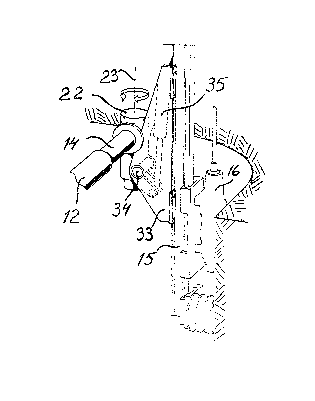
An embodiment of the invention is described below with reference to theaccompanying drawings in which fig 1 shows a side view of a drill rig
according to the invention. Fig 2 shows a part of the drill rig and
indicates possibilities of movement of the feed beam. Fig 3 shows how a rock
drilling machine can be moved close to the rock surface. Fig 4 shows a
longitudinal section through the boom of the drill rig. Fig 5 is a section
according to 5-5 in ~ig 4.
bas89018

z ~3~55(~
The rock drilling rig shown in the drawings comprises a carrier 1l on which
a first elongated boom member 12 is mounted by means of a universal joint
13. The first boom lllember is swingable relative to carrier 11 by means of
two hydraulic cylinders 32, only one visible in ths drawing. A second
elongated boom member 14 is guided by the first boom member for longitudinal
movement therein. A sliding bearing 28 is placed between the Eirst and
second boom members. At the rear or proximal end of first boom member 12 a
rotary motor 17 is mounted. The outgoing shaft 19 of the rotary motor is by
means of a splined coupling 29 connected with a hydraulic cylinder 18 which
can be rotated by means of the rotary motor 17. The external surface of the
hydraulic cylinder is provided with a number of longitudinal lands 25 and
intervening grooves 26. The second boom member 14 is at its rear end of its
internal surface provided with ridges 27 which extend into the grooves 26 of
the hydraulic cylinder 18. In this way turning of hydraulic cylinder 18 is
transferred to second boom member 14 independent of the position of the
second boom member along the hydraulic cylinder. A plastic sheet 30 is
positioned over ridges 27 to form a bearing between hydraulic cylinder 18
and second boom member 14. A piston 31 with a piston rod 20, having a
longitudinal axis 21, are movable along the hydraulic cylinder 18 by means
of hydraulic fluid entered into the hydraulic cyllnder on either side of the
piston 31. Piston rod 20 is connected with second boom member 14 so that
movement of piston 31 causes relative longitudinal movement between the
first and second boom members 12,14.
At the front or distal end of second boom member 14 a boom head 24
comprising a turning motor 22 is mounted. This turning motor makes it
possible to turn the boom head about its axis 23 in addition to the
movements made possible by the second boom member. A holder 33 for the feed
beam 15 is pivotable about a pivot 34 by means of a hydraulic cylinder 35.
Feed beam 15 is displaceable in holder 33 by hydraulic cylinder 36. A rock
drilling machine 16 is movable along feed beam 15 in a conventional way.
bas89018
.. . . . .. ... . . .. . . ... ~. .. . . , .. ~,.. ....... ......... .

Representative Drawing
A single figure which represents the drawing illustrating the invention.
Administrative Status

2024-08-01:As part of the Next Generation Patents (NGP) transition, the Canadian Patents Database (CPD) now contains a more detailed Event History, which replicates the Event Log of our new back-office solution.

Please note that "Inactive:" events refers to events no longer in use in our new back-office solution.

For a clearer understanding of the status of the application/patent presented on this page, the site Disclaimer , as well as the definitions for Patent , Event History , Maintenance Fee  and Payment History  should be consulted.

Event History

Description Date
Inactive: IPC from MCD 2006-03-11
Application Not Reinstated by Deadline 2002-02-28
Inactive: Dead - No reply to s.30(2) Rules requisition 2002-02-28
Deemed Abandoned - Failure to Respond to Maintenance Fee Notice 2001-12-05
Inactive: Abandoned - No reply to s.30(2) Rules requisition 2001-02-28
Inactive: S.30(2) Rules - Examiner requisition 2000-10-31
Letter Sent 1997-09-04
Inactive: Status info is complete as of Log entry date 1997-08-28
Inactive: Application prosecuted on TS as of Log entry date 1997-08-28
Request for Examination Requirements Determined Compliant 1997-08-12
All Requirements for Examination Determined Compliant 1997-08-12
Application Published (Open to Public Inspection) 1991-06-21

Abandonment History

Abandonment Date Reason Reinstatement Date
2001-12-05

Maintenance Fee

The last payment was received on 2000-11-14

Note : If the full payment has not been received on or before the date indicated, a further fee may be required which may be one of the following

  • the reinstatement fee;
  • the late payment fee; or
  • additional fee to reverse deemed expiry.

Patent fees are adjusted on the 1st of January every year. The amounts above are the current amounts if received by December 31 of the current year.
Please refer to the CIPO Patent Fees web page to see all current fee amounts.

Fee History

Fee Type Anniversary Year Due Date Paid Date
Request for examination - standard 1997-08-12
MF (application, 7th anniv.) - standard 07 1997-12-05 1997-11-26
MF (application, 8th anniv.) - standard 08 1998-12-07 1998-11-17
MF (application, 9th anniv.) - standard 09 1999-12-06 1999-11-17
MF (application, 10th anniv.) - standard 10 2000-12-05 2000-11-14
Owners on Record

Note: Records showing the ownership history in alphabetical order.

Current Owners on Record
ATLAS COPCO CONSTRUCTION AND MINING TECHNIQUE AB
Past Owners on Record
SVEN ERIKSSON
Past Owners that do not appear in the "Owners on Record" listing will appear in other documentation within the application.
Documents

To view selected files, please enter reCAPTCHA code :


To view images, click a link in the Document Description column. To download the documents, select one or more checkboxes in the first column and then click the "Download Selected in PDF format (Zip Archive)" or the "Download Selected as Single PDF" button.

List of published and non-published patent-specific documents on the CPD .

If you have any difficulty accessing content, you can call the Client Service Centre at 1-866-997-1936 or send them an e-mail at CIPO Client Service Centre.


Document
Description 
Date
(yyyy-mm-dd) 
Number of pages   Size of Image (KB) 
Claims 1994-03-12 1 36
Drawings 1994-03-12 2 77
Abstract 1994-03-12 1 12
Description 1994-03-12 2 86
Representative drawing 1999-07-08 1 11
Reminder - Request for Examination 1997-08-04 1 117
Acknowledgement of Request for Examination 1997-09-03 1 178
Courtesy - Abandonment Letter (R30(2)) 2001-05-08 1 171
Courtesy - Abandonment Letter (Maintenance Fee) 2002-01-01 1 182
Fees 1996-11-21 1 81
Fees 1995-11-23 1 78
Fees 1994-11-24 2 126
Fees 1993-11-25 1 55
Fees 1992-10-19 1 43