Sélection de la langue

Search

Sommaire du brevet 2031559 

Énoncé de désistement de responsabilité concernant l'information provenant de tiers

Une partie des informations de ce site Web a été fournie par des sources externes. Le gouvernement du Canada n'assume aucune responsabilité concernant la précision, l'actualité ou la fiabilité des informations fournies par les sources externes. Les utilisateurs qui désirent employer cette information devraient consulter directement la source des informations. Le contenu fourni par les sources externes n'est pas assujetti aux exigences sur les langues officielles, la protection des renseignements personnels et l'accessibilité.

Disponibilité de l'Abrégé et des Revendications

L'apparition de différences dans le texte et l'image des Revendications et de l'Abrégé dépend du moment auquel le document est publié. Les textes des Revendications et de l'Abrégé sont affichés :

  • lorsque la demande peut être examinée par le public;
  • lorsque le brevet est émis (délivrance).
(12) Demande de brevet: (11) CA 2031559
(54) Titre français: APPAREIL DE FORAGE DE ROCHES
(54) Titre anglais: ROCK DRILLING RIG
Statut: Réputée abandonnée et au-delà du délai pour le rétablissement - en attente de la réponse à l’avis de communication rejetée
Données bibliographiques
(51) Classification internationale des brevets (CIB):
  • E21B 19/08 (2006.01)
  • E21B 07/02 (2006.01)
(72) Inventeurs :
  • ERIKSSON, SVEN (Suède)
(73) Titulaires :
  • ATLAS COPCO CONSTRUCTION AND MINING TECHNIQUE AB
(71) Demandeurs :
  • ATLAS COPCO CONSTRUCTION AND MINING TECHNIQUE AB (Suède)
(74) Agent: SMART & BIGGAR LP
(74) Co-agent:
(45) Délivré:
(22) Date de dépôt: 1990-12-05
(41) Mise à la disponibilité du public: 1991-06-21
Requête d'examen: 1997-08-12
Licence disponible: S.O.
Cédé au domaine public: S.O.
(25) Langue des documents déposés: Anglais

Traité de coopération en matière de brevets (PCT): Non

(30) Données de priorité de la demande:
Numéro de la demande Pays / territoire Date
8904273-3 (Suède) 1989-12-20

Abrégés

Abrégé anglais


Abstract:
A rock drilling rig comprising a first boom member (12) connected to a
carrier (11) by a universal joint (13) and a second boom member (14) being
longitudinally displaceable relative to the first boom member by a hydraulic
cylinder (18) inside the second boom member. The external surface of the
hydraulic cylinder is provided with lands (25) and intervening grooves (26)
into which ridges (27) on second boom member (14) extend. A rotary motor
(17) at the rear end of first boom member (12) rotates the second boom
member by rotating the hydraulic cylinder.

Revendications

Note : Les revendications sont présentées dans la langue officielle dans laquelle elles ont été soumises.


Claims:
1. A rock drilling rig comprising a carrier (11), a first elongated
boom member (12), a universal joint (13) connecting said first boom member
to said carrier, a second elongated boom member (14) guided by said first
boom member for longitudinal movement relative thereto, a feed beam (15)
pivotally connected to said second boom member and a rock drilling machine
(16) moveable along said feed beam, c h a r a c t e r i z e d by a rotary
motor (17) in said first boom member (12), a hydraulic cylinder (18)
connected to an outgoing shaft (19) of said rotary motor, a piston rod (20)
of said hydraulic cylinder being connected to said second boom member (14)
to cause relative longitudinal movement between said first and second boom
members, said second boom member being coupled to said hydraulic cylinder
such that the second boom member is turnable about its longitudinal axis
(21) by said hydraulic cylinder.
2. A rock drilling rig according to claim 1, c h a r a c t e r i z e d
in that said feed beam (15) is pivotally connected to a boom head (24) being
mounted on said second boom member (14) and having an axis (23) being
perpendicular to the longitudinal axis (21) of said second boom member (14).
3. A rock drilling rig according to claim 2, c h a r a c t e r i z e d
in that said boom head (24) comprises a turning motor (22) by means of which
the boom head is turnable about its axis (23).
4. A rock drilling rig according to any one of the preceding claims,
c h a r a c t e r i z e d in that the external surface of said hydraulic
cylinder (18) is provided with a number of longitudinal lands (25) and
intervening grooves (26) and that the internal surface of said second boom
member (14) is provided with ridges (27) for cooperation with said grooves.

Description

Note : Les descriptions sont présentées dans la langue officielle dans laquelle elles ont été soumises.

1 2~3~
Rock drilling rlg
The present invention relates to a rock drilling rig and in particular to a
r;g having an extension boom.
In prior art drill rigs it has been common practice to guide the extension
part of the boom such that relative rotation between the two boom parts
cannot occur. In applications with rotation of the boom head about the
longitudinal axis of the boom one has used a rotary motor at the distal end
of the boom. A drawback with such an arrangement is that the weight at the
distal end of the boom beconmes rather high. As a consequence the boom and
the drill rig must be made stronger and heavier than otherwise. Furthermore,
the front end becomes quite big if one wants to have further possibilities
of manoeuvering the feed beam of the rig relative to the surrounding rock.
The present invention, which is defined in the subse~uent claims, aims at
providing a rock drilling rig with an extension boom where the extension
part of the boom is rotatable about the longitudinal axis of the boom by
means of a motor positioned at the proximal end of the boom. This gives the
advantage of having the weight of the rotary motor near the carrier so that
the boom does not have to be heavy in order to be sufficiently stiff.
Another advantage is that the rotary motor does not interfere with other
manoeuvering means for the feed beam which sometimes are desirable. An
important advantage with the invention is that the extension and rotation
movement of the boom can be guided in a common bearing arrangement which
al.lows savings of weight and cost. All sensitive bearings for extension and
rotation can with this invention be easily sealed off with a simple and
reliable circular sealing which will significankly increase service life
and decrease maintenance costs of the boom.
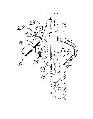
An embodiment of the invention is described below with reference to theaccompanying drawings in which fig 1 shows a side view of a drill rig
according to the invention. Fig 2 shows a part of the drill rig and
indicates possibilities of movement of the feed beam. Fig 3 shows how a rock
drilling machine can be moved close to the rock surface. Fig 4 shows a
longitudinal section through the boom of the drill rig. Fig 5 is a section
according to 5-5 in ~ig 4.
bas89018

z ~3~55(~
The rock drilling rig shown in the drawings comprises a carrier 1l on which
a first elongated boom member 12 is mounted by means of a universal joint
13. The first boom lllember is swingable relative to carrier 11 by means of
two hydraulic cylinders 32, only one visible in ths drawing. A second
elongated boom member 14 is guided by the first boom member for longitudinal
movement therein. A sliding bearing 28 is placed between the Eirst and
second boom members. At the rear or proximal end of first boom member 12 a
rotary motor 17 is mounted. The outgoing shaft 19 of the rotary motor is by
means of a splined coupling 29 connected with a hydraulic cylinder 18 which
can be rotated by means of the rotary motor 17. The external surface of the
hydraulic cylinder is provided with a number of longitudinal lands 25 and
intervening grooves 26. The second boom member 14 is at its rear end of its
internal surface provided with ridges 27 which extend into the grooves 26 of
the hydraulic cylinder 18. In this way turning of hydraulic cylinder 18 is
transferred to second boom member 14 independent of the position of the
second boom member along the hydraulic cylinder. A plastic sheet 30 is
positioned over ridges 27 to form a bearing between hydraulic cylinder 18
and second boom member 14. A piston 31 with a piston rod 20, having a
longitudinal axis 21, are movable along the hydraulic cylinder 18 by means
of hydraulic fluid entered into the hydraulic cyllnder on either side of the
piston 31. Piston rod 20 is connected with second boom member 14 so that
movement of piston 31 causes relative longitudinal movement between the
first and second boom members 12,14.
At the front or distal end of second boom member 14 a boom head 24
comprising a turning motor 22 is mounted. This turning motor makes it
possible to turn the boom head about its axis 23 in addition to the
movements made possible by the second boom member. A holder 33 for the feed
beam 15 is pivotable about a pivot 34 by means of a hydraulic cylinder 35.
Feed beam 15 is displaceable in holder 33 by hydraulic cylinder 36. A rock
drilling machine 16 is movable along feed beam 15 in a conventional way.
bas89018
.. . . . .. ... . . .. . . ... ~. .. . . , .. ~,.. ....... ......... .

Dessin représentatif
Une figure unique qui représente un dessin illustrant l'invention.
États administratifs

2024-08-01 : Dans le cadre de la transition vers les Brevets de nouvelle génération (BNG), la base de données sur les brevets canadiens (BDBC) contient désormais un Historique d'événement plus détaillé, qui reproduit le Journal des événements de notre nouvelle solution interne.

Veuillez noter que les événements débutant par « Inactive : » se réfèrent à des événements qui ne sont plus utilisés dans notre nouvelle solution interne.

Pour une meilleure compréhension de l'état de la demande ou brevet qui figure sur cette page, la rubrique Mise en garde , et les descriptions de Brevet , Historique d'événement , Taxes périodiques et Historique des paiements devraient être consultées.

Historique d'événement

Description Date
Inactive : CIB de MCD 2006-03-11
Demande non rétablie avant l'échéance 2002-02-28
Inactive : Morte - Aucune rép. dem. par.30(2) Règles 2002-02-28
Réputée abandonnée - omission de répondre à un avis sur les taxes pour le maintien en état 2001-12-05
Inactive : Abandon. - Aucune rép dem par.30(2) Règles 2001-02-28
Inactive : Dem. de l'examinateur par.30(2) Règles 2000-10-31
Lettre envoyée 1997-09-04
Inactive : Renseign. sur l'état - Complets dès date d'ent. journ. 1997-08-28
Inactive : Dem. traitée sur TS dès date d'ent. journal 1997-08-28
Exigences pour une requête d'examen - jugée conforme 1997-08-12
Toutes les exigences pour l'examen - jugée conforme 1997-08-12
Demande publiée (accessible au public) 1991-06-21

Historique d'abandonnement

Date d'abandonnement Raison Date de rétablissement
2001-12-05

Taxes périodiques

Le dernier paiement a été reçu le 2000-11-14

Avis : Si le paiement en totalité n'a pas été reçu au plus tard à la date indiquée, une taxe supplémentaire peut être imposée, soit une des taxes suivantes :

  • taxe de rétablissement ;
  • taxe pour paiement en souffrance ; ou
  • taxe additionnelle pour le renversement d'une péremption réputée.

Les taxes sur les brevets sont ajustées au 1er janvier de chaque année. Les montants ci-dessus sont les montants actuels s'ils sont reçus au plus tard le 31 décembre de l'année en cours.
Veuillez vous référer à la page web des taxes sur les brevets de l'OPIC pour voir tous les montants actuels des taxes.

Historique des taxes

Type de taxes Anniversaire Échéance Date payée
Requête d'examen - générale 1997-08-12
TM (demande, 7e anniv.) - générale 07 1997-12-05 1997-11-26
TM (demande, 8e anniv.) - générale 08 1998-12-07 1998-11-17
TM (demande, 9e anniv.) - générale 09 1999-12-06 1999-11-17
TM (demande, 10e anniv.) - générale 10 2000-12-05 2000-11-14
Titulaires au dossier

Les titulaires actuels et antérieures au dossier sont affichés en ordre alphabétique.

Titulaires actuels au dossier
ATLAS COPCO CONSTRUCTION AND MINING TECHNIQUE AB
Titulaires antérieures au dossier
SVEN ERIKSSON
Les propriétaires antérieurs qui ne figurent pas dans la liste des « Propriétaires au dossier » apparaîtront dans d'autres documents au dossier.
Documents

Pour visionner les fichiers sélectionnés, entrer le code reCAPTCHA :


Pour visualiser une image, cliquer sur un lien dans la colonne description du document. Pour télécharger l'image (les images), cliquer l'une ou plusieurs cases à cocher dans la première colonne et ensuite cliquer sur le bouton "Télécharger sélection en format PDF (archive Zip)" ou le bouton "Télécharger sélection (en un fichier PDF fusionné)".

Liste des documents de brevet publiés et non publiés sur la BDBC .

Si vous avez des difficultés à accéder au contenu, veuillez communiquer avec le Centre de services à la clientèle au 1-866-997-1936, ou envoyer un courriel au Centre de service à la clientèle de l'OPIC.


Description du
Document 
Date
(aaaa-mm-jj) 
Nombre de pages   Taille de l'image (Ko) 
Revendications 1994-03-12 1 36
Dessins 1994-03-12 2 77
Abrégé 1994-03-12 1 12
Description 1994-03-12 2 86
Dessin représentatif 1999-07-08 1 11
Rappel - requête d'examen 1997-08-04 1 117
Accusé de réception de la requête d'examen 1997-09-03 1 178
Courtoisie - Lettre d'abandon (R30(2)) 2001-05-08 1 171
Courtoisie - Lettre d'abandon (taxe de maintien en état) 2002-01-01 1 182
Taxes 1996-11-21 1 81
Taxes 1995-11-23 1 78
Taxes 1994-11-24 2 126
Taxes 1993-11-25 1 55
Taxes 1992-10-19 1 43