Note: Descriptions are shown in the official language in which they were submitted.
2~77~
HCI 023 P2 -1-
DRYER-F~SE~ APPARATUS AND METHOD FOR HIGH SPEED
ELECTROPHOTO~APHIC PRINTING DEVICE
Field of the Invention
The present invention pertains to a high speed
electrophotographic printing press and specifically to a
dryer-fuser apparatus therefor which is utilized to
evaporate toner carrier liquid from and fuse color-
imparting toner solids particles to a travelling web or
the like after the desired image has been transferred from
an electrophotographic printing cylinder to the web.
Backqround of the Invention
Electrophotographic printing is well known and
has been widely refined. For example, today, almost every
o~fice and indeed some homes have electrophotographic
copiers. The industry has grown to the point where it is
now a highly competitive multi-billion dollar industry.
In most instances, these home and office copiers are
capable of providing only about a few copies per minute.
In electrophotography, images are
photoelectrically formed on a photoconductive layer
mounted on a conductive base. Liquid or dry developer or
toner mixtures may be used to develop the requisite image.
Liquid toner dispersions for use in the process
are formed by dispersin~ dyes or pigments and natural or
synthetic resin materials in a low dielectric constant
carrier liquid. Charge control agents are added to the
liquid toner dispersions to aid in charging the pigment
2~3~ ~7~
HCI 023 P2 -2-
and dye particles to the requisite polarity for proper
image formation on the desired substrate.
The photoconductive layer is sensitized by
electrical charging whereby electrical charges are
uniformly distributed over the surface. The
photoconductive layer is then exposed by projecting or
alternatively by writing over the surface with a laser,
L.E.D., or the like. The electrical charges on the
photoconductive layer are conducted away from the areas
exposed to light with an electrostatic charge remaining in
the image area. The charged pigment and/or dye particles
from the liquid toner dispersion contact and adhere to the
image areas of the photoconductive layer. The image is
then transferred to the desired substrate, such as a
travelling web of paper or the like.
In contrast to office and home copiers, high
speed electrophotographic printing presses are being
developed wherein successive images are rapidly formed on
the photoconductive medium for rapid transfer to carrier
sheets or the like travelling at ~peeds of greater than
- lO0 ft./min. and even at speeds of from 300-500 ft./min.
These high speed presses are capable of delivering ~0
million copies per month with web or copy widths being on
the order of 20 inches or greater.
In a high speed printing press, it is necessary
that the image, after application of toner, be thoroughly
fixed and dried prior to later (downstream) operations
such as punching, perforating, rewinding, folding and/or
sheeting in order that the final printed production is of
.. . . . . . . . . . . .
~317'~
HCI 023 P2 -3-
requisite quality and press parts remain clean and free of
toner which can mark the web. Furthermore, to dry and
fuse a variety of different color toners efficiently, it
is highly desirable to heat the travelling web, therefore
volatilizing the dielectric carrier liquid and fusing the
pigment and/or dye particles and associated synthetic
resin binder to the web in such manner that image smearing
is inhibited by minimizing contact of the travelling web
surfaces with conveyor rollers and the like.
Further, due to the heat requirements of the
drying process, and the attendant energy costs associated
with same, it is highly desirable to provide a dryer-
fuser apparatus that may successfully operate at high
speed, while minimizing the energy input requirements for
the heating process.
Due to the flammable nature of the dielectric
carrier liquid utilized in ~uch electrophoto~raphic
processes, it is highly desirable to provide a drying
apparatus which maintains the drying atmosphere at a level
that is substantially less than the lower flammability
level of the carrier liquid. That is, at certain levels,
the volatilized dielectric carrier liquid can provide a
source of considerable danger in that in the presence of
an external flame or spark the volatiles may ignite. For
this reason, it is desirable to provide a dryer-fuser
apparatus whereby fresh make-up air can be readily
admitted to the drying zone so as to aid in maintaining
the carrier liquidJatmospheric gas content well below that
of the lower flammability level of the carrier liquid.
~03~ i~ 7~
HCI 023 P2 -4-
Further, it is desirable to provide a system to
monitor the concentration of volatile carrier liquid in
the dryer to control the rate at which the volatile gas
containing atmosphere is exhausted from the apparatus in
response thereto. At increasingly higher volatile levels,
it is deYirable to halt the travel of the web through the
dryer altogether.
Summary of the Invention
In accordance with the invention, a dryer-fuser
apparatus and method are provided for utili2ation in a
high speed electrophotographic printing process of the
type adapted to operate at web speeds of 100 fto/min. and
greater. More specifically, such high speed methods may
operate at speeds of 300-500 ft./min.
The travelling web is forwarded by conveyor
rolls or the like into a dryer housing that is provided
with a pair of opposed hot air supply manifolds. Each
manifold communicates with a plurality of air supply tubes
that extend transversely across the web travel direction.
The tubes are each provided with a plurality of apertures
through which hot air passes to effect drying of the web.
As the web travels through the dryer, it is interposed
between the air supply tubes and held under tension by the
rolls. The velocity of the hot air emanating from the
tubes provides an air cushion for the web's travel through
the aryer so that substantially no or little contact of
the web is made with the air supply tubes during web
travel through the dryer~ As such, the wPb is suspended
2 ~ r~
HCI 023 P2 -5-
in the air cushion. Volatiles and hot air from the dryer
housing are vented to a conduit in communication with a
catalytic converter device.
As is known in the art, such catalytic converter
devices comprise a ixed bed catalyst that supports
exothermic degradation of the volatile organic compounds.
The hot effluent gases emanating from the catalytic
converter may then be either vented to exhaust or a
portion thereof may be recycled to the air supply
manifolds to provide heat for the drying process. The use
of recycled heat from the catalytic oxidation of carrier
liquid to dry and fix an image transferred to a copy sheet
is nott in and of itself, new. For example, in
conjunction with home and office type copiers, U.S. Patent
4,538,899 discloses ~uch methods and a device therefor~
In accordance with the invention, a portion of
the recycled heat from the catalytic converter is returned
to an upstream heat exchanger to heat the volatile
materials and hot air vented from the dryer housing. In
such manner, the volatiles and hot exhaust air emanating
from the dryer housing may be preheated prior to their
passage through the catalytic converter.
During system start up and for those times in
which auxi:liary heating means are required, an electrical
resistance heater or the like may be used to supply heat
to the dryer. A recycle bypass damper is also provided to
regulate the amount of recycled heat from the catalytic
converter that is recycled to the dryer.
.. . ... ..
177~
HCI 023 P2 -6-
A make-up air damper, in communication with a
source of fresh make-up air, regulates the amount of fresh
make-up air that is forwarded to the heater. The amount
of make-up air admitted to the dryer is controlled by a
pressure monitoring d~vice that measures the pressure
within the dryer.
An active flame sensor monitors the lower
flammability level of the atmosphere within the dryer. In
response to this sensor, the speed of the dryer exhaust
~an is controlled so that the atmosphere is preferably
maintained at or below about 25% of the lower flammability
level ~L.F.L.) for the particular carrier liquid that is
used. At higher LFLs, the drive responsible for advancing
the web through the dryer is stopped and an audible alarm
is actuated.
The invention will be further described in
conjunction with the following detailed description and
the appended drawings.
In the drawings:
Fig. l is a schematic diagram showing the
overall layout of components needed to form and develop
the required image on the photoconductive cylinder surface
and to transfer the developed image to a travelling web;
Fig. 2 is a schematic diagram of the dryer-
fuser apparatus of the present invention; and
Fig. 3 is a control diagram showing the
particular means for sensing and controlling various
aspects of the dryer-fuser.
.. . . . . , . . . . , ~ . . . . . .
2~3:~7rt~:i
HCI 023 P2 -7-
Turning first to the drawings and to Fig. 1
thereof, this view shows the overall organization of a
typical photoconductive cylinder and associated mechanisms
for formation of the latent electrostatic image, and
subsequent image formation on the cylinder surface. A
rotatable photoconductive drum 50, typically As2S~, SeTe
or others, rotates in a counterclockwise direction as
indicated by the arrow shown on cylinder 50 in Fig. l.
Special systems are arranged sequentially around drum 50
as shown in Fig. l, to accomplish the desired formation
and trans~er of images onto web w. These systems include
a high intensity charging apparatus 52, exposing-
discharging (or imaging) apparatus 54, developing
apparatus 55, transfer apparatus 56 and cleaning apparatus
58. These assure that the drum surface is charged,
exposed, discharged and cleared of residual toner, while
the developed images are continually transferred to the
web material w.
Charging apparatus 52 comprises a plurality of
corona discharge devices comprising corona discharge wires
disposed within appropriately shaped shielded members with
each wire and associated shield member forming a separate
focusing chamber. The charge imparted by the coronas to
the photoconductive cylinder is on the order of at least
~1000 volts d.c., preferably between +1000 and +1450
volts. These corona assemblies extend across the drum
surface 51 and along an arc closely parallel to surface
51. In a successful embodiment using a drum having a 33-
inch circumference (thus 10.504-inch diameter), the
... . . . . . ... . ..
~3~7'7~
HCI 023 P2 -8-
arcuate length of the charging unit is about 4.5 inches or
somewhat greater than l/8th of the drum circumference.
Proceeding counterclockwise around the drum (as
viewed in Fig. l), there is a charge potential sensor 65
(an electrometer) which senses the voltage at the surface
51 and provides a continuous feedback signal to a charging
power supply (not shown) to thereby adjust the charge
level of the photoconductor surface 51 regardless of
variations due, for example, to irregularities in the
power supply or changes in the peripheral velocity of drum
50.
Di~ital imaging device 54, in the form of
relatively high intensity L.E.D. double row array 70 is
mounted to extend transversely of the rotating drum
surface 51. Each L.E.D. is individually driven from a
corresponding driver amplified circuit, details of which
need not be described herein. Light emitted from the
L.E.D.s is in the range of 655-685 nm through a Selfoc
lens 72 onto the drum surface 51 in a dot ~ize of 0.0033
inch diameter. In one successful embodiment, there are a
total of 6144 L.E.D.s in the array, divided between two
rows which are spaced apart in a direction along the
circumference of the ~urface by 0.010 inch and all fixed
to a liquid cooled base block (not shown). The space
between adjacent L.E.D.s in the same row is 0.0033 inch
horizontally or transverse to the drum surface and the
L.E.D. arrays in the two rows are offset horizontally by
the same dimension, thus the L.E.D.s can cooperate to
discharge a continuous series of dots across drum surface
. . ... . . . . . . . . . ..
2~3~775
HCI 023 P2 -9-
51 at a resolution of 300 dots/inch.
Light from the L.E.D.s operates to discharge the
background or non-image areas of the passing drum surface
to a substantially lower potential, for example, in the
order of +100 to ~300 volts d.c. by exposing individual
dot areas to radiation at a predetermined frequency, as
mentioned, whereby the remaining or image areas comprise a
latent electrostatic image of the printed portions of the
form.
Although the use of an L.E.D. arrangement has
been depicted herein as providing for the requisite image,
other conventional means for forming the requisite image
may also be utilized. For instance, laser printing and
conventional exposure methods such as reflection from high
contrast originals and projection through transparencies
and the like may also be utilized, although they are not
preferred.
The latent electrostatic image then is carried,
as the drum rotates, past developing station 55 where it
is subjected to the action of a special high speed liquid
toner developer of the type comprising a dielectric
carrier li~uid material, such as the Isopar series of
hydrocarbons, resinous binder particles, and color-
imparting dye and/or pigment particles. As is known in
the art, the desired charge may be chemically supplied to
the resin-pigment/dye particles by utilization of well-
known charge control agents such as lecithin and alkylated
vinylpyrrolidone materials. In the embodiment shown, drum
50 comprises an As2Se3 photoconductive layer to which
2Q3~77~
HCI 023 P2 -10-
charge coronas 52 impart a positive charge. The toner
particles are accordingly provided with a negative charge
in the range of about 60 to 75 picamhos/cm.
The developing station 55 comprise~ a shoe
member 80, which also functions as a developer electrode
(which is electrically insulated from drum 50 and extends
transver~ely across drum surface 51). The face of shoe
member 80 is curved to conform to a section of drum
surface 51 and, in a successful embodiment, has a length,
along the arcuate face, of about 7 inches, ~lightly less
than 1/4 of the circumference of drum surface 51, and
which is closely fitted to the moving drum surface, for
example, at a spacing of about 500 microns (O.Q20 inch~.
Shoe 80 is divided into first and second cavities 82, 83
(see Fig. 5) through each of which is circulated liquid
toner dispersion from a liquid toner dispersion supply and
replenishment system.
Liquid toner dispersion is supplied to developer
electrode 80 through conduit 10 via action of pump 12 and
associated adjustable flow valve 14. The toner dispersion
is fed to manifold 16 and then through inlet supply pipes
18~a-d). Polyurethane tire~ 20, 22 are journalled in the
sidewalls of develcper electrode hou~ing and ride upon
anodized rims that are circumferentially disposed about
periphery of drum 50. A direct current source, indicated
generally by the reference numeral 24, is provided to
apply bias through conductor 26 to the electrode 80.
A toner sump 28 is provided to surround
electrode 80 and is provided with a sump return line 30 to
2~3~7~
HCI 023 P2 -11-
return spent toner dispersion to a liquid toner supply
system ~not shown).
The developer shoe 80 functions as an electrode
which is maintained at a potential on the order of about
+200 to 600 volts d.c. Thus, the negatively charged toner
particles are introduced into the shoe cavities and are
dispersed among electrical fields between: 1) the image
areas and the developer electrode on the one hand and
between 2) the background and the developer electrode on
the other hand. Typically, the electrical fields are the
result of difference in potential: a) between the images
areas (+1000 to 1450 volts) and the developer electrode
(+200 to +600 volts) which causes the negatively charged
toner particles to deposit on the image areas, and b) the
field existing between the background areas (+100 to +300
volts~ and the developer electrode (+200 to +600 volts)
which later field causes the toner particles to migrate
away from the background areas to the developer shoe. The
result is a highly distinctive contrast between image and
background areas, with good color coverage being provided
in the solid image areas. The tendency of toner particles
to build up on the developer shoe or electrode is overcome
by the circulation of the liquid toner therethrough at
rates on the order of about 7.57 to 37.85 liters/min. (2
to 10 gallonJmin.) back to the toner refreshing system.
As the drum surface passes from the developer
shoe, a reverse rotating metering roll 32, spaced parallel
to the drum surface by about .002-.003 in., acts to shear
away any loosely attracted toner in the image areas, and
203~7'~5
HCI 023 P2 -12-
also to reduce the amount of volatile carrier liquid
carried by the drum and any loose toner particles which
might have migrated into the background areas. The
metering role has applied to it a bias potential on the
order of about +200 to +600 volts d.c. from d.c. power
source 34 and conductor 36, varied according to web
velocity. Reverse roll 32 is driven via drive roller 38
with drive being transmitted through belt or chain member
40. A position sensor 42 is provided to sense the
position of roll 32 as shall be explained in greater
detail hereinafter.
Proceeding further in the counterclockwise
direction with regard to Fig. l, there is shown a transfer
apparatus 56 adapted to effect transfer of the image from
the photoconductive surface to a travelling web w of paper
or the like. A pair of idler rollers 90a, b guide web
onto the "3 o'clock" position of drum 50 and behind the
web path at this location is a transfer coratron 92. The
web is driven at a speed equal to the velocity of drum
surface 51 to minimize distortion of the developed image
on the surface 51. The positioning of rollers 90a, b is
such that the width ~top to bottom) of the transverse band
95 of web-drum surface contact is about 0.5 inch centered
on the radius of the drum which intersects the coratron
92.
The shape of the transfer coratron ~hield 96,
and the location of the axis of the tungsten wire and
shield 96 is such as to focus the ion "~pray" from the
coratron onto the web-drum contact band on the reverse
2 ~ 3 ~ 7 rl 5
HCI 023 P2 -13-
side of web w. The transfer coratron 92 has applied to it
a voltage in the range o~ +6600 to +8000 volts d.c., and
the distance between the coratron wire 93 and the surface
of web w is in the order of about 0.25-0.35 inch -
preferably .317 inch. This results in a transfer
efficiency of at least 95% of the solids particles of the
liquid toner dispersion. Both solid toner particles and
liquid carrier material are transferred to the web.
The web path continues into a fuser and dryer
apparatus 100 (Fig. 2), wherein the carrier liquid is
evaporated from the web material and the toner particles
are fused thereto as shall be explained in greater detail
hereinafter. Proceeding further in the clockwise
direction with respect to Fig. 1, a cleaning apparatus 58
is utilized to remove all toner particles and carrier
liquid from the drum sur~ace 51 and erase lamp lll is
arranged to flood surface 51 with either blue or white
light emanating from a fluorescent tube. Satisfactory
cleaning results have been achieved with blue fluorescent
tubes emitting predominantly at about 440 nm and with
white fluorescent tubes emitting predominantly at 400,
440, 550 and 575 nm.
The foam roller 60 is of a polyurethane open
cell construction and is fixed to a power driven shaft
which is rotated in the opposite direction to drum surface
motion, as indicated by the arrows in Fig. l, so as to
compress against and scrub the surface 51. The
compression/expansion of the open cell foam during this
action will tend to draw liquid carrier material and any
~31~
HCI 023 P2 -14-
included toner particles remaining on the surface 51 off
of that surface and into the cells of roller 60.
A cleaning blade 66, comprising a tough, but
flexible, polyurethane wiper blade is mounted with its
edge extending forward and into contact with surface 51,
just beyond foam roller 60. Blade 66 acts to wipe the
drum surface S1 dry, since the photoconductor surface must
be dry when it reaches the charging stationO
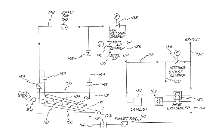
Turning now to Fig. 2, it can be seen that web,
w, is admitted into dryer-fuser apparatus 100, comprising
housing member 112. The web is conveyed through the
dryer-fuser by use of roller 90b and drive roller 102. As
shown, the web is guided downwardly along an inclined path
through the dryer-fuser. The dryer is designed to fuse
toner on both sides of the web. In perfecting printing
both sides of the web become "wet". Roller 90b has a
surface made of expanded metal which presents a multitude
of sharp points to support the web. The toned image only
touches the this roll at discrete points each of minuscule
size ~or area) so the image is not disrupted. This is
important in minimizing disturbance or distortion of the
desired image. Air supply manifolds 104, 106 are provided
with each carrying air supply tubes 10~, 110 which tubes
extend transversely across the surfaces of the web with
the lower and upper array of tubes being offset from the
other. As can be seen, the web is interposed between the
surfaces of the tubes 108, 110 which are provided with a
multiplicity of apertures therein to blow hot air onto the
web from opposite sides thereof.
. . . .. . . . . . .
2a~3 ~r~/~5
HCI 023 P2 -15-
In accordance with the invention, the flow rate
of hot air emanating from the air supply tube~ 108, 110 is
such as to provide an air cushion to cushion the web as it
travels through the heater. In such manner, the web
essentially floats through the heater while making little
or no contact with surface portions thereof. Again, this
tends to minimize smearing and image distortion that may
otherwise occur during heating processes wherein the
travelling web is contacted with roller and/or heater
surfaces in the heater proper, Heated air at a
temperature on the order of around 250CF is ejected at
5,000 to 10,000 fpm from the air supply tubes as the
surfaces of the moving web are transported at velocities
in the range of from 100-500 ft./min. The hot air
velocity is such that the web is kept spaced away from the
nozzle arrays and follows a somewhat sinuous path between
the manifolds 104, 106.
The hot air performs two functions. First, it
volatilizes the liquid carrier material that has been
applied to the travelling web. Secondly, it heats the web
causing the solids toner particles to fuse onto the
desired place on the web. In a typical operation, this
requires sufficient heat transfer to remove and vaporize
carrier liquid at rates of about 850g/min. and higher.
Volatiles and hot air in housing 112 are vented through
conduit 114 and filter 116 by the action of downstream
exhaust fan 118 thereon. The vented volat~les-hot exhaust
air pass along conduit 11~ to heat exchanger 120, the
function of which shall be explained hereinafter.
.
2~3~7'7~
HCI 023 P2 -16-
During startup and at other times when auxiliary
heating is required, an electrical resistance heater 122
is operated to provide supplementary heat through the
conduits to supply manifolds 104, 106 through respective
S damper members 152, 154. Proceeding further in a
downstream direction, the volatiles and hot air enter
catalytic converter 124 wherein, in conventional manner,
the volatile organic materials are exothermically
converted into carbon dioxide and water whereby hot
effluent exhaust air from catalytic converter 124 is
passed to recycle line 126. A portion of the hot effluent
air from the catalytic converter is diverted into bypass
conduit 128 and heat exchanger flow line 130 whereby it
heats the vented volatiles-hot air in conduit 114 to
preheat the volatiles and exhaust air from dryer 112 prior
to admission thereof into the catalytic converter means
124. The portion of heated effluent from catalytic
converter 124 channeled through the heat exchanger is then
conducted to exhau~t port 132. A damper means or the
like, 134, is provided in the bypass conduit line 128 so
as to regulate back pressure in the system and to aid in
regulating the amount of hot effluent air from the
catalytic converter 124 that is passed through heat
exchanger 120.
As is readily apparent, a portion of the hot
effluent air from catalytic converter 124 is conducted
through recirculator conduit 126 and is returned via the
action of supply fan 150 and conduit 148 through either
damper 152 or 154 to supply hot air to the air manifolds
.
2 0 3 ~
HCI 023 P2 -17-
104, 106. This is an important part of the invention in
that, after the initial heat required for the process is
provided by resistance heater 122, the resistance heater
122 can be turned off with heat supplied to the dryer 100
being co~posed entirely of heat emanating from catalytic
converter 124 through recycle conduit lines 126 and 148.
A return line damper 136 is used to regulate the amount of
this recycled heat that is supplied to the manifolds 104,
106.
A fresh make-up air source 138 is provided in
conjunction with damper means 140 to regulate the amount
of fresh make-up air drawn by supply fan 150 through
conduit 148 through either damper 152, 154 to the
manifolds 104, 106. If desired, direct exhaust from
housing 112 may be drawn through filter 142 and conduit
144 to and through conduit 148 to recycle exhaust air
(including volatiles) to the air manifolds 104, 106. The
amount of recycled exhaust air is regulated by means of a
damper 146.
It has been found that heat from the catalytic
converter effluent air, once the system has been brought
to operate within a range of normal speeds, is sufficient
to continue the recirculation, heating and filtering of
the dryer-fuser air without the continued use of heater
122, which can then be switched off. The fuser-dryer
apparatus thus is a recuperative system which effectively
controls emissions from vaporization of the carrier liguid
and recovers the resulting heat to further the fusin~ and
drying proceYs.
2 ~ 3 ~l 7 r~ !~
HCI 023 P2 -18-
The roller 102 is chilled by internal cooling
means and serves to reduce the temperature of the web
material to approximately ambient. Downstream from this
chilled drive roll 102, a plurality of other operations
such as punching, perforating, rewinding, folding,
sheeting, etc., may be performed on the travelling web in
accordance with well-known techniques. Details of such
additional operations may be gleaned from ~.S. Patent
4,177,730, the content of which is herein incorporated by
reference.
Based upon preliminary data, typical operating
parameters of the dryer-fuser system of the invention
include a temperature on the web surface of about 250F
during travel thereof through the dryer-fuser apparatus
10Q. The temperature of the heat/exchanger output is
about 500~F.
Due to the flammable nature of the ISOPAR
carrier li~uid, it is highly desirable to perform the
heating-fusing operation in such manner that the content
of volatile material is maintained well belo~ the lower
flammability level of same. To this end, the dryer-fuser
is adapted to operate at a level of 25% of the LFL (lower
flammability level) of the carrier liquid or lower.
Variables important in maintaining such atmosphere are the
minimum flammable vapor concentration of Isopar in air,
web speed, solvent content of the traveling web, amount of
fresh make-up air admitted to the system and the amount of
return volatiles and hot air recycled to the heater
through line 14~ and damper 146.
2~3~r~7~
HCI 023 P2 -19-
One of the advantages of the use of a hot air
dryer as described and claimed herein over other dryers,
such as microwave dryers, is that a variety of different
toners may be dried. For instance, certain microwave
dryers rely upon energy at a particular wavelength.
However, in the present invention, the travelling web is
heated with heat transfer from the web to the toner being
used to fuse the toner particles.
Turning now to Fig. 3, there is shown, in block
format, a simplified control system schematic for the
apparatus. A pressure monitoring device 202, such as a
diaphragm containing pressure switch is contained within
the dryer-fuser apparatus l00. Desirably, the pressure in
the apparatus 100 is maintained at -1" Hz0. The
information from the pressure monitor 202 is forwarded to
a programmable logic controller (PLC) 250 that compares
the measured pressure with a desired set-point pressure
which, in this instance, is -1" H20. If the pressure is
less than the desired set point (i.e., too much negative
pressure in the fuser-dryer), the PLC sends an analo~
- signal to adjustably open the make-up air damper 140 to in
turn allow fresh make-up air to be supplied to the damper
members 152, 154. Conversely, if the pressure exceeds the
desired set point, the damper 140 is closed.
The opening or closing of hot air return damper
136 is similarly controlled by the PLC 250. Here, when
the printing press is running, the temperature of the web
exiting the dryer-fuser is measured by a thermocouple 204
or the like. This temperature information is supplied to
2~3~77~
HCI 023 P2 -20-
the PLC 250 wherein it is compared to a predetermined set-
point, here, for example 220F. If the indicated
temperature is greater than this desired set-point, the
PLC sends an analog signal to the adjustable air return
damper 136 to close same to prevent air from the catalytic
converter from entering the conduit 148 for recycled use
in the fuser-dryer. In contrast, if the web temperature
is below the predetermined set-point, the da~per 136 is
opened to allow recycling of the air emanating from the
catalytic converter 124.
When the printing press is not running, a
thermocouple 206 measures the temperature with the fuser-
dryer 100. This temperature information is supplied to
PLC wherein it is compared to a predetermined set-point,
for example, 350F. Again, if the measured temperature
exceeds this set point, the damper 136 is closed
preventing communication between duct sections 126, and
148. If the measured temperature is below the set-point,
the damper 136 is opened.
Temperature control of the hot-side bypass
damper 134 is also provided. A thermocouple or like
device 208 is located just upstream from the catalytic
converter 124. This temperature information is conveyed
to the PLC where it is compared to a predetermined set-
point range. Here, for example, if the measured
temperature is less than about 450~F, the PLC transmits an
analog signal to the damper controller to close the bypass
damper 134 to ensure that all hot air travelling through
duct 128 is diverted through heat exchanger flow line 130.
... ..
7 7 ~
HCI 023 P2 -21-
Conversely, if the temperature information sent to PLC by
thermocouple 208 exceeds the high end of the set-point
range, for example, 550F, the bypass damper 134 is
opened, thereby ensuring that a portion of the air passing
through duct line 128 will pass directly through the
damper 134 to exhaust 132 without travel through heat
exchanger flow line 130.
Most importantly, due to the highly flammable
nature of the carrier liquid utilized in the liquid toner
dispersion formulations, a control system is provided to
monitor and regulate the percent of carrier liquid
concentration in the dryer-fuser atmosphere. To this end,
a lower flammability limit (LFL) monitor 210 is
positioned within the housing of the dryer-fuser. The
preferred monitor 210 is the Model FFA "Sensing Flame
Detection System" available from Control Instruments
Corporation, Fairfield, New Jersey. This device comprises
an active sensing flame. Flammable vapors that enter the
device are incinerated by the flame. This action results
in an increase in the BTU output of the flame which is
measured by a resistance temperature detector which is
then transmitted and indicated on a control module in
terms of the LFL. This LFL signal is then used as input
to the PLC 250. When the LFL value is greater than a
predetermined low range set-point, for example, about 18%,
the PLC sends an analog signal to a controller 212 which
regulates ~increases) the speed of the variable speed
exhaust fan 118. If the LFL value exceeds an intermediate
range set-point, for example, 25%, the PLC disconnects
.
2~3~7~
HCI 023 P2 -22-
drive 214 for the chilled roll 102, thus stopping web
travel through the dryer-fuser. An upper range LFL ~et-
point, for example, 40% or 50%, may be set whereby in
addition to actuation of the exhaust fan 118 and
disconnection of drive for chill roll 102, audible alarm
216 is signalled.
Turning briefly to Fig. l, sensor 42 monitors
the position of reverse roller 32. When the reverse
roller is not in its operative condition spaced closely
adjacent to surface 51 so as to shear excess toner carrier
liquid and solids particles from the surface, a signal is
sent to PLC 250 (Fig. 3) to disconnect drive 214 for the
chilled roll 102 to halt advancement of the web through
the dryer.
Although this invention has been described with
respect to certain preferred embodiments, it will be
appreciated that a wide variety of equivalents may be
substituted for those specific elements shown and
described herein, all without departing from the spirit
and scope of the invention as defined in the appended
claims.