Language selection

Search

Patent 2031779 Summary

Third-party information liability

Some of the information on this Web page has been provided by external sources. The Government of Canada is not responsible for the accuracy, reliability or currency of the information supplied by external sources. Users wishing to rely upon this information should consult directly with the source of the information. Content provided by external sources is not subject to official languages, privacy and accessibility requirements.

Claims and Abstract availability

Any discrepancies in the text and image of the Claims and Abstract are due to differing posting times. Text of the Claims and Abstract are posted:

  • At the time the application is open to public inspection;
  • At the time of issue of the patent (grant).
(12) Patent: (11) CA 2031779
(54) English Title: STEAM TRAP
(54) French Title: PURGEUR D'EAU DE CONDENSATION
Status: Expired
Bibliographic Data
(52) Canadian Patent Classification (CPC):
  • 137/9
(51) International Patent Classification (IPC):
  • F16T 1/04 (2006.01)
  • F16T 1/10 (2006.01)
(72) Inventors :
  • AYVAZ, OHANNES (Turkiye)
(73) Owners :
  • DOMNIK CANADA INC. (Canada)
(71) Applicants :
(74) Agent: GOWLING LAFLEUR HENDERSON LLP
(74) Associate agent:
(45) Issued: 1995-03-21
(22) Filed Date: 1990-12-07
(41) Open to Public Inspection: 1991-06-08
Examination requested: 1990-12-07
Availability of licence: N/A
(25) Language of filing: English

Patent Cooperation Treaty (PCT): No

(30) Application Priority Data:
Application No. Country/Territory Date
P3940775.6-12 Germany 1989-12-07

Abstracts

English Abstract


The invention relates to a thermally controlled steam trap with a casing
formed from two disk-like wall portions, with a diaphragm arranged
between them and which is tightly welded at its outer edge to the two
wall portions and forming with one wall portion a chamber receiving
an expansion medium, and with a closure centrally fixed to the diaphragm
and cooperating through a bore in the second wall portion with a valve
seat.

According to the invention the closure 7 is centrally connected to
the diaphragm 4 and a counterpart 15 by resistance forge welding.
In order to obtain a clean weld, the closure 7 is specially designed
for resistance forge welding (Fig.1).


Claims

Note: Claims are shown in the official language in which they were submitted.


CLAIMS 5

1. Steam trap with a casing formed from two disk-like wall portions,
with a metallic diaphragm positioned between them, tightly welded at its outer
edge to the two wall portions and forming with one wall portion a chamber
receiving the expansion medium and with a closure centrally fixed to the
diaphragm and cooperating with a valve seat through an opening in the second
wall portion, characterized in that the geometrical basic shape of the closure (7)
essentially comprises three partial bodies (11,12,14), namely a circular cylindrical
partial body (11) cooperating with the valve seal, a tapering, conical rotating
body (12) connected to the latter and a spherical portion (14) connected to the
body (12) that the diaphragm (4) is centrally provided with a depression
corresponding to the spherical portion (14), that counterpart (15) is provided
which, like the diaphragm, has a depression corresponding to the spherical
portion, and that the closure, the diaphragm and the counterpart are
interconnected by resistance forge welding.

2. Steam trap according to claim 1, characterized in that the diaphragm
(4) comprises several lamellas.

3. Steam trap according to claim 1, characterized in that the
counterpart (15) has an all-round, annular contact surface (16) for the diaphragm
(4).

4. Steam trap according to claim 3, characterized in that the closure (7)
fixes the diaphragm (4), together with the annular contact surface (16) of the
counterpart, in the vicinity of its conical rotary body (12).

5. Steam trap according to any one of claims 1 to 4, characterized in
that between the two wall portions (2,3) is provided a third, disk-like component
(18), which limited the diaphragm lift.

Description

Note: Descriptions are shown in the official language in which they were submitted.


` ~ 2 ~ 7 9

Steam Trap

The invention relates to a steam trap of the type specified in the
preamble of the main claim.

Such 8 steam trap is e.g. known from German Patent 19 17 585. The
steam trap described therein essentially comprises a chamber closed
by a diaphragm and which is filled with a medium eXpAn~lng when heat
is supplied and contracting when heat is removed and which when the
temperature changes brings about a lifting movement of the diaphragm.
A closure, which cooperates with a valve seat, is centrally arranged
on the diaphragm.

It has always been a problem to so connect the closure to the diaphragm,
optionally with the aid of a counter~art, in such a way that a permanent
tight connection is ensured and that the diaphragm is not so damaged
that its life is drastically reduced.

In a steam trap known from Cerman Patent 19 17 585, the closure i8
e.g. connected by a rivet to the diaphragm and a counterpart. The
connection procedure by rivets is disadvantageous in that leaks are
to be feared. A leak l~ads to a running out of the expansion medium
and consequently the steam trap bec~mes unusable.

Steam traps are known, e.g. from French patent 858 960, in which the
central rivet i~ additionally circumferentially welded to the diaphragm
or in the case of a mult~l~m?l~r diaphragm to the individual l~
of the diaphrag~. The c ~n~tion of rivets and welding is very compli-
cated from the production standpoint.

3U German Patent 26 30 038 discloses a steam trap of the aforementioned
type with a diaphragm comprising several lamellas, in which the closure
is centrally provided on the diaphragm side with a torus and has a
clamping dis~ (a counterpart). The clamping disk and the diaphragm
lamellas have a central bore and in the end face region thereof ad~acent
to the central bore have a complementary shape to the external circum-
ferential surface of the torus. The diaphragm lamellas are fixed between


,~r ,

2031779

-- 2 --

the closure and the clamping disk (the counterpart) and the closure,
the clamping disk and the diaphragm lamellas are firmly and tightly
welded together on their ad~acent bore edges or on the back of the
torus. However, this connection method is also relatively complicated
from the production standpoint, because several bores have to be made
either by machining, or by punching.

A basically similar fastening mode i8 known from German Patent 31 Z4 459
in which the bore has an undercut in the closure, 80 that there is
no need to deform the diaphragm in the vicinity of the welding zone.

It is common to all the known stream traps that the connection between
the closure and the diaphragm optionally formed from several 1 r
is very complicated from the production standpoint.
The problem of the invention is consequently to so improve a steam
trap of the aforementioned type, that it i8 possible to easily and
reliably connect the diaphragm and the closure, as well as a counterpart.

In the case of the aforementioned steam trap, this problem is inventively
solved by the features of the characterizing part of claim 1.

As a result of the inventive construction of the closure, the diaphragm
and the counterpart, contact surfaces are created in an ex~re -ly simple
2~ manner which are eminently suitable for a connection by resistance
forge welding.

For the preferred embodiments Or the invention are described in the
subclaims. In particular according to subclaim 4 the ring area Or
the counterpart and the approximately conical portion of the closure
secure the diaphragm between them, so that the bending stresses caused
by diaphragm lift are kept away from the welding zone, which has under-
gone a structural change.
.

According to further preferred embodiment it is also possible to provide
a disk-like component serving as a diaphragm lift limiter or stop.

,~, 203177g
-- 3 --

The invention is described in greater detail hereinafter relative to
the drawings, wherein show:

Fig.l an embodiment of an inventive steam trap.

Fig.2 a steam trap according to the invention with an additional liPt
limiting disk.

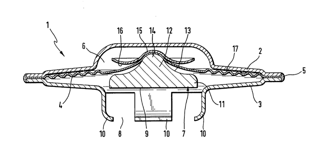
An inventive steam trap 1, as shown in Fig.l, comprises two disk-like
wall portions 2,3, between which is secured a diaphragm 4. The wall
portions 2,3 and the diaphragm 4 are welded together along their circular
circumference 5. A chamber 6, which is filled with an expansion medium,
is formed between the diaphragm 4 and the upper wall portion 2. A
closure 7 is centrally fixed to the diaphragm and cooperates by an
opening 8 in the lower wall portion 3 with a not shown valve seat.
IP the steam trap is wetted with condensed steam, which i8 cooler than
the supersaturated steam which normally travels past the steam trap,
then the expansion medium in the chamber 6 contracts, 80 that the dia-
phragm 4 and with it the closure 7 is moved into the represented posit on.
A lower bearing surface 9 of the closure 7 is then raised from the
not shown valve seat and then the condensed steam can Plow out. IP
the temperature oP the medium Plowing past the steam trap rises again,
i.e. when all the condensed steam has been let ofP and the steam trap
is only surrounded by superheated steam, then the expansion medium
~5 in the chamber 6 expands again, so that the diaphragm 4 and with it
the closure 7 is moved downwards, so that the bearing surface 9 o~
the closure 7 comes to rest on the valve seat.

The entire steam trap 1 can be fixed with re~aining springs 10 eng~F~ ng
in finger-like manner about a not shown edge oP the valve seat.

According to the invention the geometrical basic shape oP the closure
7 comprises three partial bodies. To the bearing surface 9 is initially
connected a cylindrical partial body 11, which passes into an upwardly
tapering, roughly conical rotating body 12, whose envelope curve 13

20~1779
_ 4 -

can be concave and finally this is followed by a spherical portion
14. In an area ad~acent to the closure, the diaphragm 4 is shaped
in a complimentary manner to the said spherical cup or to said spher-
ical portion. In the vicinity of the spherical portion 14, ~he closure
7 i8 connected to the diaphragm 4 and a counterpart 15 located on the
other side of the diaphragm by resistance forge welding. The counter-
part 15 has an all-round, annular contact surface 16, which can option-
ally be drawn down to such an extent that the diaphragm 4 i8 fixed
between said ~nn~ r contact surface 16 and the circumferential surface
of the conically constructed rotating body. Thus, bending stresses
can be kept away from the welding zone in which a structural change
has taken place. This considerably increases the life of the diaphragm
4.

As is known per se, the diaphragm 4 can optionally be formed from
se~eral individual lamellas, which are welded together.

Fig.2 shows an embodiment of the inventive steam trap, in which the --
chamber 6 is made larger by a modified design of the upper d sk-like
wall portion 2 than in the embodiment of Flg~1.

In the embodiment according to Fig.1 the lift of the upwardly moving
diaphragm is limited by all-round cont~ct surfacss ~7 of the upper
wall portion 2. In the embodiment according to Fig.2 an additional
disk 18 is provided, which ~unctions as : lift ~imiter an~ prevents
damage to the diaphragm 4 as a result of ar. e~ces~ive lift.

As a result of the inventive con~truction of a steam trap with a closure
specially designed for this purpose and _onnected to the diaphragm
by resistance forge welding, the manufa^turing costs for such a steam
trap are reduced, without any decrease in the reliability and life
thereof.


~" ~. .~ . .

Representative Drawing
A single figure which represents the drawing illustrating the invention.
Administrative Status

For a clearer understanding of the status of the application/patent presented on this page, the site Disclaimer , as well as the definitions for Patent , Administrative Status , Maintenance Fee  and Payment History  should be consulted.

Administrative Status

Title Date
Forecasted Issue Date 1995-03-21
(22) Filed 1990-12-07
Examination Requested 1990-12-07
(41) Open to Public Inspection 1991-06-08
(45) Issued 1995-03-21
Expired 2010-12-07

Abandonment History

There is no abandonment history.

Payment History

Fee Type Anniversary Year Due Date Amount Paid Paid Date
Application Fee $0.00 1990-12-07
Registration of a document - section 124 $0.00 1991-08-28
Reinstatement: Failure to Pay Application Maintenance Fees $200.00 1993-05-23
Maintenance Fee - Application - New Act 2 1992-12-07 $50.00 1993-05-23
Maintenance Fee - Application - New Act 3 1993-12-07 $50.00 1993-12-06
Maintenance Fee - Application - New Act 4 1994-12-07 $50.00 1994-12-06
Registration of a document - section 124 $0.00 1995-01-20
Maintenance Fee - Patent - New Act 5 1995-12-07 $75.00 1995-09-25
Maintenance Fee - Patent - New Act 6 1996-12-09 $75.00 1996-08-29
Maintenance Fee - Patent - New Act 7 1997-12-08 $75.00 1997-12-04
Maintenance Fee - Patent - New Act 8 1998-12-07 $75.00 1998-10-21
Maintenance Fee - Patent - New Act 9 1999-12-07 $275.00 2000-01-11
Maintenance Fee - Patent - New Act 10 2000-12-07 $100.00 2000-10-20
Maintenance Fee - Patent - New Act 11 2001-12-07 $100.00 2001-10-26
Maintenance Fee - Patent - New Act 12 2002-12-09 $100.00 2002-09-30
Maintenance Fee - Patent - New Act 13 2003-12-08 $100.00 2003-09-30
Maintenance Fee - Patent - New Act 14 2004-12-07 $125.00 2004-11-02
Maintenance Fee - Patent - New Act 15 2005-12-07 $225.00 2005-11-10
Maintenance Fee - Patent - New Act 16 2006-12-07 $225.00 2006-11-01
Maintenance Fee - Patent - New Act 17 2007-12-07 $225.00 2007-11-12
Maintenance Fee - Patent - New Act 18 2008-12-08 $450.00 2008-12-01
Maintenance Fee - Patent - New Act 19 2009-12-07 $225.00 2009-12-04
Owners on Record

Note: Records showing the ownership history in alphabetical order.

Current Owners on Record
DOMNIK CANADA INC.
Past Owners on Record
AYVAZ, OHANNES
HACI AYVAZ A.S.
Past Owners that do not appear in the "Owners on Record" listing will appear in other documentation within the application.
Documents

To view selected files, please enter reCAPTCHA code :


To view images, click a link in the Document Description column. To download the documents, select one or more checkboxes in the first column and then click the "Download Selected in PDF format (Zip Archive)" or the "Download Selected as Single PDF" button.

List of published and non-published patent-specific documents on the CPD .

If you have any difficulty accessing content, you can call the Client Service Centre at 1-866-997-1936 or send them an e-mail at CIPO Client Service Centre.


Document
Description 
Date
(yyyy-mm-dd) 
Number of pages   Size of Image (KB) 
Abstract 1995-03-21 1 19
Cover Page 1995-03-21 1 16
Abstract 1995-03-21 1 19
Description 1995-03-21 4 182
Claims 1995-03-21 1 46
Drawings 1995-03-21 2 36
Representative Drawing 1999-07-30 1 15
Fees 2003-09-30 1 29
Fees 1998-10-21 1 43
Fees 2001-10-26 1 31
Fees 2002-09-30 1 35
Fees 1997-12-04 1 46
Fees 2000-01-11 1 42
Fees 2000-10-20 1 39
Office Letter 1991-05-22 1 22
Office Letter 1993-06-11 1 21
PCT Correspondence 1994-12-06 2 68
Prosecution Correspondence 1994-08-09 4 92
Examiner Requisition 1994-03-03 2 79
Fees 2004-11-02 1 30
Fees 2007-11-12 1 32
Fees 2005-11-10 1 35
Correspondence 2006-09-05 2 53
Fees 2006-11-01 1 30
Correspondence 2007-11-12 1 44
Fees 2008-12-01 1 31
Correspondence 2009-12-04 2 81
Fees 2009-12-04 1 37
Fees 1996-08-29 1 60
Fees 1995-09-25 1 48
Fees 1994-12-06 1 50
Fees 1993-12-06 1 41
Fees 1993-05-28 1 37