Note: Descriptions are shown in the official language in which they were submitted.
" 2~3~083
E~ERCISE TREADMILL
Technical Field
The present invention relates to exercise equipment, and more particularly
to an exercise treadmill designed to reduce the shock forces imposed on the
5 runner's feet, ankles and legs and also designed to conveniently vary the angle of
inclination of the treadmill.
Background of the Invention
Exercise treadmills are now widely used in gymnasiums, spas, clinics and
private homes for aerobic exercise, physical examinations and physical therapy,
lO for instance, during recovery from a cardiac illness. An exercise treadmill in its
simplest form includes an endless belt that moves over an underlying support
composed of a series of rollers or a flat bed. The belt is powered either by thewalker's or runner's feet, or by an electric motor. Not uncommonly, exercise
treadmills now employ microcomputers that control the speed of the drive motor,
15 monitor an individual's workout, and display various workout parameters, such as
time, speed, distance traveled, and calories expended.
An advancement which has been made to render exercise treadmills more
versatile is to position the treadmill at various angles of inclination to simulate
walking or running up a grade or down a grade. Various mechanisms have been
20 employed to raise and lower the front end of an exercise treadmill relative to the
floor or other support surface on which the treadmill is positioned. Systems formanually changing the inclination of the treadmill are disclosed by U.S. Patents931,394, 2,117,957, 4,151,988, 4,591,147 ~assigned to the assignee of the present
application), 4,602,799 and 4,664,371. Powered or motori~ed systems for adjusting
25 the inclination of treadmills are disclosed by U.S. Patents 3,643,943, 4,363,480,
4,643,418; West German Patent 3,601,184 and ~Tnited Kingdom Patent 2,152,825.
C2~32~g~
--2--
A serious problem associated with running or jogging stems from the shock
forces that are imparted on the feet, ankles and knees of the runner upon impactof the runner's feet on the track, pavement, treadmill deck or other unyielding
surface. This problem has been addressed in a few prior art treadmill designs.
5 For example, U.S. Patent 2,399,915 discloses an exercise treadmill having an
endless belt trained around a forward drive drum and a rear idler drum, both
mounted on the ground engaging frame of the treadmill. The drive drum is
connected to an electric motor. The belt is supported by a series of underlying
transverse rollers mounted on a platform. The ends of the roller platform are
lO supported by shock absorbers which allow the platform to yield under the loads
imposed by the runner's feet.
U.S. Patent 4,350,336 discloses motorized exercise treadmill having an
underlying frame structure for supporting an endless belt trained cver a forwarddrive roller and a rear idler roller, both mounted on the underlying frame. The
15 upper run of the endless belt is supported by a platform composed of individual
rails pivotally connected at their rear ends to the underlying frame. The forward
ends of the rails are supported by rubber blocks which can be moved along the
length of the rails.
U.S. Patent 3,6893066 discloses a third type of shock absorbing treadmill
20 wherein an endless belt is trained over a drive drum and idler drum both mounted
on an underlying frame structure. The upper run of the endless belt is supportedby a number of bellows cells mounted on an underlying ridged base plate.
The foregoing attempts to reduce the shock forces imposed on the runner
utilizing the treadmill suffer from serious drawbacks. For instance, in each
25 instance the structure for supporting the upper run of the belt is mounted in the
resilient manner, but the endless belt itself is not. Rather, the drive roller and
idler rollers at the ends of the endless belt are both mounted directly on the
underlying frame. As a result, the belt must run over the belt support structurewith sufficient slack to allow the underlying support structure to move
30 downwardly in response to the impact of the runner's foot. This slack can cause
the belt to present an uneven lateral surface for succeeding foot landings, perhaps
leading to twisted ankles and knees or other injuries.
In addition, the level of resistance imparted by the belt support systems
disclosed in the foregoing patent references is substantially constant throughout
35 the downward movement or deflection of the belt support structure. The reaction
21~320(~
--3--
force imposed on the runner, though less than if the belt were not supported by a
resilient system, remains very significant. l`hus, a substantial level of shock is
still transmitted through the feet, ankles and legs of the runner.
Summary of the Invention
5 The foregoing dr~wbacks of known exercise equipment and, in particular,
exercise treadmills, are addressed by the present invention which provides a
frame, a support platform pivotally mounted on the ~rame about a first pivot axis
and a suspension system for supporting the support platform relative to the frame
and permitting the support platform to displace relative to the frame about the
10 first pivot a~cis between a nominal position and a displaced position under loads
imparted on the support platform during use of the apparatus. The suspension
system includes at least one lever arm pivotally mounted on either the frame or
the support platform to pivot about a second pivot axis between a nominal
orientation and a displaced orientation. The lever arm, at a location spaced from
15 the second pivot axis, is pivotally connected to the other of the frame or support
platform. The suspension system also includes a first resistance unit for applying
a force on the lever arm to resist the rotational movement of the lever arm in afirst rotational direction about the second pivot axis, corresponding to the
rotation of the lever arm from its nominal orientation to its displaced
20 orientation. The magnitude of the resisting force applied to the lever arm is dependent upon the angular orientation of the rotating lever arm.
In a more specific aspect of the present invention, the first resistance unit isadapted to dampen the rotational movement of the lever arm in the first
rotational direction about the second pivot axis.
In a further aspect, the present invention includes connecting the first
resistance unit to the lever arm at a location spaced from the second pivot axis.
Thus, as the lever arm pivots in its first rotational direction about the secondpivot axis, the effective distance separating the line of action of the first
resistance unit from the second pivot axis increases. This results in an increase in
30 the mechanical advantage of the first resistance unit on the lever arm. As a
result, the magnitude of the resistance force applied to the lever arm is increased.
In another aspect of the present invention, a second resistance unit is
utilized to apply a force on the lever arm to resist the rotational movement of the
lever arm in the first rotational direction about the second pivot axis and to apply
35 a biasing force on the lever arm when the lever arm is in an orientation displaced
from its nominal orientation. As such, the second resistance unit serves to rotate
the lever arm about the second pivot axis in the direction opposite to the first
2032~
rotational direction of the lever arm. In a more detailed aspect of the present
invention, the magnitude of the force applied by the second resistance unit on the
lever arm may be selectively adjusted.
In a further aspect, the present invention is in the form of an exercise
5 treadmill, wherein the support platform includes a deck, an endless belt presenting
a moving surface over the top of ~he deck, and a drive roller assembly mounted in
association with the deck for driving the endless belt. The drive roller assembly
includes a rotationally powered axle and a drive roller mounted on the axle in
driving engagement with the endless belt. The drive roller includes a hub having a
10 tapered center bore, with ths axle being tapered to match the taper of the hub.
The drive roller is longitudinally loaded relative to the axle to achieve a wedge fit
between the drive roller hub and the axle.
In an additional aspect of the present invention, at least one end of the
frame is raised and lowered to selectively incline the support platform. To this15 end, at least one longitudinally curved, downwardly concave arm is mounted onand supported relative to the frame. The curved arm has a forward reaction end.
A system is provided for longitudinally sliding the arm relative to the frame along
the arc defined by the curved arm, thereby to extend and retract the forward
reaction end of the curved arm relative to the frame.
In a further aspect of the present invention, the suspension system is also
characterized by a linear resistance unit generating a level of resistance force in
proportion to the speed at which the length of the linear resistance unit is
altered. A connection assembly is employed to connect the linear resistance unitto the platform to change the speed at which the length of the linear resistance25 unit is altered as the platform pivots about the first axis.
E3rief Description of the Drawings
Exemplary embodiments of the present invention are illustrated in the
accompanying drawings, in which:
FIGURE l is an isometric view of an embodiment of the present invention as
30 viewed from the forward end of the unit, with portions broken away for clarity;
FIGURE 2 is a view similar to FIGURE 1 but with a belt assembly removed
and portions of the frame broken away;
FIGURE 3a is an enlarged, fragmentary isometric view of the Eorw ~rd
portion of the present invention shown in FICURE 2, with portions broken away
35 for clarity;
~ ~ 3 2 ~ ~ ~
--5--
FIGUR~ 3b is an enlarged, fragmentary, cross-sectional view of a portion of
the present invention shown in FIGURE 3a tsken substantially along lines 3b-3b
thereof;
FIGURE 4 is an enlarged, fragmentary, isometric view of a rear portion of
5 the present invention shown in FIGURE 2, with portions bro~en away for clarity;
FIGU~E 5 is an enlarged, fragmentary rear elevational view, partially in
cross section, of a rear drive roller of the present invention taken substantially
along lines 5-5 of FIGURE 2;
FIGURE 6 is an enlarged, fragmentary side elevational view of the present
l O invention taken substantially along lines 6-6 of FIGURE 3a; and,
FIGURES 7a, 7b and 7c are enlarged, fragmentary side elevational views
illustrating an alternative preferred embodiment of the present invention.
Detailed l)escription of the Invention
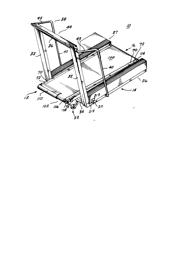
Referring initially to FIGURES 1 and 2, the present invention is illustrated
15 as embodied in the form of an exercise treadmill. The exercise treadmill 10
includes a deck assembly 12 having a rear end portion pivotally mounted on an
underlying frame 14. An endless belt assembly 16, mounted on the deck assembly,
is powered by an electric motor 18. The forward end of the deck assembly 12 is
supported by a suspension system 20 allowing the deck assembly to retract or yield
20 in the downward direction at a graduated rate under the impact forces of a runner
landing on the deck assembly, and then return upward to its nominal position as
the runner is taking his next stride. The typical shock loads imparted on a runner's
feet and legs by conventional exercise treadmills are largely avoided in the
present invention. As a result, the likelihood of injury occurring to the runner,
25 especially over a prolonged duration, is vastly decreased. The present invention
also utilizes a li~t mechanism 22 to raise and lower the forward end of the
frame 14, for instance, to simulate running up an incline.
To more fully describe the present invention, the frame 14 is constructed
with a pair of longitudinal side rails 26 and 27 each having lower, floor engaging
30 tubular section 26a and 27a, respectively, and upper box sections 26b and 27b,
respectively, disposed thereon. As shown in FIGIJRES 1, 2, 3a and 4, the upper
box sections 26b and 27b extend laterally outwardly of their corresponding lowertubular sections 26a and 27a. The side rails 26 and 27 are interconnected by
rearward and intermediate transverse cross members 28 and 30, respectively. For
35 high strength relative to their weights, ideally the side rails and the rear and
intermediate cross members of the frame 14 are all composed of tubular material
or formed as box members of rectangular cross-sectional shapes.
-6- ~32~
A pair of front tubular posts 32 extend upwardly from the forward ends of
the frame side rails 26 and 27 while sloping diagonally forwardly. The lower ends
of the posts 32 are bolted to formed brackets 33 each having a longitudinal
section 33a extending along the outer upper edges of the tubular sections 26a and
5 26b and a transverse section 33b extending across the front of the side rails 26 and
27 within the cross-sectional profile of the corresponding upper box sections 26b
and 27b. Attachment bolts, not shown, extend through clearance holes formed in
the bracket transverse section 33b and engage within the threaded openin~ in theposts 32. Below the brackets 33, a formed, inverted U-shaped front cross
10 member 34 transversely interconnects the posts 32.
The upper ends of the posts 32 are interconnected by the center section 36
of a handrail 38. Ideally the ends of the handrail center section 36 extend through
aligned clearance openings formed in the side walls of the front posts. The
handrail 38 also includes formed side sections 40 that extend laterally outwardly
15 from the front posts, curve substantially rearwardly and slightly downwardly and
then curve substantially downwardly and slightly rearwardly to the elevation of
the frame side rails 26 and 27. At the frame side rails, the handrail side
sections 40 curve transversely inwardly to intersect the lower tubular sections 26a
and 27a of the frame side rails. The lower ends of the side rail sections 40 may be
20 secured to the outside walls of the tubular sections 2fia and 27a by any appropriate
method. Ideally, but not essentially, the handrail 38 is composed of round tubular
material. Also, ideally at least the center section 36 and the upper portions of the
side sections 40 of the handrail 38 are sleeved with a resilient grip material 43,
such as closed cell foam, to assist the user in achieving a secure grip on the
25 handrail.
Referring specifically to FIGURES 1 and 2, a tilted display panel 44 spans
across the upper ends of the frame posts 32. As shown in FIGURE 2, the display
panel has a plurality of digital display areas 46a, 46b, 46c and 46d for displaying
various workout parameters, such as the speed of the runner, the distance
30 traveled, the duration of the run, the calories expended by the runner, the angle oî
inclination of the deck assembly 12, etc. A larger, center LED (light emitting
diode) display 47 is employed to depict various courses that can be chosen by the
runner or walker as well as the location of the runner/walker on the course.
Control buttons 48a through 481 are located on the panel 44 to control various
35 functions such as the speed of the endless belt assembly 16, the inclination of the
'~32~8~
--7--
functions such as the speed of the endless belt assembly 16, the inclination of the
deck assembly 12, the course selected for running and the parameters selected for
display, and also to bring the motor 18, and thus also belt assembly 16, to a rapid
stop.
Next referring specifically to FIGURE~ 1, 2 and 4 the deck assembly 12
includes a longitudinal, rectangular shaped ~leck member 70 bordered along its
sides by side re3nforcing members 72. As shown in FIGURE 1, the deck
assembly 12 extends forwardly beyond front end of the frame 14. The back of the
deck assembly 12 is pivotally mounted on the rear of the frame 14 through the use
lO of a rear cross bar 74 extending across the rear of the deck member 70 and across
the rear of the side members 72 to extend laterally beyond the side members. Thecross bar 74 is attached to the deck side members 72 by the transverse collar
portions 76 of end caps 78 which are secured to the rear ends of the side
members 72. Grooved caps 80 are engaged over the laterally outward ends of the
15 rear cross bar 74, which caps are each formed with a c;rcumferential groove 82,
sized for closely engaging within an outwardly open slot formed in the forward,
upper edge portion 83 of the vertical web 84 of an L-shaped mounting
bra~ket 86. The bottom flanges 88 of the brackets 86 overlap the upper surfaces
of auxiliary frame portions 89 located along the insides of the frame lower tubular
20 sections 26a and 27a. The width of the groove 82 is only slightly wider than the
thickness of the bracket web 84 to prevent any appreciable movement of the deck
assembly 22 laterally relative to the frame 14 while permitting the deck assembly
to freely pivot relative to the frame about a transverse axis 90 coinciding with the
central axis of the rear cross bar 74.
Next, referring primarily to FIGURES 1, 2 4 and 5, a belt assembly 16 is
associated with the deck assembly 12 for presenting a moving operative surface to
the runner or walker. The belt assembly 16 includes an endless belt 100 having its
upper, operative surface riding over the top of the deck assembly 12, its forward
and rearward ends trained around forward and rearward roller assemblies 102 and
30 104, respectively, and its bottom surface spaced slightly below the bottom of the
deck assembly 12. The forward roller assembly 102 includes a forward idler
roller 106 rotationally mounted on brackets 108 secured to the forward ends of the
deck side members 72. The brackets 108 and roller 106 are shielded by a formed
cover 110 spanning across the front of the deck assembly 12 to encase the forward
35 roller and the end caps. It will be appreciated that the cover 110 not only
'~32~3
--8--
protects the forward roller 106, but also by extending upwardly above the
operative surface of the endless belt 100 reduces the likelihood that the runner's
foot will land forwardly beyond the endless belt.
The rear roller assembly 104 includes a drive roller 114 mounted on a drive
5 axle 116 by right and left end caps 11~ and 12û which are pressed onto the interior
of the ends of the drive roller. The end caps 118 and 120 have circular eentral
bores 121R and 121L for receiving the drive axle 116. Ideally, the bore 121R
formed in the right end cap 118 is formed with a slight taper in the outward
direction to match a corresponding taper formed in the drive axle 116. Also,
lO ideally the central bore 121L of the left end cap 120 is of a constant diameter for
snugly receiving a bushing 122 therein. ~aterally outwardly of the end cap 120,
the left end portion of the drive axle 116 engages through the inner race of an
antifriction bearing 124, and correspondingly the portion of the drive axle 116
laterally outwardly from right end cap 118 engages through the inner race of an
15 antifriction bearing 126. The outer races of the bearings 124 and 126 are pressed
within generally disc-shaped bearing retainers 128. A groove 130 extends around
the outer circumference of the bearing retainers. The groove 130 is sized to fitclosely within an upwardly open slot formed in the rear upper edge portion 132 of
the webs 84 of the mounting brackets 86. It will be appreciated by the foregoing20 construction that the rearward roller assembly 104 is held in engagement with the
mounting brackets 86 without any further retention device.
As illustrated in FI~;URE 5, the antifriction bearing 124 is retained on the
left end portion of the drive axle 116 by a threaded hardware member 134 that
engages within a tapered, threaded blind hole formed in the end of the drive
25 axle. A diametrical cross slit 135 is formed in the end of the drive axle to allow
the drive axle to expand outwardly as the hardware member 132 is threadably
engaged with the axle. As a result, the end of the drive axle is securely engaged
within the inside diameter of the bearing 124 without having to grind or otherwise
precisely machine the end of the drive axle as would typically be required.
A drive pulley 136 is engaged over the right end of the drive axle 116. A
key 138 is engaged within a close-fitting keyway formed longitudinally in the right
end of the drive axle 116 and within a corresponding keyway formed in the wall of
a bore extending through the center of the pulley 136 to prevent relative
rotational movement between the pulley and the drive axle. It will be understood35 that other standard methods could be employed to prevent relative rotational
movement between these two components. For instance, the end of the drive axle
could be formed with male spines to match female spines formed in the inside
2 ~ 3 ~
g
diameter of the drive pulley 136. A threaded hardware member 140 is engaged
within a threaded blind hole formed in the right end of the drive axle 116, thereby
tightly clamping the center portion of the right end cap 118 to one side of the
inner race of the bearing 126, while tightly clamping the central hub 142 of the5 drive pulley 136 to the opposite side of the bearing inner race. It will be
appreciated that the tightening of the hardware member 140 will cause the
tapered section of the drive axle 116 to wedge tightly within the correspondingly
tapered central diameter of the right end Cap 118 to prevent any relative rotation
therebetween.
lO Th~ pulley 136 is driven by an electric motor 18 through the intermediacy of
a drive belt 146 in a standard manner in powered eXerCiSe eqUipment~ including
exercise treadmills, of the nature of the preSent invention. A flywheel 148 is
mounted on the output shaft of the motor 18 to help ensure that the endless
belt 100 will be driven at constsnt speed even when the runner's feet land on the
l 5 endless belt.
As most clearly shown in FIGURES 2, 3a and 6, the suspension system 20 for
the deck assembly 12 includes pivotable lever arms 160L and 160R mounted on the
upper surfaces of the lower tubular rail sections 26a and 27a at the forward ends
of the frame side rails 26 and 21 along each side of the deck assembly 12. Stub
20 shafts 162 extend transversely outwardly from the lever arms 160L and 160R toengage within close-fitting bushings 164 disposed within cylindrical hubs 166
mounted on the upper surface of frame lower tubular sections 26a and 27a by the
rear portion of the side sections 33a of the post brackets 33. The inward ends of
the hubs 166 are secured to the tubular sections 26a and 27a by upright
25 plates 167. A diagonal wedge plate 168 extends diagonally downwardly from therear side of the hubs 166 to the upper surface of the frarne lower tubular
sections 26a and 27a. The stub shafts 162 cooperatively define the pivot axis 169
of the lever arms 160L and 160R. A snap ring 170 or other appropriate hardware
member is employed to retain the stub shafts 162 engaged with the hubs 166.
Referring additionally to FIGURE 3b, the lower end of a rocker arm
assembly 174 and the forward, free rod end 176 of a linear actuator, in the formof a fluid cylinder or shock absorber 178, are pivotally and antifrictionally
mounted on the rearwardly extending end of the lever arms 160L and 160R to
pivot about a common axis 180. To this end, a circular eye 182, formed at the
35 forward, free end 176 of the shock absorber 178, engages a close-fitting stubshaft 183 extending transversely from the inside face of the lever arms 160L and160R. Ideally, a bushing 184 or other anti~riction device is interposed between the
-10~
eye 182 and the stub shaft 183 to minimize friction resistance therebetween.
Also, a spherical socket 185, composing the lower end of the rocker arm
assembly 174, is also engaged over the stub shaft 183. A threaded bolt 186 is
engaged with a threaded central, blind bore formed in the stub shaft 183 to retain
5 the eye 182 and spherical socket 185 on the stub shaft. A washer 187 is positioned
between the eye 182 and the adjacent spherical socket 185 to allow these
components to freely pivot relative to each other.
The upper end of each of the rocker arm ass~mblies 174 is composed of a
ball stud 188 for engaging within close-fitting socket 190 pressed within a blind
lO bore formed in the underside of the deck side members 72. It will be appreciated
that the length of the rocker arm assemblies 174 may be adjusted by varying the
engagement of the lower spherical socket 185 and upper ball stud 188 within the
threaded ends of the rod or shank portion 192 of the rocker arm assemblies. The
lengths of the rocker arm assemblies 174 can be ~hanged to alter the nominal
15 height or elevation of the forward end of the treadmill deck assembly 12.
The rear ends of the shock absorbers 178, as shown in FIGURE 2, are
mounted on studs 196 extending transversely outwardly from the inner side walls
of the lower tubular sections 26a and 27a of the frame side rails 26 and 27.
Eyes 197 are formed in the rearward attachment portions of the shock absorbers
20 to engage over the studs 196. Ideally, the shock absorbers 178 act as "one-way"
shock absorbers or dampers to resist extension of the shock absorbers cylinders
but permit substantially free compression of the shock absorbers. Shock absorbers
of the nature of dampeners/shock absorbers 178 are standard items of
com merce.
The lever arms 160R and 160L are biased to return the deck assembly 12
upwardly to its nominal position by extension springs 200 acting between the
forward ends of the lever arms and the forward ends of pivot arms 202 extending
nominally forwardly from a cross rod 204 spanning between the forward ends of
the frame side rails 26 and 27. As shown in FIGURES 3a and 6, a hook 206 at one
30 end of the extension spring 200 engages through a cross hole formed in the
forward end of the lever arms 160R and 160L. A second hook 208 at the opposite
end of each extension spring 200 extends through a cross hole ~ormed in the
forward end of the pivot arm 202, which pivot arm projects transversely and
generally forwardly from the cross rod 204. The cross rod pivots within aligned
35 cross holes 210 formed in the frame side rails 26 and 27. The left hand end 211 of
the cross rod 204, as shown in FIGURES 1 and 3a, is formed in a U- or hook-
shape to define a terminal end portion 212 which is engagable within one of a
3~0~
series o-e cross holes 213 formed in the exterior side wall of the frame side
rail 2~. It will be appreciated that the cross rod 204 is capable of sliding along its
length within the cross holes 210 to permit the terminal end 212 of the cross rod
to be disengaged from one of the holes 213, the cross rod pivoted, and then the
5 terminal end of the cross rod reinserted into another hole 213. The particularhole 213 within which the terminal end 212 of the cross rod 204 is inserted af4ects
the nominal angular orientation of pivot arms 202 about the cross rod which in
turn varies the level of the biasing load being applied to the pivoting lever
arms 160R and 160L. It will be appreciated that the hook 211 could alternativelylO or in addition be Yormed in the opposite end of the rod 204.
Referring specifically to FIGURE 2, the lower end of a compression
spring 214 is mounted on a retainer ledge 215 projecting transversely inwardly
from the inside wall of frame side rail 27 at a location intermediate the ends of
the frame side rail. The upper end of the compression spring 214 bears against the
15 underside Oe the corresponding deck assembly side member 72. The compression
spring 214 functions to assist in upwardly supporting the deck assembly 12.
To describe the operation of the suspension system 20, a runner's forward
foot initially lands on the forward end of the deck assembly 12, is carried
rearwardly along the deck assembly by the moving endless belt lO0 past the
20 opposite foot and then is lifted off the deck assembly by the runner a short time
prior to the landing of the runner's opposite foot on the forward end of the deck
assembly. As the runner's foot lands on the deck assembly, the downward force
imposed thereby on the deck assembly causes the deck assembly to pivot
downwardly about the rear axis 90. The suspension system of the present
25 invention imparts a progres9ively increasing reaction force on the descending deck
assembly and absorbs much of the energy applied to the descending deck assembly
by the runner, thereby reducing the shock loads that would otherwise be
transmlttad to the runner's body by landing on an unyielding sureaae.
In basIc operation Oe the suspension system, the downward movement of the
30 de¢k assembly 12 and thus also the rocker arm assemblies 17g causes the leverarms 160R and 160L to pivot clockwise about the uxis 169, (FIGURE 6). This
results in an extension Oe the eluid shock absorbers 178 and also extension of the
springs 200 and compression of the spring 214. As described more fully below, inessence, the descent of the deck assembly 12 results in an increase in the
35 mechanical advantage or "leverage" Oe shock absorbers 178 acting on the leverarms 160R and 160L and a decrease in the mechanical advantage ~r "leverage" of
the rocker arm assemblies 174 acting on the lever arms, and also an increase in
. ' , - , .
-12- 2~ 0~i
the speed at which the shock absorbers are extended. These conditions increase
the resistance or "stiffness" of the suspension system 20 and cause the damping
force applied to the lever arms 160R and 160L to progressively increase during the
descent of the deck assembly.
To further elaborate, when the deck assembly 12 is in its nominal, fully
upward position, the line of action 216 of the shock absorbers 178 (extending along
the length of the shock absorbers) is at an effective distance 217 from the pivot
axis 169 of the lever alms 160R and 160L (shown in solid line in FIGURE 6) As
the deck assembly descends, the lever arms 160R and 160L pivot in the clockwise
10 direction toward the position shown in dotted line in FIGURE 6, causing the
junction axis 180 to swing about the pivot axis 169 of the lever arms to
progressively increase the effective distance separating the line of action 216 of
the shock absorbers 178 and the pivot axis 169. By the time the lever arms are in
the broken line position shown in FIGURE 6, the line of action 216 of the shock
l5 absorbers has incrementally increased to an effective distance 218 from the pivot
axis 169. This increase in the eff~ctive distance is essentially an increase in the
mechanical advantage or leverage of the shock absorbers on the lever arms.
Concurrently with the increase in the effective distance (from 217 to 218) of
the line of action 216 of the shock absorbers from the pivot axis 169, the line of
20 action 219 of the rocker arm assemblies 174 (coextensive with the length of the
rod 192) shifts significantly closer to the pivot axis 169 of the lever arms 160R
and 160L as the lever arms rotate from the solid line position shown in FIGURE 6to the broken line position. For example, as shown in FIGURE 6, with the deck
assembly 12 in its nominal position, the line of action 219 of the rocker arm
25 assemblies 174 is at an effective distance 220 from the pivot axis 169 of the lever
arms 160R and 160L. As the lever arms 160R and 160L pivot in a clockwise
direction toward the position shown in dotted line in FIGURE 6 due to the
displacement or lowering of the deck assembly, the line of action 219 of the
rocker arm assemblies moves toward the pivot axis 169 a significantly decreased
30 effective distance 222. As a result, the mechanical advantage or leverage of the
rocker arm assemblies 174 on the lever arms is significantly decreased.
As the deck assembly 12 descends, the increase in the leverage of the shock
absorbers 178 is related to the decrease in the leverage of the rocker arm
assemblies 174 essentially as a function of the tangent of the angle oL that the35 lever arms 160R and 160L are from a horizontal reference line, as shown in
FIGURE 6. Thus, since the tangent of the angle ~ increases significantly as the
lever arm pivots from the solid line position to the broken line position shown in
2 ~ ~ 2 ~
-13-
FIGURE 6, especially when the angle is greater than Ir/2~ the damping resistance
provided by the shock absorbers increases significantly with the clockwise rotation
of the lever arms 160R and 160L, and thus also with the downward movement or
depression of the deck assembly 12.
5 The novel suspension system 20 of the present invention in addition to
increasing th~ mechanical advantage of the shock absorbers 118 on the lever
arms 160R and 160L during descent of the deck assembly 12, concurrently causes
the shock absorbers 178 to be extended at an increasing rate. The fluid shock
absorb~rs 178 are of a t'one-way" design to resist extension, thereby absorbing
10 energy during their extension while imposing very little resistance to their
retraction or shortening. As in typical dampening devices, the capacity of the
shock absorbers 78 to absorb energy is a function of the square of the velocity at
which the shock absorbers are extended in length.
It will be appreciated that as the lever arms 160R and 160L begin to pivot in
15 a clockwise direction, shown in FIGURE 6, about the pivot axis 169 from the
position shown in solid line toward the position shown in dotted line, due to the
initial orientation of the lever arms ~generally aligned with the shock absorbers),
at first the fluid shock absorbers 178 extend very little relative to the amount of
elevational descent of the deck assembly 12. Since the resistance imposed by the20 shock absorbers 178 to the rotation of the lever arms 160R and 160L is a function
of the rate at which the shock absorbers are extended, the shock absorbers
initially do not exert significant resistance to the rotation of the lever arms.However, as the lever arms rotate further about the pivot axis 169 toward the
position shown in dotted lines in FIGURE 6, the pivot joint 180 between the lever
25 arms 160R and 160L with the shock absorbers 178 moves at a faster rate away
from a line extending between the axis 169 and shock absorber mounting stud
196. This results in the shock absorbers being extended at a substantially faster
rate relative to the rate of downward descent of the deck assembly 12. As such,
the shock absorbers 178 exert a progressively increasing level of damping on the30 deck assembly relative to the amount of damping exerted by the shock absorbers
during the initial descent of the deck assembly.
The damping force that the shock absorbers apply to the lever is a function
of the square of the rate of descent of the deck assembly 12 and the cube of thetangent of the angle ~. This is a reflection of the geometry of the suspension
35 system 20 as well as the fact that the damping resistance provided by the shock
absorbers is a function of the square of the velocity at which the shock absorbers
are extended. It will be appreciated that unless the descending velocity of the
-14- ~3,s~
deck assembly 12 is near zero~ ~he damping resistance exerted by the shock
absorbers 178 predominates in producing a reaction force in opposition to the
rotation of the leYer arms 160A and 16ûL. Although certain amount of resistance
to the rotation of lever arms is produced by the extension of the springs 200 and
5 the compression of the auxiliary spring 214, preferably the total resistance
provided by these springs is only a fraction of the resistance generated by the
shock absorbers 178.
As a result of the foregoing, the resistance to the downward movement of
the deck assembly 12, and thus also the runner's foot, progressively increases as
I 0 the deck assembly is displaced in a downward direction. Eventually the downward
force being applied to the deck assembiy by the runner is matched by the resisting
force imparted on the deck assembly by the shock absorbers 178 and the
springs 200 and 214, so that by the time the runner's foot reaches a point where it
has to shove off the deck assembly 12, the suspension system 20 is substantiallyI 5 rigid. The deceleration of the runner's foot during footfall occurs much more
gradually than if a substantially constant resistance force were applied to the
deck assembly, for instance through the use of compression springs similar to
auxiliary springs 214. Aecordingly, the shock (which can be considered to be therate of change of acceleration) imposed on the runner's feet, ankles and legs is20 substantially decreased through the present invention, providing a reduction in the
likelihood of injuries sustained by the runner, especially over prolonged periods of
time.
When both of the runner's feet are momentarily lifted off the deck
assembly 12, the springs 200, acting on the forward end of the lever arms 160R
25 and 160L, cause the lever arms to pivot counterclockwise (as shown in FIGURE 6)
about the axis 169, thereby to push the forward end of the deck assembly back
upwardly to its nominal position. In this regard, the springs 200 are assisted by
the auxiliary spring 214. As mentioned above, the counterclockwise rotation of
the lever arms 160R and 160L is not resisted by the shock absorbers. As such, the
30 deck assembly is capable of being returned to its nominal position in a very short
time span, typically a fraction of a second.
To accommodate runners of various weights, the initial biasing force
imposed on the lever arms 160R and 160L by the springs 2U0 may be adjusted by
changing the position of the pivot arms 202 assoeiated with the cross rod 204 by35 selective engagement of the cross rod terminal end 212 within the reception
holes 213. Rotation of the pivot arms 202 in the eounterclockwise direction shown
in FIGURE 6 results in a corresponding counterclockwise nominal rotation of the
-15- 2~32~ ~
lever arms 160R and 160L, thereby decreasing the initial angle u and the initialeffective distance 217 separating the line of action 216 of the shock ~bsorber~ 178
from the lever arm pivot axis 16~. As a result, the suspension system 20 is
adjusted to a "less stiff~ mode permitting increased downward displacement of the
5 forward end of the deck assembly 12 than if the pivot arms 202 were positioned to
nominally orient the lever arms 160R and 160L in a more clockwise orientation. If
the lever arms 160R and 160L are initially positioned in a more clockwise
orientation, the initial angle ~ and the initial effective distance 217 separating the
line of action 216 of the shock absorbers 178 from the pivot axis 169 would be
l 0 increased, thereby increasing the initial mechanical advantage of the shock
absorbers. As a result, the lever arms pivot through a shorter arc for a given load
imposed on the deck assembly, resulting in a more stiff configuration of the
suspension system 20.
From the foregoing construction it will be appreciated that various
15 alterations can be made in the suspension system 20 without departing from the
spirit or scope of the present invention. For instsnce, rather than being mounted
on the frame side rails 26 and 27, the lever arms 160R and 160L can be instead
mounted in "reverse pos3tion" on the deck assembly 12. In this configuration, the
shock absorbers 178 and the cross rod 204 would also be mounted on the deck
20 assembly, and the free end of the rocker arm assemblies 174 would push
downwardly against the frame 14 rather than upwardly against the deck
assembly. One dissdvantage of reversing the position of the suspension system inthis manner is that the sprung weight of the deck assembly would be increased,
thereby increasing the level of energy which would have to be absorbed by the
25 shock absorbers 178 and resisted by the springs 200 and 214.
It will also be appreciated that, in theory, the shock absorbers 17~ could be
eliminated, with the function of the shock absorbers being accomplished by
significantly increasing the stiffness of the springs 200 and/or 214. Unfortunately,
this would result in a decrease in the downward travel distance of the deck
30 assembly, and thus likely would inorease the shock experienced by the runner's
feet.
As a further alternative, it is possible that the shock absorbers 178 and
springs 200 and/or spring 214 may be replaced by a combination shock absorber
spring unit, which are commonly commercially available. As a further possible
35 alternative, the shock absorbers 178 and springs 200 and/or spring 214 may be
-16- ~32~a
replaced by a gas filled shock absorber which exhibits both the damping
characteristies of a standard shock absorber and the load carrying characteristics
of a spring.
Next re~erring specifically to FiGURES 2 and 3a, the li~t mechanism 22 of
5 the present invention includes a pair of tubular, arcuate arms 230 disposed
longitudinally alongside the inward sides of the frame side rails 26 and 27. Thearms are curved in a concave downward direction and are interconnected
intermediate their ends by a transverse cross bar 232. A pair of rollers or
wheels 234 are engaged on an axle 236 interconnecting the forward ends of the
10 arcuate arms 230.
The arcuate arms 230 are constrained to move only in the fore and aft
directions by forward and rearward guides 238 and 240. The forward guides 238
are generally wedge-shaped, having an arcuate lower surface corresponding to thecurvature of the arms 230. The forward guides 238 are engagable within a
15 downwardly open slot 241 formed in the rear wall 242 of the forward cross
member 34 of the frame 14. Preferably, the forward guide 238 is formed from a
reduced friction material, such as a plastic or nylon.
The rear guides 240 are held in place on the top of the intermediate cross
member 30 by U-shaped retainers 243. The upper surfaces of the rear guides 240
20 are curved to match the curvature of the underside of the arcuate arms 230. As
with the forward guides 238, preferably the rearward guides 240 are composed of
a reduced friction material, such as plastic or nylon. It will be appreciated that at
their forward ends, the arms 230 bear upwardly against the forward guides 238,
while at their rearward ends, the arms bear downwardly against the rearward
25 guides 240.
As illustrated in FIGURE 3a, the two arcuate arms 230 are in unison pushed
forwardly or pulled rearwardly by an actuating tube 44 which is pivotally pinned to
spaced apart ears 246 projecting transversely rearwardly from cross bar 232 by across pin 248 extending through aligned cross holes formed in the ears and also
30 through aligned clearance holes formed in the actuating tube. Referring
additionally to FIGURE 2, at its rearward end, the actuating tube 244 is
threadably engaged with a screw shaft 250. The screw shaft 250 is rotated
relative to the tube 244 by an electric motor 252 through the use of a speed
reduction unit 254~ The operation of the electric motor 250 is controlled by
35 control buttons 48 mounted on the display panel 44, discussed above.
It will be appreciated that by the foregoing construction, the lift
mechanism 22 is disposed entirely beneath the deck assembly 12 and between the
-17- 2~32a~3
sides of the frame 14, thereby maintaining the pleasing appearance of the present
invention. In typieal treadmill lift mechanisms, components of the mechanism
protrude upwardly above the elevation of the deck assembly.
An alternative preferred embodiment of the present invention is illustrated
5 in FIGURES 7a, 7b and 7c, wherein a socket 190' for receiving the upper end 188'
of a rocker arm assembly 174', is integrated within a longitudinal slide 270
disposed within a slideway 272 formed in the side members 72' of the deck
assembly 12'. The components of the present invention, illustrated in
FIGURES 7a, 7b and 7c, corresponding to similar components shown in
10 FIGURES 1-6 are indicated with the same part number, but with the addition of a
prime (') designation. The slide 270 may be longitudinally shifted by operation of a
knob 274 extending upwardly from the slide within a clearance slot 276 formed inthe deck side members 272 above the slide 270. Preferably, the top of the
knob 274 does not protrude above the top surface of the deck side members 72',
l5 thereby to prevent the knob from being accidentally shifted by the runner's foot.
A cover, not shown, can be provided to close off the top of the slot 276. A
plurality of detents, for example, 278a, 278b and 278CI can be formed within thedeck side members 72' for reception of a spring-loaded detent ball 280 mounted
within the slide 270. As will be appreciated, the engagement of the detent
20 ball 280 within the detents 278a, 278b and 278c enables the slide to be shifted to
specific locations along the slideway and held in place until being shifted again.
As illustrated in FIGURE~ 7a, 7b and 7c, the position of the socket 190'
along the deck side member 72' has an effect on the effective distances between
the lines of action of the rocker arm assembly 174' and the pivot axis 169' of the
25 lever arms 160L' and 160R. The lever arms are depicted in solid line in theirmaximum counterclockwise position (deck assembly 12' in nominal, fully up
location) and depicted in dotted line in clockwise'position (deck assembly 12~ in
fully downwardly displaced location) about axis 169'. The lines of action for the
various positions of the socket 190' are illustrated in FIGURES 7a, 7b and 7c.
As illustrated in FIGURES 7a and 7b, when the socket 190' is positioned so
that the detent ball 280 is within detent 278a, the initial effective distance 300a
between the line of action 302a of the rocker arm assembly 174' and the pivot
axis 16g' is less than the initial effective distance 300b between the line of
action 302b of the rocker arm assembly and the pivot axis 169' when the detent
35 ball 280 is within detent 278b. This also holds true for the effective distance 304a
between the line of action 302a of the roller arm assembly 174' and the pivot
axis 169 when the rocker arm assembly is in the rotated position shown in dotted
-18- 2 ~ 3 ~
line in FIGUREiS 7a and 7b. Thus, positioning the socket 190' so that the detentball 280 is engaged within detent 278a constrains the lever arms 160L' and 160R'to rotate through a smaller arc for a given load imparted on the deck assembly 12'
by the runner's foot. As such, the suspension system 20' is adjusted to a stiffer
5 position than if the detent ball were disposed within detent 278b.
Conversely, when the socket 190' is shifted in the opposite direction so that
the detent ball 280 is disposed within detent 278c, the effective distances 300cand 304c separating the line of action 302c of the rocker arm assembly 174' fromthe pivot axis 169' is increased. This permits the lever arms 160L' and 160R' tol0 pivot about a larger arc for a given load imposed on the deck assembly 12'. AS a
result, the suspension system 20' is adjusted to a "softer" condition.
It will be appreciated that by adapting the socket 190' to shift longitudinally
along the deck side members 72', the function of the pivot arms 202 of the
embodiment of the present invention shown in FIGURES 1-6 may be replaced
l 5 and/or augmented. Thus, in the embodiment of the present invention shown in
FIGURES 7a, 7b and 7c, it is possible to adjust the suspension system 20' along a
larger range than is possible by utilizing the pivot arms 202 themselves.
Other than as described above, the construction and operation of the
embodiment of the present invention shown in FI&URES 7a, 7b and 7c is the same
20 as the embodiment shown in FIGURES 1-6. As suchJ the same advances in the artand advantages provided by the preferred embodiment of the present invention
shown in FIGURES 1-6 are also provided by the preferred embodiment of the
present invention shown in FIGURES 7a, 7b and 7c.
It is to be understood that while preferred embodiments of the present
25 invention have been illustrated and described, various changes can be made
therein without departing from the spirit or scope of the present invention. Forinstance, the present invention may be adapted to exercise devices other than
exercise treadmills. Accordingly, the present invention is defined by the following
claims rather than being limited to the specific embodiments of the present
30 invention described above.