Note: Descriptions are shown in the official language in which they were submitted.
2 ~ 8 ~
OPrIMIZED WAVELlENGTH-DIVISION-MULTIPLEXED
LIGHTVVAYE COMMUNICATION SY5TEM
Technical Field
This invention relates to wavelength-division-rnultiplexed lightwave
S communication systems and, more particularly, to such systems in which one or
more carrier signals are transmitted at a wavelength of ~ero dispersion for the
dielectric waveguide transrnission medium of the system.
Background of the Invention
Optical fibers are generally accepted as the transmission medium for
10 most long distance lightwave communication systems. Theoretically, because ofalmost unlirnited bandwidth, fibers can transport thousands of very high speed data
channels simultaneously. Realistically, however, loss, dispersion, and nonlinearintensity-dependent effects combine to determine both the number of channels
supported by the fiber and the spectral placement of the channels on the fiber. In an
15 effort to reach a maximurn data throughput rate, most communication systems are
designed as wavelength-division multiplexed (WDM) or frequency-division-
multiplexed (PDl!iI) systems ha~/ing carrier signals transmitted at and in closeproximity to a benchmark transmission characteristic for the optical fiber, namely,
the zero dispersion wavelength, ~0. This wavelength is defined as the point at which
20 the second derivative of the propagation constant for the fiber taken with respect to
wavelength is zero. Standard single-mode fibers exhibit zero dispersion norMnally at
1.3~,1m, while dispersion-shifted fibers have a zero dispersion point at approximately
l.S~lm.
While it has remained a foregone conclusion that one carrier in a WDM
25 or FDM system be transmitted at the zero dispersion wavelength, the placement of
other carriers ~or adjacent channels has been a subject of important study. In fact,
several researchers have modeled the problem of carrier placement as a three-wave
or four-wave mixing problem to account for nonlinear effects arising when intense
lightwave signals propagate in the optical fiber. See, K. O. Hill et al., J. Appl. Phys.,
30 49(10), pp. 5098-5106 (1978) and N. Shibata et al., EEE J. Quant. Elect., Vol. QE-
23, No.7, pp.l205-1210 (1987). Both Hill et al. and Shibata et al. describe
processes in which three input lightwave signals with different frequencies generate
lightwave signals at as many as nine corresponding new frequencies. The new
`
2~32~
, ,
lightwave signals result ~rom fre~uency mixing or crosstalk. Shibata et al. conclude by
extrapolating their results from experiments at short wavelengths that, in a frequency
multiplexed transmission system with one narrow linewidth carrier signal at the zero
chromatic dispersion wavelength of the fiber, transmission of adjacent lightwave signals
S should occur with frequency separations greater than 400 GHz (2.25nm) at ~0 = 1.311m
and greater than 300 G~Iz (2.~nm) at ~0 = 1.5~m to achieve complete suppression of
lightwave signals generated through four-wave mixing. It is now understood by me that
the conclusion by Shibata et al. is flawed and that complete suppression does not occur
in the frequency multiplexed system described by Shibata et al.
10 Summary of the Invention
In accordance with one aspect of the invention there is provided transmitter
apparatus for generating lightwave signals to be wavelength-division-multiplexed in an
optical fiber having a mean zero dispersion wavelength associated therewith, said
transmitter apparatus comprising at least first and second channel transmitters, each
15 transmitter including a light source and a modulating means optically coupled together,
each said light source for generating a lightwave signal substantially at a carrier
wavelength, said carrier wavelength for said first channel transmitter being at least 0.4nm
below said zero dispersion wavelength, a difference between said carrier wavelengths for
said at least first and second channel transmitters being greater than or equal to 2nm.
In accordance with another aspect of the invention there is provided a
lightwave system comprising transmitter apparatus and optical fiber coupled thereto for
transmitting lightwave signals in an N-channel wavelength-division-multiplexed format in
said fiber, N being a positive integer greater than or equal to 2, said optical fiber having
mean zero dispersion at a predetermined wavelength, said transmitter apparatus
25 comprising at least first and second channel transmitters, each transmitter including a light
source and a modulating means optically coupled together, each said light source for
generating a lightwave signal substantially at a carrier wavelength, said carrier wavelength
for said first channel transmitter being at least 0.4nm below said zero dispersion
wavelength, a diE~erence between said carrier wavelengths for said at least first and second
30 channel transmitters being greater than or equal to 2nm.
:
- -2a- 2~32~9
Unwanted, monotonic growth of sideband energy is avoided in wavelength-
division-multiplexed and frequency-division-multiplexed lightwave communication systems
by transmitting adjacent channels approximately 2nm or more apart in the normal
dispersion regime of the optical fiber and by transmitting each channel more than 0.4nm
5 below a mean zero dispersion wavelength, ~.0, of the optical fiber. Interchannel spacing
and individual channel separation from the zero dispersion wavelerlgth are measured with
respect to a nominal carrier wavelength for each channel.
Each transmitter in the wavelength-division-multiplexed or frequency-division-
multiplexed lightwave communication system includes a plurality of modulated light
10 sources allocated on the basis of one per channel, wherein each light source is tuned to
a particular wavelength in accordance with the desired interchannel spacing and individual
separation from the zero dispersion wavelength. Light sources include tunable and fixed
wavelength lasers modulated directly or externally.
Brief Description of the Drawin~
A more complete understanding of the invention may be obtained by reading
the following description of a specific illustrative embodiment of the invention in
conjunction with the appended drawing in which:
FIG. 1 is a simplified block diagram for the lightwave communication system
in accordance with the principles of the invention;
:`~
2032089
FIG. 2 shows a plot of fiber dispersion versus wavelength for a standard
single-mode fiber,
FIG. 3 shows the relationship between channel carriers and
intermodulation sidebands for a 2-channel wavelength division multiplexed
5 lightwave communication system;
FM. 4 shows a graph of cumulative random dispersion as a function of
position on the fiber;
FIG. S shows a plot of SpUIiOUS sideband signals produced by four
photon mixing of two primary sin~soidal waves;
FIG. 6 shows a sequence of exemplary input data pulses for a channel in
the WDM lightwave communication system;
F~Gs. 7 through 10 show output pulses for a 2-channel WDM lightwave
communication system for both channels and the sideband intermodulation channelswhen one carrier wavelength is positioned at the zero dispersion wavelength of the
15 optical fiber;
FIGs. 11 and 12 show input and output spectra, respectively, for the
signals described in FIGs. 6 through 10;
FIGs. 13 tl~ough 18 show output signals for a 2-channel WDM
lightwave communication system for both channels and the sideband
20 intermodulation channels when one carrier wavelength is positioned aw~y from the
zero dispersion wavelength of the optical fiber in accordance with the principles of
the invention; and
FIGs. 19 and 20 show input and output spectra, respectively, for the
signals descIibed in FIG. 6 and FIGs. 16 through 18.
25 Detailed Description
Lightwave signal transmission over very long distances is encumbered
by the usual problems caused by loss and dispersion in th optical fiber. In addition,
such transmission is effected by a weak dependence of the fiber material refractive
index on the intensity of each lightwave signal. This dependence is nonlinear and
30 can be expressed as n = nO + n2- IEI2, where nO represents the linear part of the
refractive index, n2 represents the nonlinear part of the refractive index, and E is the
power dçnsity of the lightwave signal.
Dependence of refractive index on the intensity of the lightwave signal
induces a change of the group velocity for that lightwave. The refractive index
35 change also leads to self phase modulation or self chirping of the lightwave signal
2~32~9
which influences pulse shape via interaction of pulses from the lightwave signal with
the fiber dispersion Self phase modulation and dispersion cancel completely during
soliton formation. When cancellation is incomplete, self phase modulation leads to
spectral broadening and, as a result, additional pulse distortion.
In accordance with the principles of the present invention, the signal
distorting influence of the weak refractive index nonlinearity in optical fibers is
minimized for lightwave signals traveling distances comparable to present
transoceanic spans. This is achieved in a multi-channel wavelength division
multiplexed (WDM) lightwave cornmunication system by transmitting adjacent
10 channels approximately 2nm or more apart in the norrnal dispersion regime of the
optical fiber and also by transrnitting each channel more ~han 0.4nm below the zero
dispersion wavelength, ~0, of the optical fiber. While the interchannel separation
may be large, it has been determined from simulation results that an interchannel
separation between 2nm and 3nm is desirable for a WDM lightwave sys~em having
15 at least two channels bearing ASK modulated inforrnation. A large interchannel
separation is perrnitted by employing fixed or adaptive equalization elements at the
receive end of the communication system. Equalization elements known in the art
have both electronic and fiber realizations.
With respect to the separation of the first channel from the zero
20 dispersion wavelength, it has been found from simulation that the closer one channel
wavelength is to the zero dispersion wavelength, the more distortion is introduced
into the other channel for a 2-channel YVDM lightwave system. When viewed as
frequency spectra, it is seen that intermodulation increases and causes significant
arnounts of noise to occur across the wavelength band of interest. As the first
25 channel is farther from the zero dispersion wavelength, it is understood that both
channels of a 2-channel sys~em undergo considerably more dispersion.
It should be noted that the following conventions will be followed in
this descripdon for purposes of clarity and not for puIposes of limitation.
Wavelength division multiplexing is understood to encompass standard WDM and
30 frequency division multiplexing (FDM). Generally, WDM is understood to be thesame as FDM. Optical fiber is understood to include such types of optical fiber as
standard circular core, single mode fiber, dispersion shifted fiber, polarization
maintaining or polarization preserving fiber, and the like. Other conventions are set
forth in the description below.
2~32089
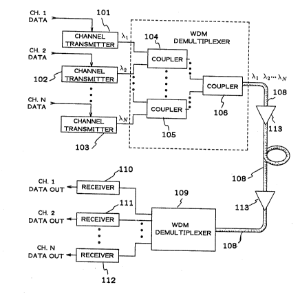
An exemplary multi-channel WDM lightwave communication system is
shown in FIG. 1. Each channel supplies data to a related channel transmitter. Data
from channel 1 are supplied to channel transmitter 101; data from channel 2 are
supplied to channel transrnitter 102; and data from channel N are supplied to channel
S transmitter 103. Channel transmitters 101 to 103 include sufficient elements well
known to those skilled in the art for generating lightwave signals modulated by the
respective channel data. In an exemplary embodiment, the channçl transmitter
includes a single wavelength laser diode such as a distributed feedback laser coupled
optically through an optical isolator to an external modulator. The laser diode is
10 suitably biased and controlled to operate in a continuous-wave (CW) mode at the
single wa~elength which is known herein as a carrier wavelength for the channel of
interest. CW lightwave signals from the laser diode are modulated by the channeldata in the external modulator to generate the modulated lightwave signal. The
modulated lightwave signals associated with a particular channel have a generally
15 wlder bandwidth than the unmodulated laser diode signal but, for purposes of ease in
description, such signals are considered to be nominally at the associated carrier
wavelength.
The transrnitter apparatus shown in FIG. 1 also includes a WDM
multiplexer 107 to combine the separate modulated lightwave signals into a single
signal for translrussion on optical fiber 108. As such, multiplexer 107 is an N x 1
device which accepts N different inputs and converts them to a single output. All
input wavelengths are present in the output signal from multiplexer 107. WDM
multiplexer 107 includes couplers such as 3dB couplers to combine pairs of
lightwave signals at different wavelengths into a single output lightwave signal.
The multi-wavelength signal output from WDM multiplexer 107 is
input to optical fiber 108. While the fiber is depicted simplistically as a single length
in FIG. 1, it will be appreciated by those individuals skilled in the art that optical
fiber 108 may comprise a plurality of long spans (lOkm or longer) of fiber separated
from one another by individual amplifiers, repeaters or regenerators to achieve long
30 distance communication. In this context, long distance is understood to mean
distances greater ~han lOOkm, for example. It should be understood by those persons
skilled in the art that this invention is particularly applicable to long distance WDM
systems spanning desirably more than lOOOkm because it is generally accepted that
the fiber nonlinearity only becomes significant over such very long distances.
35 Transmission over very long distances is improved by spacing optical amplifiers
along the length of the fiber to compensate intrinsic ISber loss. Several amplifiers
2032~8~
- 6 -
have been shown in FIG. 1 along the length of fiber lOB. Standard optical amplifiers
such as semiconductor amplifiers and doped-fiber amplifiers may be ernployed foramplification and loss compensation along the length of fiber 108.
In the WDM lightwave comrnunication system, multiplexed signals
S output from fiber 108 are supplied to WDM demultiplexer 109. VVDM
demultiplexer 109, as shown in FIG. 1, separates the different channels according to
wavelength so that the signal on carrier wavelength ~1 is sent to receiver 110, the
signal on carrier wavelength ~2 is sent to receiver 111, and so on through the signal
on carrier wavelength ~N which is sent to receiver 112. Receivers 110 through 112
10 de~ect and process the received lightwave signal information to produce a data
output signal for each particular channel of interest.
FIG. 2 shows the variation of dispersion with respect to wavelength for
a standard optical fiber such as fiber 108. Two distinct regimes are noted on
curve 20, namely, the anomalous dispersion regime (D>0) and the normal dispersion
15 regime (D~0). Curve 20 is shown crossing through a point of zero dispersion at
wavelength ~0. This wavelength is the so-called zero dispersion wavelength. Of
course, in dispersion-shifted fibers, this crossing occurs at a longer wavelength
(~l.SIlm). As described above, prior art WDM lightwave comrnunication systems
have been designed to ~ke advantage of the zero dispersion wavelength by
20 launching one channel of the WDM signal into the fiber at a carrier wavelength ~0.
In contrast and in accordance with the principles of the present invention, no channel
carrier is launched at the zero dispersion wavelength. Rather, carrier wavelengths of
adjacent channels are separated by approximately 2nm or more and the carrier
wavelength of each channel is separated a~ least 0.4nm away from the zero
25 dispersion wavelength.
Interchannel spacings and separation from the zero dispersion
wavelength is depicted for a 2-channel WDM lightwave communication system in
PIG. 3. As shown, channels 1 and 2 are transmitted at carrier wavelengths ~1 and~2, respectively. Channel 1 is shown as signal line 31 and channel 2 is shown as30 signal line 32. The spacing between these channels and the separation from the zero
dispersion wavelength, ~0, are in accordance with the teachings of the present
invention. Four photon mixing causes intermodulation or mixing signals to occur at
wavelengths ~3 and ~. The intermodulation sideband signals are refelTed to as
intermodulation channel 3 shown as signal line 33 and intermodulation channel 4 is
35 shown as signal line 34. Arrow 35 shows the direction of increasing wavelength.
-
2~32~8~
Alternatively, the relationships shown in FIG~ 3 can be viewed in termsof frequency according to the equation fi = c/~, for i=l, 2, 3, and 4. Channels 1 and
2 are transmitted at carrier frequencies fl and f2, respectively. Channel 1 is shown
as signal line 31 and channel 2 is shown as signal line 32. The spacing between
S these channels and the separation from the zero dispersion frequency, fO, are in
accordance with the teachings of the present invention. Four photon mixing causes
interrnodulation or mixing signals to occur at frequencies f3 and f4. The
intermodulation sideband signals are referred to as intermodulation channel 3 shown
as signal line 33 and interrnodulation channel 4 is shown as signal line 34. Arrow 36
10 shows the direction of increasing frequency.
Four photon mixing causes the intermodulation channels to occur at
well-defined wavelengths or frequencies. For the 2-channel WDM system described
above, the relationships between the channels may bè expressed as follows:
f3 = 2fl - f2 .
15 and
f4 = 2f2 - fl -
Of course, these relationships are easily converted to wavelength relationships by
employing the standard relationship ~at ~i - c/fi. where i=l, 2, 3, or 4 and fi is the
frequency for channel i and c is the speed of light in a vacuum.
Channel spaeing and zero dispersion separa~ion condildons set forth
above contemplate that optical fiber 108 has a substantially uniforrn zero dispersion
characteristic from one end to the remote end. That is, the average value of
dispersion is substantially equal to or in the proximate neighborhood of the actual
dispersion at any position along the fiber. Alternatively, the magnitude of
25 cumuladve dispersion for fiber 108 tends to grow in a substantially random linear
manner. An exemplary dispersion characteristic displaying substantial uniformity is
shown as curve 40 in FIG. 4 plotted versus distance along the fiber, z. The units for
cumulative dispersion are psec/nm. In the context of this description, dispersion is
understood to mean the change in pulse delay with change in wavelength per unit
30 fiber length. Dispersion is nonnally expressed in units of psec/nm km. Unlessspecified expressly to the contrary, a substantially uniform dispersion characteristic
is contemplated for fiber 108 in the description below. The point of zero dispersion
. ' ' ' , '
,
2~32089
for most optical fibers varies randomly along the fiber length so that the entire fiber
has its zero dispersion parameter characterized as a mean zero dispersion
wavelength.
In order to appreciate the benefits derived from designing a WDM
5 lightwave comrnunication system in accordance with the principles of the invention,
it is important to understand the manner in which systems designed according to
prior rules operate. That is, it is important to understand the effect of four photon
mixing on the intermodulation sidebands when one channel of the W~M system has
its carrier posidoned at the zero dispersion wavelength. By choosing a constant
10 arnplitude for the wave envelope function of each channel, it is possible to obtain an
expression which shows that the power in the upper interrnodulation sideband at ~3
increases monotonically with distance while the spurious signal in the lower
sideband at ~4 oscillates. This behavior is shown in FIG. S where curve 51 showsthe monotonic growth in the upper sideband intermoduladon signal and curves 52
15 through S6 show the oscillatory nature of the spurious signals in the lower sideband.
FIG. 6 shows a data sequence of pulses for each channel. The seg,uence
represents an alternating stream of "zeros" and "ones" having substantially identical
duration spacing and power. The data rate represented by the sequence is 2.5 Gbps.
The data sequence modulates ~he lightwave signal from each channel transrnitter so
20 that one sequence is ASK-modulated onto the carrier at wavelength ~1 and the same
sequence is modulated onto the carrier at wavelength ~2. When carrier wavelength~1 coincides with the zero dispersion wavelength ~0 and when carrier wavelength ~2
is separated from ~l by three nanometers, output pulses shown in FI&s. 7 through 10
appear at the end of the optical fiber. In an experimental simulation, optical fiber
25 108 comprised long sections of optical fiber spliced together and compensated at
approximately 100 kan intervals by suitable optical arnplifica~ion. The fiber was
modeled to be approximately 7500 km in total length (i.e., a transoceanic distance)
with an intrinsic loss of 0.21 dB per km and effective mode area of 80 I,lm.
The pulses shown in FIG. 7 coIrespond to the received signal in
30 channel 1 at carrier wavelength ~1. Similarly, the pulses shown ;n FIG. 8
correspond to the received signal in channel 2 at carrier wavelength ~2. Pulses for
the intermodulation sidebands at calTier wavelengths ~3 and ~4 are shown in FIGs. 9
and 10, respectively. It is clear from these figures that the data sequence in each
channel is severely corrupted. It is also important to note that the instantaneous
35 power for individual pulses in the upper intermodulation sideband is two orders of
magnitude greater than the instantaneous power for individual pulses in the lower
2~32~8~
intermodulation sideband. It should be noted that the terms "upper" and "lower"
have been designated for the sidebands in terms of wavelength. If the sidebands
were designated in terrns of frequency, the upper sideband for wavelength would
become the lower sideband in frequency and, similarly, the lower sideband for
5 wavelength would become the upper sideband in frequency.
Input and output frequency spectra are shown in FIGs. 11 and 12.
Because of the inverse relationship between frequency and wavelength (fj=c/~),
curve 21 corresponds to the input spectrum for channel 1 at the zero dispersion
frequency (i.e., fl=fO) and curve 22 corresponds to ~he input spectrum for channel 2
10 spaced approximately 2 nm from channel 1. The frequency axis in each of the
figures is norrnalized to dimensionless units by choosing f-fO as the distance from the
zero dispersion frequency and by setting fm ,,~ - fo equal to 1000 GHz. As
anticipated from viewing the output data pulse sequences in FIGs. 7 through 10, one
readily sees in FI~. 12 that the lower intermodulation sideband at f3 has increased,
lS after traversing fiber 108, to a value substantially equal in magnitude to that of
channel 1. Clearly, this leads one to conclude that the WDM system performance is
severely degraded when one channel has its carrier frequency (wavelength)
positioned at the zero dispersion frequency (wavelength) of the fiber.
FIGs. 13 through 15 show the results of transmitting the same
20 alternating sequences of "zeros" and "ones" described above over the same optical
fiber length as described above. For these figures, the interchannel separation is
chosen to be approximately 3 nm with channel 1 positioned appro~imately l.S nm
below the zero dispersion frequency in the regime of normal dispersion. In terms of
fre~quency, channels 1 and2 are approximately 200 GHz 600 GHz, respectively,
25 above the zero dispersion frequency. As a result, the intermodulation sideband
channels 3 and 4 occur 200 GHz below and lOOû GHz above the zero dispersion
frequency, rçspectively. Output pulses in channels 1 and 2 are shown in FIGs. 13and 14, respectively. While the pulses have undergone some dispersion, the crossinteraction of the pulses in the two channels does not seem to have had any
30 noticeable effect. The spurious pulses in the intermodulation sidebands at
frequencies f3 and f4 are shown in FIG. 15. Pulses lakeled as curves 153 correspond
to pulses in the lower interrnodulation sideband at carrier frequency f3 whereas very
low level pulses labeled as curves 154 correspond to pulses in the upper
intermodulation sideband at carrier frequency f4.
2~3208~
- 10-
By moving both channels closer together and closer to the zero
dispersion wavelength, it is possible to compare the results with those shown inFIGs. 13 through 15. For interchannel separation of 2 nm and separation of 0.5 nm
for channel 1 from the zero dispersion wavelength, using the simulated two-channel
S WDM lightwave communication system described above, it is possible to obtain
output pulses as shown in FIGs. 16 through 18. In terrns of frequency, channels 1
and 2 are approximately 66.67 GHz and 333.3 GHz, respectively, above the zero
dispersion frequency. As a result, the intermodulation sideband channels 3 and 4occur 200 GHz below and 600 GHz above the zero dispersion frequency,
10 respectively. Output pulses for channels 1 and 2 are shown in FIGs. 16 and 177
respectively. Output pulses for the intermodulation sidebands are shown in FIG. 18.
Output pulses for the lower (at f3) intermodulation sideband are labeled as
curves 183. Output pulses (not labeled) for the upper (at f4) intermodulation
sideband appear as a very low, almost indiscernible ripple along the time axis at the
15 bottom of FIG. 18. Input and output frequency spectra for the signals shown in
FIGs. 16 through 18 are shown in FIGs. 19 and 20. Clearly, as seen in PIG. 20, the
interrnodulation sidebands are at significantly lower levels when the WDM
cornmunication system is designed in accordance with the principles of the
invention.
In the description above, the laser diode has been shown as a CW source
tuned to a carrier waveleng~h and modulated externally. It should be understood by
those persons of ordinary skill in the art that many other embodiments will
accomplish the function of placing data signals on a carrier at wavelength, ~;. For
example, distributed feedback (DFB) and distributed Bragg reflector (DBR~ lasers25 are well adapted for generating lightwave signals at a single predetermined
wa~elength. Both D~;B and DBR lasers are capable of tunable operation and director external modulation.
In the simulation results provided above, ASK modulation was
described as the type modulation applied in each channel transmitter. It should be
30 understood that other types of modulation such as FSK and PSK are contemplated
for use in the multi-channel WDM lightwave communication system defined in
accordance with the principles of the invention.
In general, external modulation has been described as a preferred
modulation technique in order to avoid the effects of nonuniform FM response and35 the like. In practice, optical coupling of the laser source to the external modulator is
accomplished with standard lens or butt coupling techniques which maximize
. . : ,,.
,. - " , ~,:. ., ~.,, ,.- .,-, . , , , -, -
~032~9
coupling efffciency. Isolators placed between the laser and the modulator reduceunwanted reflections back into the laser.
While DFB and DBR lasers may be set to operate at a particularly
desirable wavelength in accordance with the teachings of the invention herein, it may
S be desirable, although not necessary, to add a standard stabilization element to the
laser. Stabilization elements, generally configured as control loops, are well known
in the art for monitoring the signal output from the laser and responsively adjusting
the current or temperature of the laser to correct any wavelength deviations from the
desired wavelength.
In the description above, optical fiber 10~ has been described as having
a substantially uniform dispersion characteristie over its entire length. Since random
fluctuations may occur in the dispersion characterlsti-~ of the optical fiber, it is
understood that the carner wavelength is offset from the mean zero dispersion
wavelength.
While a uniforrn dispersion characteristic over the entire fiber length is
desirable, it may not be practical. Therefore, it is also contemplated that optical
fiber 108 comprises a plurality of fiber sec~ions wherein each fiber section has a
substantially uniform dispersion characteristic over the length of the particular
section but the dispersion characteristics for the plurality of sections are different. In
20 this case, channel 1 has its carrier wavelength set to the mean zero dispersion
wavelength for the entire combination of fiber sections in fiber 108 provided that the
dispersion in any section does not equal zero at or within 0.4 nm of the mean zero
dispersion waYelength for a substantially continuous length greater than the beat
length defined as
~3= 12~
where ,~i is the propagation constant in optical fiber 108 at wavelength ~i.
For the earlier described condition of substantially uniform dispersion
over the entire fiber length where random fluctuations tend to cause the dispersion of
the fiber to be zero at or within 0.4 nm of the carrier wavelength for channel 1, the
30 condition should exist for a substantially continuous length less than the beat length
as defined above.