Note: Descriptions are shown in the official language in which they were submitted.
2~7 ~
A method for fitting a roll-ring to a roll axle. and a
roll-rina mount for carryina out the method.
The present invention relates to a method for fitting a
roll-rinq onto a roll axle, and a roll-ring mount for
carrying out the method.
A rod mill c~mprises roll units in which pairs of rolls
are arranged alternately with horizontal and vertical
axle directions. The rolls in each of the roll pairs
have the form of replaceable roll rings mounted on the
free ends of rotationally-driven roll axles.
The roll rings are normally made of cemented carbide
material or hardmetal, which due to its limited tensile
strength tends to crack when subjected to excessively
high tensile loads. In order to avoid the formation of
cracks, the roll rings are normally clamped on the roll
axles between a shoulder provided on said axle and a
clamping plate, with a clamping force such that the
frictional forces acting between the sides of the roll-
ring and the abutment surfaces of the clamping plate and
the shoulder on the roll-axle respectively are suffi-
ciently great to ensure that the roll-ring will be rotat-
ed positively by the roll axle.
A knbwn roll-ring fitting tool or mount earlier manufac-
tured by Applicant will now be described with reference
to Figure 1.
The end of the roll-axle 1 illustrated in Figure 1 has a
conical surface 2 and an inner shoulder 3. The illus-
trated roll-ring 4 is fitted to the axle in the following
manner. A centering ring 4' is fitted into the ring-
opening of the roll-ring 4. The roll-ring assembly 4, 4'
is then fitted onto the conical surface 2 of the roll
~ t~2~ '
axle, so that the roll-ringis in abutment with the
shoulder 3. A press-ring 5, followed by a cup spring 6
and an internally screw-threaded ring 7 is then fitted
onto the roll-axle and the ring 7 screwed onto a screw-
threaded part 8 thereof. A press tool 9 is then screwed
onto the outer screw-thread lo of the roll-axle. Pres-
sure fluid is now supplied to the press tool, through a
nozzle 11, whereupon the edge of the press tool will
exert an axial pressure on the periphery of the cup
spring 6, so as to apply a controlled axial pressure-
force on the roll-ring 4,which is consequently clamped
between the shoulder 3 and the press ring 5. Subsequent
to this application of pressure, the ring 7 is screwed
into abutment with the cup spring 6, with the aid of a
tool 12. The press tool 14 can then be relieved of
pressure and removed.
The roll-ring4is removed from the roll-axle in the
reverse order. The assembly comprising the roll-ring 4
and the centering ring 4', however, will remain clamped
against the conical surface 2 of the roll-axle even when
the pressure exerted by the cup spring 6 has been re-
moved, and it is therefore necessary to supply pressure
fluid to a nozzle 13 on the roll axle, in order to
loosen the roll-ring assembly.
It will be observed that the components of the roll-ring
mount illustrated in Figure 1 must be manufactured with
relatively high precision, since it is necessary for the
roll-ring to fit accurately on the roll axle, so as to
be able to achieve the high roll-pressure necessary in a
roll pair.
A further roll-ring mount based on similar principles is
known SE Patent Specification 7703169-8. The mount
taught by this specification also requires the roll-
~ ~3 ~ 2 it 7 1~
ring to be clamped between a shoulder and a ring with
the aid of a spring compressed by means of a hydraulic
tool and held in a compressed state by means of a screw-
threaded annulus, which is screwed into abutment with
the compressed spring.
It will be evident from the above description of the
aforesaid roll-ring mount that the mount has a rela-
tively complicated construction and that the work of
lo fitting roll-rings is time consuming, which means long
non-productive periods of the rod mill caused by roll-
ring changes, since finished products are in modern
times manufactured in small series, in order to reduce
storage time.
The object of the present invention is to provide a
roll-ring fitting method which will reduce the idle time
of a rod mill, and also to provide a roll-ring mount for
carrying out the method. This object is achieved in
accordance with the invention with a method for fitting
a roll-ring onto the end of a roll-axle which is charac-
terized by the steps of pre-fitting the roll-ring to a
roll-ring mount and attaching said device carrying said
roll-ring to the end of the roll axle, subsequent, when
necessary, to first having removed previously fitted
roll-ring mount carrying a roll-ring from said axle end.
A preferred, inventive roll-ring mount for carrying out
the invention is characterized in that said device
includes a cylindrical end-part on which a roll-ring can
be fitted, an abutment surface against which a first
side of the roll-ring ~ intended to be pressed, a clamp-
ing means for pressing said first side of the roll-ring
against said abutment surface with a predetermined
clamping force, and means for achieving rotationally-
rigid attachment of the device to the end of the roll
~ F4 '~ 2 ~ r~ 2
axle, said end being configured to coact with said
means.
Because the roll-ring is pre-fitted ~o the roll-ring
mount, the work entailed in replacing a roll-ring can be
reduced to the steps of dismantling a previous roll-ring
mount and fitting a new roll-ring mount. This enables
the exchange of roll-rings to be completed very quickly,
in about 10 seconds, as compared with the time taken
when using previously known roll-ring mounts (about 2-3
minutes), resulting in considerable reduction in mill
idling times occasioned by the replacement of roll-
rings, with subsequent reduced production costs.
The roll-ring mount is of simple construction and does
not require the same high degree of precision in manu-
facture as the components of the earlier known roll-ring
mounts, and consequently the manufacturing costs of the
roll-ring mount are also comparatively low.
Because, when applying the inventive method, the time
taken to replace a roll-ring is comparatively short,
roll-rings having only one single roll groove can be
used, thereby enabling improved use of the expensive
hardmetal material from which the roll rings are made,
which in turn signifies considerable savings in cost.
Furthermore, subsequent grinding of a roll-ring can be
carried out while the ring is secured on the roll-ring
mount, which enables precise centering of the roll-ring
and precise linearity of the roll-groove to be achieved.
~n accordance with one preferred embodiment of the
invention, the means for rotationally-rigid attachment
of the mount to the end of a roll-axle is configured
to fit a conventional grinding machine.
The invention also relates to a roll-axle intended for
2 ,'L
coaction with an inventive roll-ring mount.
So that the invention will be more readily understood
and further features thereof made apparent, the inven-
tion will now be described with reference to a preferredembodiment of the invention illustrated in the accompa-
nying drawings, in which:
Figure 1 illustrates a known roll-ring mount, and
Figure 2 is an axial cross-sectional view of one embodi-
ment of an inventive roll-ring mount and a roll axle,
partly in cross-section, with which the roll-ring mount
is intended to coact.
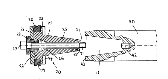
Figure 2 illustrates a roll-ring mount 20 constructed in
accordance with one embodiment of the invention, a roll-
ring 30 fitted to the mount, and a roll-axle 40 in which
one end of the mount 20 can be fitted.
The mount includes a body 21 having a first, cylindrical
end 22 on which the roll-ring 30 can be mounted with a
frictional fit, a collar 23 provided with an abutment
surface 24 for abutment with a roll-ring fitted on the
mount, and a second, conical end-part 25. Extending
through the body 21 is a central bore 26 which has a
constant diameter along the major part of the conical
end-part 25 of said body 21 and then widens to a larger
diameter, this larger diameter of said bore extending
along the whole of the first end-part 22. This region of
larger diameter of said bore 26 is screw-threaded. A
hollow screw 28 having an external screw-thread comple-
mentary to the screw-thread of the widened part of the
bore 26 is operative to firmly hold a clamping disc 27.
The hollow or hole through the screw 28 has the same
diameter as that part of the bore 26 extending along the
conical end-part of said body, and is in line with this
part of said bore. A bolt 29 is insertable through the
~32 ~ 7 ~
hollow in the screw 28 and through the bore 26. When the
bolt 29 is inserted, a screw-threaded part 31 of the
bolt extends beyond the end surface of the conical end-
part 25 of the body 21.
In order to ensure that the bolt 29 will be centered
when inserted into the bore, the roll-ring mount will
also preferably include two semi-circular guide plates
32,33 which encircle the stem of the bolt.
Figure 2 also shows one end of a roll-axle 40 which, in
accordance with the invention, includes a cavity 41,
whose shape is complementary with the shape of the
conical-end part 25 and in the bottom of which there is
provided a screw-threaded hole 42 into which the screw-
threaded end 31 of the bolt 29 can be screwed. The
screw-threaded hole is preferably provided in said end
of the roll-axle by means of an internally screw-thread-
ed sleeve which is inserted in and secured in the bottom
of the cavity 41 in some suitable manner.
The outer end of the roll-axle is configured with two
diametrically opposed pegs 43 which when the roll-ring
mount 20 is inserted into the cavity 41 engage comple-
mentary grooves 34 or recesses ormed-in the collar 23.
According to the invention, the roll-ring is prefitted
to the roll-ring mount. Thus, the work of fitting a
roll-ring to a roll-axle simply entails the insertion of
the mount 20 into the cavity 41 followed by tightening
of the bolt 29, subsequent to having first dismantled a
previously fitted mount, when necessary. The inventive
method thus enables a roll-ring change to be carried out
very quickly, thereby greatly reducing the idle time of
a rod mill occasioned by replacement of a roll-ring. The
inventive method also provides the advantage of enabling
roll-rings to be fitted to roll-ring mounts in any de-
sired workshop location and over any period of time,
without needing to subject the fitter to stress, thereby
enabling the roll-rings to be fitted to a high degree
accuracy and with the aid of special equipment if so
required, and by one skilful person or a few skilful
persons.
As will be evident from the following, the roll-ring can
be fitted in conjunction with the final or subsequent
working of roll-rings.
A roll-ring 30 is fitted to the roll-ring mount
described with reference to Figure 2 preferably in the
following manner. The roll-ring 30 is first threaded
onto the cylindrical end-part 22 of the body 21, where-
after the screw 28 with the clamping-plate 27 fitted
thereon is screwed into the screw-threaded hollow of the
end-part 22. The conical end-part 25 of the body 21 is
then inserted into a recess whose shape corresponds to
the shape of the recess 41 of the roll-axle 40, said
recess being configured in an anvil device or like
counter-pres6ure device. An appropriate press-tool
operative to exert pressure against the periphery of the
clamping-plate 27 is then activated and a predetermined
pressure is
applied to the clamping plate, and therewith also to the
mount. The screw 28 is then screwed into abutment with
the clamped clamping-plate, so as to hold the plate in
its clamped position. The press-tool is then removed and
the assembly comprising the body 21, the clamping
arrangement 27, 28 and the roll-ring 30 is removed from
the cavity in said anvil device. The bolt 29 i5 then
inserted into said assembly and the semi-circular guide-
plates 32,33 are fastened to the end of the conical end-
part 25 of the body 21. As shown in Figure 2, the threa-
~3i3~
,
ded bolt-end 31 has a slightly larger diameter than the
bolt-stem, and hence the guide plate 32, 33 will prevent
the bolt 29 from falling out of the mount. It will also
be seen that when removing a roll-ring mount from a roll
shaft, the outer screw-thread of the bolt-part 31 will
exert an outwardly directed force on the body 21 as the
bolt is unscrewed, therewith ensuring that the mount
will loosen from the roll axle.
As will be understood, it is also possible to insert the
bolt 29 and secure the guide plates 32, 33 prior to
applying the press tool, although this involves the
additional steps of screwing-in and unscrewing the bolt
29 when the cavity in the anvil device includes a screw-
threaded hole corresponding to the screw-threaded hole
42 of the roll axle. This variant is suitable, however,
when the roll-ring is to be finally machined after being
fitted and the anvil device consists of the shaft of a
machine tool, preferably a grinding machine, since the
bolt 29 then need only be tightened upon completion of
clamping the roll-ring in order for the roll-ring to be
fitted to the tool.
In this connection it should be observed that roll-rings
are normally re-ground a number of times during their
useful life, and consequently it is of significant
advantage that the inventive roll-ring mount is con-
figured in a manner which enables the mount to be fitted
to conventional grinding machines and that the roll-ring
can be re-ground without needing to remove the ring from .-
the mount.
It is, of course, also possible to clamp the roll-ring
without the aid of a press tool, by tightening the screw
28 to a predetermined torque setting.
~32~
Thus, the invention provides a method which enables
roll-rings to be replaced very quickly and simply,
without requiring the need for expert personnel to
effect such replacement. The component~ forming part of
the roll-ring mount by means of which the method is
carrying out are of simple construction and can be
manufactured without high demands on precision in manu-
facture.
It will be understood that the described roll-ring mount
merely constitutes a preferred embodiment of the inven-
tion and that the mount can be modified in several ways
within the scope of the invention, particularly with
respect to its clamping arrangement and the arrangement
by means of which the mount is non-rotatably fastened to
the end of a roll axle. It will also be understood that,
for instance, it is not necessary to configure the mount
so that it can be fitted directly to a machine tool,
since the mount can be configured so as to enable it to
be attached to a machine tool with the aid of a suitably
constructed coupling device, and it will also be obvious
that the constructional detail of the illustrated roll-
ring mount is not restricted to carrying out the inven-
tive method. Consequently, the invention is only limited
by the subject matter of the following claims.