Note: Descriptions are shown in the official language in which they were submitted.
CA 02032252 2002-02-28
TITLE
DUPLEX BAG HAVING
A HANDLE AND METHOD OF MAKING SAME
10
BACKGROUND OF THE INVENTION
Scope of the Invention
The present invention is directed to a bottom loaded or side loaded duplex bag
having a handle. Also disclosed is a method for making the bag.
Background of the Invention
U.S. Patent No. 1,808,375 discloses a shopping bag. The shopping bag has a
front
and rear panels which are joined together by a handle portion. The lateral
side
edges and bottom are joined together.
U.S. Patent No. 3,580,486 discloses a plastic bag having an integral strap-
like
handle at its upper end and a bottom gusset or satchel bottom. The gusset
unfolds
under the weight of the items carried in the bag.
CA 02032252 2002-02-28
_ 2 _
U.S. Patent No. 4,573,203 discloses a plastic bag having a gusset located at
its
upper most end adjacent a loop handle. The loop handle is welded to the bag
adjacent the upper edge portion of the bag.
Summar~of the Invention
The present invention is directed to a duplex bag having a handle. The bag
includes an inner and outer web of thermal plastic material. The outer web
includes a front panel, a rear panel and a handle portion. The handle portion
is
integral with the front and rear panels and has a width less than the width of
the
front and rear panels. The inner web includes a front panel, a rear panel and
a
gusset portion. The gusset portion is integral with the front and rear panels
and has
a line of perforations spaced from and parallel to the front and rear panels.
All
panels have about the same dimensions. The handle portion and the gusset
portion
are adjacent one another at a top end of the bag. The front panel of the outer
web
overlies the front panel of the inner web, and the rear panel of the outer web
overlies the rear panel of the inner web. A side seam is formed at each
lateral edge
portion of said front and rear panels and seals the panels together.
After the bag is filled, a bottom seam is formed at a bottom edge portion of
the
panels which seals the panels together. Additionally, a lip having a plurality
of
wicket holes may be located at the bottom edge portion of the bag. The lip
having
holes is used for holding the bag prior to filling and formation of the bottom
seam.
The present invention is also directed to a duplex bag comprising an inner bag
for
containing the product and an outer bag supporting the inner bag. The inner
bag
comprises opposing panels and at least one fold portion connecting the
opposing
panels. The outer bag comprises opposing panels and at least a handle portion
connecting the opposing panels. As used herein, "handle" has its customary
broad
meaning and refers not only to a loop handle through which a person may slip
an
arm to carry the duplex bag of this invention but also to other means which
one can
CA 02032252 2002-02-28
-3-
grasp for the purpose of carrying the bag; for example, a portion of plastic
with
holes, openings, or surfaces which fingers can grasp. The handle portion of
the
outer bag straddles a fold portion of the inner bag and provides support for
the
inner bag, and the inner and outer bags have substantially co-extensive
openings to
facilitate introduction of product into the inner bag. The duplex bag of the
invention is also directed to a duplex bag in which the four opposing panels
of the
inner and outer bags are sealed together along at least one common edge
portion of
the panels.
The present invention is also directed to method of making a duplex bag. In
one
method of this invention a thermal plastic web is provided for an inner bag
and at
least one fold is provided in the web for the inner bag. A thermal plastic web
is
also provided for an outer bag and at least one fold is provided in the web
for the
outer bag, and a handle is formed in one fold portion in the outer web. The
folded
inner web and the folded outer web are then joined such that the inner web
forms
an inner bag with an open end portion and the outer web forms an outer bag
with
an open end portion, the handle portion of the outer web straddling the fold
portion
of the inner web.
Description of the Drawings
For the purpose of illustrating the invention, there is shown in the drawings
forms
which are presently preferred; it being understood, however, that this
invention is
not limited to the precise arrangements and instrumentalities shown.
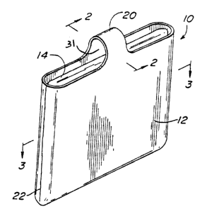
Figure 1 is an isometric view of a preferred embodiment of the present
invention.
Figure 2 is a sectional view of the bag shown in Figure 1 taken generally
along
sectional lines 2-2.
Figure 3 is a sectional view of the bag shown in Figure 1 taken generally
along
lines 3-3.
CA 02032252 2002-02-28
-4-
Figures 4-6 schematically illustrate the formation of an inner web in one
preferred
process of the invention.
Figures 7-9 schematically illustrate the formation of an outer web in one
preferred
process of the invention.
Figure 10 is an isometric view of a preferred embodiment prior to welding the
lateral seams.
Figure 11 is an isometric view of a preferred embodiment: prior to filing and
formation of the bottom seal.
Figure 12 is a sectional view of an alternate embodiment of the present
invention.
Figure 13 is a sectional view of another alternate embodiment of the present
invention.
Figure 14 is a view of another preferred embodiment of the present invention.
Figures 15 to 18 are sectional views of the bag shown in Figure 14 taken
generally
along sectional lines 15-15, 16-16, 17-17, and 18-18 respectively.
Figure 19 is an isometric view of the preferred embodiment of Figure 14 when
filled with product.
Figures 20 and 21 are sectional views of the bag shown in Figure 19 taken
generally along sectional lines 20-20 and 21-21 respectively.
Figure 22 is a view of another preferred embodiment of the present invention.
CA 02032252 2002-02-28
-5-
Figures 23 to 26 are sectional views of the bag shown in Figure 22 taken
generally
along sectional lines 23-23, 24-24, 25-25 and 26-26 respectively.
Figure 27 is an isometric view of the preferred embodiment of Figure 22 when
filled with product.
Figures 28 and 29 are sectional views of the bag shown in Figure 27 taken
generally along sectional lines 28-28, 29-29 respectively.
Detailed Description of the Invention
Referring to the drawings where like numerals indicate like elements, there is
shown in Figure 1 a preferred embodiment of the duplex bag generally
designated
10.
Duplex bag 10 comprises an inner web 14 and an outer web 12. Outer web 12
includes a handle portion 20. Inner web 14 preferably includes a gusset 16. A
line
of perforations 18 is preferably fornied at the apex of gusset 16. The line of
perforations 18 may be severed whereby materials within bag 10 may be
retrieved
or inserted.
The webs 12 and 14 are made of thermal plastic material which is weldable.
Webs 12 and 14 are welded together at lateral seams 22 and bottom seam 24.
Seams 22 and 24 may be formed in any conventional manner such as but not
limited to thermal welding, ultrasonic welding, electronic welding, etc. The
seams
and joints described herein may be glued, but this is not preferred.
The outer web 12 may be made of low millage material. Regardless of the low
millage material, the bag is still strong. The formation of creams 22 and 24
about
the periphery of the bag 10 allows the stress at the joining points of the
handle 20
and panels of web 12 to be evenly distributed over the entire web 12.
Accordingly,
CA 02032252 2002-12-04
-6_
the bag can be used for such heavy items as charcoal, fresh potatoes, diapers
or sanitary
products, garden products, etc.
Referring to Figures 4-6, the formation of inner web 14 is explained. Web 14
is
generally formed from a continuous web of thermal plastic material. The line
of
perforation 18 may bifurcate web 14 along the longitudinal axis. The web 14 is
then
folded over onto itself along the line of perforations 18. See Figure 5.
Alternately, a
plurality of wicket holes 26 may be disposed along a lateral edge portion or
lip of web 14
parallel to the line of perforations 18. Wicket holes 26 are used for holding
the bag during
loading. If the wicket holes 26 are used, then the line of perforations is
offset from the
longitudinal axis and the web 14 is folded at the line 18 whereby a lip having
the wicket
holes 26 is formed.
After web 14 has been folded over on itself as shown in Figure 5, gusset 16 is
preferably
formed along a line of perforations 18 at the folded portion of the bag. The
line of
perforations 18 is located along the apex of gusset 16.
2o Referring to Figures 7-9, the formation of outer web 12 is disclosed. Web
12 is formed
from a continuous strip of thermal plastic material. See Figure 7. Web I 2 is
folded over
onto itself along the longitudinal axis or can be folded over folded web 14,
so as to form
a gap 31 between the handle 20 and the folded portion of the web 14. See
Figure 8.
Handle 20 is formed along the folded portion of web 12 preferably by
diecutting. Of
course other methods may be used for forming the handle 20.
Referring to Figure 10, there is an illustration of the orientation of the
outer web 12 and
the inner web 14 immediately prior to the welding/lateral seam formation
operation. While
the inner and outer webs are shown in Figure 10 to be exactly co-extensive, as
mentioned
above it is sufficient if they are substantially co-extensive. For example, in
order to
facilitate use of wicket holes, to utilize certain printing equipment, or for
other reasons,
the inner and outer webs may be off set as much as is necessary to achieve
desired
purposes.
CA 02032252 2002-12-04
_ 7 _
Longitudinal welds 33 and 35 are preferably made adjacent an opening 38 of bag
10.
Weld 33 joins front and top panels 30, 34. Weld 35 joins rear and bottom
panels 32,
36. Welds 33, 35 are made in any well known manner. Welds 33. 35 prevent
materials, added to bag 10 during loading, from falling between the panels of
the
inner and outer panels.
Web 12 includes a front panel 30 and rear panel 32 which are joined together
by
to handle portion 20. Front panel 30 and rear panel 32 are preferably
rectangular and
have the same general dimensions. The handle portion 20 has a width which is
preferably narrower than the width of the front and rear panels 30 and 32.
Inner web 14 comprises a front panel 34, a rear panel 36 and the gusset
portion 16.
Gusset portion 16 is integral with and joins front and rear panels 34 and 36.
Front and
rear panels 34 and 36 are preferably rectangular and have the same general
dimensions.
Front and rear panels 30 and 32 and front and rear panels 34 and 36 all
preferably
2o have the same general dimensions.
Front panel 30 overlies front panel 34. Rear panel 32 overlies rear panel 36.
Handle
portion 20 and gusset portion 16 are separated by the gap 31.
Lateral seams 22 are formed along seam line 28. Seam line 28 is generally
perpendicular to perforated line 18. The welding operation which forms lateral
seams
22 severs one bag 10 from the next and seals the panels 30, 34, 36 and 32
together.
Figure 11 shows a preferred embodiment of the present invention prior to the
3o formation of a bottom seam 24. Bag 10 includes a bottom opening 18.
Materials are
filled into bag 10 via opening 38. If the embodiment having the lip and wicket
CA 02032252 2002-02-28
_g_
holes 36 is utilized, then during the formation of the bottom seal 26 the lip
is
severed from the bag 10.
Figures 12 and 13 illustrate two alternate embodiments of the present
invention in
which a closure means SO is attached adjacent to the gusset 16. The closure
means
50 includes a male member 52 and a female member 54. The male and female
members 52, 54 may be joined together thereby forming a seal which closes the
bag. Male and female members 52, 54 may be separated thereby allowing access
to the bag. Male member 52 includes a longitudinal rib 56 which is adapted for
a
press-lock fit in a groove 58 of female member 54.
The embodiment illustrated in Figure 12 has the closure means 50 straddling
perforated line 18. The male member 52 is welded to a portion of the gusset 16
on
one side of line 18 and female member 54 is welded to a portion of the gusset
16
on the other side of line 18. After the bag 10 is loaded and opening 18 is
sealed,
the closure means 50 can be opened and perforated line 18 separated. This
allows
access into the bag. The closure means 50 can be sealed., thereby closing the
bag.
The method of making the bag illustrated in Figure 12 is generally the same as
discussed above. However, the closure means 50 may be joined to the inner
20 web 14 prior to the first folding step. (See Figure 4a). The male and
female
members 52, 54 are joined to web 14 on either side of the perforated line 18
in any
conventional manner.
The embodiment illustrated in Figure 13 is generally the same as the
embodiment
of Figure 12. However, the closure means 50 (the same as previously described)
is
adjacent the front (or rear) panel. The perforated line 18 is eliminated and
new
perforated line 18' is formed. One member of the closure: means 50 is welded
to a
side 17 of gusset 16. The other member of the closure means 50 is welded to
the
panel of the inner web and is between panels of the inner and outer web. The
method of making this embodiment is generally the same as the originally
CA 02032252 2002-12-04
described method. However, the closure means 50 may be joined to the inner web
after or with the formation of the gusset 16. (See Figure 6a).
The bag shown in Figures 14 to 21 has a handle for the outer bag generally of
the
kind shown in U.S. Patent 4,252,269. As with other bags of this invention one
can
make the inner web have properties that are appropriate for holding the
product, while
making the outer web have different properties that are appropriate for
supporting the
1 o product in the inner bag. In addition, the embodiment of Figures 14 to 21
eliminates a
problem with the bags of U.S. Patent 4,252,269. When bags of that patent are
filled,
stresses from the handle have a tendency to concentrate at the apex on the
side seams
where the center portion of the gusset meets the side. Since the outer bag web
for the
handle may be cut back from the side seams in the embodiment of Figures 14 to
21,
~ 5 those stresses do not form.
The bag of Figures 14 to 21 comprises an inner web 114 and an outer web 112.
The
webs are made of thermal plastic and welded together at lateral seams 122 and
bottom seam 124. The duplex bag formed generally as shown in Figures 4 to 10
2o except that, following the steps of U.S. Patent 4,252.269, the outer web
112 is sealed to
itself at 119. In this embodiment of the invention, the portion of the outer
web at "a"
(see Figure 14) is cut out from the outer web to the opposing panels 130 and
136. The
inner web is then folded inward at fold 118, and the outer web is folded
inward at
fold 119 to form a gripping surface handle 120 that facilitates carrying the
bag. The
25 outer web thus makes up a bag having opposing panels 130 and 136, and the
inner
web makes up an inner bag having opposing panels 132 and 134. The outer bag
handle 120 and handle piece 119A connect opposing panels 130 and 136 and
straddle
the folded portion 118 and 116 of the inner bag, comprising panels 132 and
134. The
handle portion (120 and 119A) of the outer bag is longer than the fold portion
(116
3o and 118) of the inner bag.
CA 02032252 2002-02-28
-10-
In Figures 14 to 21, weld 133 joins front panels 130 and 134, and weld 135
joins
rear panels 132 and 136. Product may then be introduced into the bag through
opening 138. In the embodiment of Figures 14 to 21 the web between opposing
panels is sealed to itself at 119 to create two handle portions 120 and 119A.
The
handle 120 portion may be provided with an opening 121 to facilitate gripping
and
carrying the bag. If the distance "a" shown in Figure 14 is about one-half the
distance of the fold portion 116 between its opposing panels, when the bag 110
is
filled the first part of handle portion will cover most of the top portion of
the inner
bag.
The bag of Figures 22 to 29 has the advantage of no filling seam on the bottom
(the
side opposite the handle). The only seams on the bottom or otherwise taking
the
stresses of carrying are seams made under controlled conditions at the time of
or
before manufacture of the bag, and such seams are stronger than seams made at
the
time of filling and packing. 'This provides better strength and weight
carrying
properties. The bag of Figures 22 to 29 comprises an firmer web 214 and an
outer
web 212. The webs are made of thermal plastic, formed into individual tubes at
a
seam not shown, and welded together at lateral seam 222.. The duplex bag is
formed generally as shown in Figures 4 to 10 except that they are formed into
tubes
with no opening in the area of welds 33 and 35. The inner web is folded inward
at
fold 218, and the outer web is formed into handle 220 that facilitates
carrying the
bag. The outer web thus makes up a bag having opposing panels 230 and 236, and
the inner web makes up an inner bag having opposing panels 232 and 234. The
outer bag handle 220 connects opposing panels 130 and 136 and straddle the
25 folded portion 218 of the inner bag, comprising panels 232 and 234. During
manufacture of the bag only one side seam (222) is sealed and the opposite
side is
left open to facilitate filling with product. Once filled, this opening 238 is
closed
and sealed to form seam 223.
30 The duplex bags of this invention may be manufactured at high speed on
automatic
machinery. Because of t:he use of two layers and the stre;>s distribution
properties
CA 02032252 2002-02-28
-11-
of the design, savings :in raw materials are possible while at the same time
permitting flexibility in packaging and the possibility of additional
features. For
example, a vacuum may be drawn on the inner bag, coupons may be placed
between layers of the bag, and the inner web may have breathing holes for
fresh
5 produce without sacrificing strength in the outer supposing bag. The
flexibility of
this invention also permits the inner bag to have, for example, a reclosure as
a
convenience to the purchaser.
A variety of perforation and opening arrangements is possible. In addition to
the
closure means of Figures 12 and 13, pressure sensitive tape or other
recloseable
sealing means may be used. Such recloseable means may be placed anywhere on
the inner bag as may suit the product, and perforations rnay be arranged to
provide
primary seals that are tamper evident in the store but cover secondary seals
(such as
in Figures 12 and l3) which may be used by the purchaser at home for
reclosure.
Perforations may be placed on the folds 16, 116 and 216, as illustrated, but
also in
the side, front, or back panels. Perforations on the inside bag may be offset
with
respect to perforations on the outside bag and thereby provide both protection
of
the product and a degree of access to the product by manipulating a hand
through
two non-aligned openings without permitting the contents to fall freely from
the
20 bag.
Sealing patterns may also be varied. While the bags described above are shown
with continuous seals at seams between the inner and outer webs, spot sealing
elsewhere on the panels to increase dimensional stability or registration of
the two
bags is also contemplated. The inner bag may have vents for fresh produce, to
permit out-gassing, and/or to reduct trapped air. While continuous seals for
the
seams are shown, it will be understood that there may be circumstances where
partial seals may be advantageous. Additionally, access to the space between
the
inner and outer bags may be arranged so that the bag can receive and carry
30 additional items, such as coupons inserted by the manufacturer of the goods
packaged in the bag, or bottles or other items inserted by the purchaser of
the bag
CA 02032252 2002-02-28
-12-
after the bag has been opened. Verticle and other seals between the inner and
outer
bags can create pockets for receiving such items, which facilitate this use.
While the handle is shown in some figures without cut-outs, cut-outs to
facilitate
gripping may be used. Similarly, the width and the length of the handle may be
varied to suit the user. We contemplate, for example, a handle that can be
slipped
over the arm either along the long axis of the package (as shown in Figure 1)
or,
because of additional holes, finger grips, or the like at right angles to that
axis.
The present invention may be embodied in other specific forms without
departing
from the spirit or essential attributes thereof and, accordingly, reference
should be
made to the appended claims, rather than to the foregoing specification, as
indicating the scope of the invention.