Note: Descriptions are shown in the official language in which they were submitted.
CA 02032290 1999-08-OS
VIDEO TAPE RECORDER WITH AUDIO ARRIER AR~FNCE DETECTTnt~
BACEGROUND OF THE INVENTION
Field of the Invention
The present invention generally relates to video tape
recorders and, more particularly, to a video tape recorder such
as an 8-mm video tape recorder for recording and/or reproducing a
stereo FM (frequency modulated) audio signal.
Description of the Prior Art
In a so-called 8-mm video tape recorder (i.e. 8-mm VTR), a
stereo audio signal is originally recorded and reproduced in a
digital fashion, and an FM audio signal is recorded and
reproduced in a monaural fashion. However, in the later stage,
it is requested to record and reproduce this FM audio signal in
stereo mode.
In the 8-mm video tape recorder, an FM audio signal is made
stereophonic as, for example, shown in Fig. 1 (formed of Figs. lA
and 1B drawn on two sheets of drawings to permit the use of a
suitably large scale).
More specifically, as shown in Figs. lA and 1B, stereophonic
left and right audio signals L, R or main and sub audio signals
M, S are supplied to input terminals 1L, 1R, respectively. In
this case, the left or main audio signal L or M is supplied to
the input terminal 1L and the right or sub audio signal R or S is
supplied to the input terminal 1R.
Signals from these input terminals 1L, 1R are supplied to
terminals L, R of a matrix circuit 2. Thus, from the matrix
circuit 2, signals LZR and LZR are delivered to its respective
terminals.
The signal L2R from this matrix circuit 2 and the main audio
signal M from the input terminal 1L are selected by a switch 3M,
~ ~, G~, ..., n~ r,
and the signal L2R from the matrix circuit 2 and the sub audio
signal S are selected by a switch 3S. Then, the signals selected
by the switch 3M are supplied to an FM modulator 5M through a
noise cancelling encoder 4M and modulated on a first carrier
signal of 1.5 MHz. Also, the signals selected by the switch 3S
are supplied to an FM modulator 5S through a noise cancelling
encoder 4S and modulated on a second carrier signal of 1.7 MHz.
These modulated signals are supplied to a mixer 6.
Further, a composite video signal is supplied to an input
terminal 7, and the composite video signal from the input
terminal 7 is supplied to a luminance/chroma signal (Y/C)
separating circuit 8. Separated luminance signal and chroma
signal are supplied to input terminals 9Y and 9C, respectively.
-~;-~,=~r~ The luminance signal Y separated by the separating circuit 8 and
the luminance signal from the input terminal 9Y are selected by a
switch 10Y, while the chroma signal separated by the separating
circuit 8 and the chroma signal from the input terminal 9C are
selected by a switch lOC. Further, the signal selected by the
switch l0Y is supplied to a luminance signal recording and
processing circuit 11Y, and the signal selected by the switch lOC
is supplied to a chroma signal recording and processing circuit
lle.
. Then, the signals thus processed by these recording and
processing circuits 11Y and 11C and the signal from the above-
mentioned mixer 6 are mixed by a mixer 12. Further, this mixed
signal is supplied to a magnetic head 13 and recorded on a
magnetic tape 14. The recording is performed in this way, while
a reproduction is performed as follows.
More specifically, a signal recorded on the magnetic tape 14
2
,.: , .
is reproduced by the magnetic head 13. This reproduced signal is
supplied to a luminance signal reproducing and processing circuit
15Y and a chrome signal reproducing and processing circuit 15C.
A luminance signal Y and a chrome signal C, respectively
processed thereby for reproduction, are delivered to output
terminals 16Y and 16C, and also supplied to a mixer 17. The
mixed composite video signal therein is delivered to an output
terminal 18.
Further, the reproduced signal from the magnetic head 13 is
supplied to a 1.5 MHz bandpass filter 19M which derives the
signal components modulated on the above-mentioned first carrier
signal of 1.5 MHz. The signal thus derived from the bandpass
filter 19M is supplied to an FM demodulator 20M, in which it is
FM-demodulated to provide the above-mentioned signal L2R or the
main audio signal M. The demodulated signal is supplied to a
noiso cancelling decoder 21M.
Also, the reproduced signal from the magnetic head 13 is
supplied to a 1.7 MHz bandpass filter 19S which then derives the
signal component modulated on the above-mentioned second carrier
signal of 1.7 MHz. The signal derived from the bandpass filter
19S is supplied to an FM demodulator 20S, in which it is FM-
demodulated to provide the above-mentioned signal L2R or the sub
audio signal S. The demodulated signal is supplied to a noise
cancelling decoder 21S.
The signals from these decoders 21M and 21S are supplied to
respective terminals of a matrix circuit 22, in which
the above-mentioned signals L2R and L2R are processed to
provide left and right audio signals L and R which are then
3
- b ., ~ '~ G '. (''r /1 ~~ !\
F~: ,~' ._ ;~.7 i,n e.%,1
delivered to respective treminals for signals L and R.
The left audio signal L from this matrix circuit 22 and the
main audio signal M from the decoder 21M are selected by a switch
23L and delivered to an output terminal 24L, and also the right
audio signal R from the matrix circuit 22 and the sub audio
signal S from the decoder 21S are selected by a switch 23R and
delivered to an output terminal 24R.
Therefore, in this circuit of Fig. 1, the audio signals
supplied to the input terminal 1L and 1R are converted to so-
called sum signal and difference signal in the case that they
are stereophonic left and right audio signals L and R, where the
sum signal is transmitted by the first carrier signal while the
difference signal is transmitted by the second carrier signal.
On the other hand, when the main and sub audio signals M and S
,a
;~.~ f..r;~
~ are supplied to the input terminals 1L and 1R, the main audio
signal M is transmitted by the first carrier signal and the sub
audio signal S is transmitted by the second carrier signal.
That is, in the FM audio signal recording of the so-called
8-mm video tape recorder, the second carrier signal is added to
the indispensable first carrier signal. For this reason, to
maintain compatibility with conventional apparatus having only
the first carrier signal, the sum signal and the main audio
signal are transmitted by the first carrier signal while the
w difference signal and the sub signal are transmitted by the
second carrier signal, as described above.
Incidentally, in the 8-mm video tape recorder, the frequency
of the first carrier signal is determined to be 1.5 MHz with a
maximal frequency deviation of ~ 100 kHz, and the frequency of
the second carrier signal is determined to be 1.7 MHz with a
maximal frequency deviation of ~ 50 kHz. Regarding a recording
4
current, the second carrier signal is set to -2 ~ 4 dB as
compared with the first carrier signal.
Incidentally, in the above-mentioned 8-mm video tape
recorder, even if a video tape on which an FM audio signal is
recorded in stereophonic mode is reproduced by a conventional
video tape recorder exclusively used in the monaural mode, a
reproduced signal can be obtained without trouble because the sum
signal of the left and right audio signals is reproduced.
However, if a conventional monaurally recorded video tape is
reproduced by a video tape recorder which can reproduce the audio
signal in the stereophonic mode, high level noises are generally
generated from the FM demodulator 205, and if these noises are
supplied to the matrix circuit 22, resultant left and right audio
signals axe mixed with the noises of high levels so that the
'' . I''~ ~ normal reproduction cannot be made .
Therefore, conventionally, as for example shown in Fig. 2, a
filter output from the 1.7 MHz bandpass filter 19S is supplied to
a level detector 25, and this detected output is supplied to a
comparator 26, wherein the presence of the second carrier signal
is determined (a determined output is delivered to an output
terminal 27) when the level of the filter output is above a
predetermined value.
However, this method is easily affected by the changes in
level of reproduced signal from the magnetic head 13, and an
erroneous decision may easily occur. Also, a malfunction may be
incurred by disturbing waves. For example, if a lower side band
of the luminance signal Y, which is FM-recorded, existed in the
vicinity of 1.7 MHz in a high level, there is then the risk that
the presence of the second carrier signal would be determined
regardless of the absence of the second carrier signal.
~~,, ,-~, r-, i~ ;o .: y (';.
7Y: x: w , ,.~ 9 > 'J
OBJECTS AND SUMMARY OF THE INVENTION
Accordingly, it is an object of the present invention to
provide an improved video tape recorder which can eliminate the
aforenoted shortcomings and disadvantages encountered with the
prior art.
More specifically, it is an object of the present invention
to provide a video tape recorder which can be protected from
being affected by the change of level of a reproduced signal from
a magnetic head.
It is another object of the present invention to provide a
video tape recorder which can be prevented from being
malfunctioned due to the mis-detection of a disturbing wave.
According to an aspect of the present invention, a video
tape recorder for recording and/or reproducing a stereo
frequency-modulated audio signal by a pair of carrier signals of
an indispensable first carrier signal and an additional second
carrier signal is comprised of a circuit for demodulating the
second carrier signal to provide a demodulated output, and a
circuit for comparing an amplitude of the demodulated output with
a predetermined value, wherein when the amplitude of the
demodulated output is below the predetermined value, it is
determined that the second carrier signal exists.
The above, and other objects, features and advantages of the
present invention will become apparent in the following detailed
description of an illustrative embodiment thereof to be read in
conjunction with the accompanying drawings, in which like
reference numerals are used to identify the same or similar parts
in the several views.
BRIEF DESCRIPTION OF THE DRAWINGS
Fig. 1 (formed of Figs. lA and 1B drawn on two sheets of
6
~. : .
. . ,:~; :.. .. . , '~ ~...
drawings to permit the use of a suitably large scale) is a block
diagram showing an example of a signal system of a so-called 8-mm
video tape recorder. to which the present invention is applied;
Fig. 2 is a schematic block diagram showing a circuit
arrangement of the prior art; and
Fig. 3 is a schematic block diagram showing an embodiment of
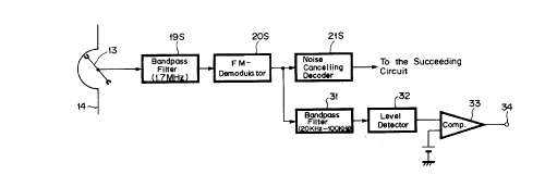
a video tape recorder according to the present invention.
DETAILED DESCRIPTION OF THE PREFERRED EMBODIMENT
An embodiment of the video tape recorder according to the
present invention will now be described hereinafter with
reference to Fig. 3. In Fig. 3, like parts corresponding to
those of Figs. 1 and 2 are marked with the same references
and therefore need not be described in detail.
Referring to Fig. 3, the demodulated output from the FM
demodulator 20S is supplied to a bandpass filter 31 of, for
example, 20 kHz to 100 kHz, and the filter output of the bandpass
filter 31 is supplied to a level detecting circuit 32. A level
detected output from the level detecting circuit 32 is supplied
to a comparator 33, and compared output therefrom is delivered to
an output terminal 34.
More particularly, in the above-mentioned 8-mm video tape
recorder, when the FM demodulation is performed normally, the
output from the FM demodulator 20S to demodulate the second
carrier signal has the following features:
(1) The frequency spectrum of the demodulated signal is limited
within a demodulating frequency band (e. g., lower than 20 kHz);
and
(2) The output amplitude is limited below a fixed value as
follows:
(signal component) + (undesired components associated with
7
m:.,. ,.., L ~., ; n s ~. ~~. !,,
.:. .~c 1j.:1 "V.~ '~_i
carrier signal)
where the signal components are limited below a maximal frequency
deviation in the recording system.
The undesired components associated with the carrier signal
area frequency components twice the carrier frequency and so on
and are below the fixed value which is determined depending on
circuits.
Accordingly, when these conditions are not satisfied, it may
be determined that the second carrier signal does not exist.
Therefore, in the above-mentioned circuit, components within
the modulating frequency band and the undesired components
associated with the carrier signal are removed by the bandpass
filter 31, and this filter output is converted into a direct
current voltage by a level detector 32. A level detected output
~:~-a;: a
is then compared with a reference voltage by the comparator 33 to
determine that the second carrier signal exists when this voltage
is below the reference voltage. The decided output can be
delivered to the output terminal 34.
Thus, according to the above-mentioned circuit, the
amplitude of an FM demodulated signal is detected to determine
whether or not the the second carrier signal exists so that the
decision of the second carrier signal can be prevented from being
affected by the changes in level of reproduced signals from the
magnetic head, and malfunction due to an erroneous detection of
disturbing waves can be satisfactorily prevented.
Incidentally, in the above-mentioned circuit, depending upon
the characteristic of the 1.7 MHz bandpass filter 19S and the
characteristic of the FM demodulator 205, even if the bandpass
filter 31 is simplified by a high-pass filter and a trap circuit
or omitted, it is possible to sufficiently take a level
8
h~~ .. , tr..~ (..,~ t ~ ~°.l
difference due to the presence or absence of the second carrier
signal of the output amplitude from the FM demodulator 205.
As set out above, according to the present invention, since
the presence of the second carrier signal is determined by
detecting the amplitude of the FM demodulated signal, the
decision of the second carrier signal can be prevented from being
affected by the changes in level of the reproduced signal from
the magnetic head, and the malfunction due to the erroneous
detection of the disturbing waves can be favorably prevented.
Having described a preferred embodiment of the invention
with reference to the accompanying drawings, it is to be
understood that the invention is not limited to that precise
embodiment and that various changes and modifications thereof
could be effected by one skilled in the art without departing
from the spirit or scope of the novel concepts of the invention
as defined in the appended claim.
9