Note: Descriptions are shown in the official language in which they were submitted.
2Q~
I I :
Compensation of static and/or quasi-static magnetic fields
in magnetoelastic force and torque transducers
TECHNICAL FIELD
The present invention relates to a method and a device for
detecting and compensating for the effect of static and
slowly varying magnetic fields on devices intended to
measure mechanical stresses with the aid of the magneto-
elastic effect.
BACKGROUND ART, THE PROBLEM
The magnetoelastic effect is a phenomenon whereby the
magnetic permeability of a ferromagnetic material is changed
when it is subjected to mechanical stresses.
Utilizing the above-mentioned effect for measuring
mechanical forces and torques is an idea that arose over
fifty years ago. In recent years this idea has attracted an
increasingly greater interest.
Above all, the new amorphous materials with their very
powerful magnetostriction have contributed to this increase,
and also the possibility of using this technique for
measuring torques in a contactless and very simple manner.
In addition, transducers based on the magnetoelastic effect
are characterized by very high resistance with respect to
the external environment and by a high signal power and
hence low sensitivity to disturbance.
The design of the above-mentioned transducers varies
considerably, but, in principle, the following summary can
be made.
2Q32~$~
A body of a ferromagnetic material is subjected to a
periodic magnetization by allowing current to pass through
an excitation winding.
The most primitive concept then only measures the inductance
in the excitation winding in order thereby to obtain a
measure of the magnetic permeability of the material and
hence a measure of the mechanical stress.
More sophisticated devices make use of a secondary winding
for sensing the time rate of change of the induced magnetic
flux.
With the aid of a secondary winding, it is also possible to
measure the induced flux in a direction transverse to the
magnetization, and in a direction making an angle of 45~
with the principal stress direction of the mechanical
stresses in the loaded body. This is the case with the
known transducers PRESSDUCTOR ~ and TORDUCTOR ~.
Another frequently used measuring principle comprises
measuring the induced magnetic flux in several regions or
measuring zones which are subjected to different mechanical
stresses, and then forming the difference between these
fluxes.
The most common method is to use two measuring zones, one of
which is loaded with tensile stress and the other with
compressive stress in the direction of the magnetic field.
This is done, for example, in the patent specifications of
EP 0089916 and US 4506554.
Another method is to measure the difference between the
fluxes which are induced in a loaded and an unloaded zone.
Irrespective of which method is used in order to measure the
permeability change in the magnetoelastic material, the
magnetic hysteresis curve, i.e. the B-H curve which each
2~2.~
point in the material completes during a period of the
magnetization, will be changed when the material is
magnetized by a static field. This, of course, influences
the measurement of the induced fluxes and leads to ~hanglels
both of the measuring signal in an unloaded transducer, i.e.
the zero signal, and of the sensitivity of the transducer to
load.
If the transducer is magnetized by a static field to such an
extent that the ferromagnetic material approaches
saturation, the differential permeability and also the
sensitivity of the transducer will be very low. However,
the influence remains in connection with considerably lower
fields.
To reduce the influence of this disturbance, attempts have
been made to screen off external magnetic fields. However,
screening off static or slowly varying, i.e. quasi-static,
magnetic fields has proved to be a difficult technical
problem. This problem may be particularly difficult when
attempts are made to screen off such magnetic fields in
shafts in connection with the measurement of torques.
The problem with static external magnetization may become
particuarly serious since static magnetization, by remanence
in the transducer material, may give rise to permanent
changes in the function of the transducer.
The present invention suggests a method of protecting
against the effects of static and/or quasi-static magnetic
fields. In addition, the method provides information as to
when this protection, in spite of all, is not sufficient and
may warn that the transducer does not function
satisfactorily, which is very important when the transducer
is used in automatic control systems.
SU~ARY OF THE INVENTION
According to the present invention, there is provided a method
for detection of and protection against an effect of disturbing
static or quasi-static magnetic fields on measurement with a
force or torque transducer based on magnetoelastic effect,
which method assumes presence of such a transducer which is
magnetized by a symmetrical, periodic supply current, a Fourier
representation of which only comprises a fundamental frequency
and odd harmonics of this fundamental frequency, the method
being characterized in that when the transducer is supplied
with the current, a first signal proportional to a flux in the
transducer or its time rate of change is supplied to a first
input of a phase-sensitive detector, an output signal of which
is proportional to a content of even harmonics in the Fourier
representation of said first signal, or that when a
magnetization of the transducer is supplied with voltage, a
second signal proportional to the supply current which
magnetizes the transducer is supplied to a second input of the
phase-sensitive detector, an output signal of which is
proportional to a content of even harmonics in the Fourier
representation of this second signal, and that when the output
signal of the phase-sensitive detector is different from zero,
detection of disturbing static or quasi-static magnetic fields
is indicated.
According to the present invention, there is also provided a
device for detection of and protection against an effect of
disturbing static or quasi-static magnetic fields on
measurement with force or torque transducer based on a
magnetoelastic effect, the device comprising such a transducer
which is magnetized by a symmetrical, periodic supply current,
a Fourier representation of which only comprises a fundamental
frequency as well as odd harmonics of this fundamental
frequency, the device being characterized in that when the
transducer is supplied with the current, a first signal
4a
proportional to a flux in the transducer or its time rate of
change is supplied to a first input on a phase-sensitive
detector, an output signal of which is proportional to content
of even harmonics in the Fourier representation of this first
signal, or that when a magnetization of the transducer is
supplied with supply voltage, a second signal proportional to
the supply current which magnetizes the transducer is supplied
to a second input on the phase-sensitive detector, an output
signal of which is proportional to a content of even harmonics
in the Fourier representation of said second signal, and that
when the output signal of the phase-sensitive detector is
different from zero, the device is adapted to indicate
detection of disturbing static or quasi-static magnetic fields.
_ 4b ~ $
In general terms, as is well known, an arbitrary periodic
signal may be represented as a Fourier series, i.e. a sum of
sinusoidal signals with different phases but with
frequencies which are multiples of one divided by the period
of the periodic signal. The lowest of these frequencies is
called fundamental freqency or fundamental tone and the
others with frequencies which are multiples of this
fundamental frequency are called harmonics. Depending on
whether the frequency of a harmonic is one time, three times
or several times the fundamental frequency, reference is
made to the second tone, the third tone, etc., of the
periodic signal.
Now, the invention utilizes the fact that the B-H curve, in
case of normal magnetization without static fields, is
completely symmetrical with respect to reflection through
the origin of coordinates.
One way of expressing the above in mathematical terms is
that the magnetic flux density, i.e. the B-field, changes
signs after half a period, i.e.
B(t+T/2) = -B(t) (1)
where B = the magnetic flux density
t = the time
T = the period of the magnetization
If the magnetizing field, i.e. the H-field, is purely
sinusoidal, the above symmetry means that the Fourier
representation of the magnetic flux density as a function of
the time will only comprise a fundamental tone and odd
harmonics.
A completely linear material gives no harmonics at all,
whereas a saturated, non-linear material exhibits a very
2~3~
. ,.,~ s
high content of above all third tones but also of other
tones.
When a material has a static magnetization superimposed on
the sinusoidal, symmetrical magnetization, however, the
symmetry in the B-H curve, indicated by equation (1), is
broken. As a result, the Fourier representation of the B-
field as a function of the time will also comprise even
harmonics.
Accordingly, the invention comprises a method and a device
for determining the presence of even harmonics. Measuring
the content of these harmonics gives a measure of the degree
of static and/or quasi-static magnetization and the measured
value may be used as an input signal to a regulator which,
with the aid of a direct current, controls this external
magnetization to zero.
If the regulator is not able to compensate for the static
and/or quasi-static magnetic field, it limits and a warning
signal is obtained in a simple manner from the electronics.
A limit as to how rapidly the disturbing quasi-static
magnetic field disturbance is allowed to vary is given by
the demand that the disturbing magnetization is to change to
a small extent during a period of the periodic
magnetization.
To manage magnetization in different directions, it is
required that the phase position of the second tone relative
to the fundamental tone is kept track of. This is most
readily managed by phase-sensitive rectification at the
frequency of the second tone. This will be described in
more detail under the "Description of the Preferred
Embodiments".
6 2
BRIEF DESCRIPTION OF THE DRAWINGS
Figure 1 shows a symmetrical magnetic hysteresis curve as
well as a distorted curve when the material is magnetized by
a static magnetic field.
Figure 2 shows a block diagram of electric equipment
according to the invention which manages to detect the
external magnetization and control this to zero with the aid
of a compensating winding.
Figure 3 shows a modified block diagram of electric
equipment according to the invention which manages to detect
the external magnetization and control this to zero without
the help of a compensating winding.
Figures 4, 5 and 6 show three different embodiments of the
oscillator section in the block diagram according to Figures
2 and 3.
Figure 7 shows an embodiment of the phase-sensitive
detection of even harmonics in the block diagram according
to Figures 2 and 3.
Figure 8 shows the principle of applying a compensating
winding for preventing static and/or quasi-static magnetic
fields from disturbing a magnetoelastic force transducer.
Figure 9 shows the principle of applying a compensating
winding for preventing static and/or quasi-static magnetic
fields from disturbing a magnetoelastic torque transducer.
Figure 10 shows how the compensation may be solved without
extra windings according to Figure 3, in one case when the
direction of the expected disturbance of the magnetic field
coincides with the direction of the magnetizing periodic
field.
2 Q ~
DESCRIPTION OF THE PREFERRED EMBODIMENTS
The effect of the hysteresis curve and a static
magnetization on the harmonic content of the induced
magnetic B-field may be studied with reference to Figure 1,
in which curve "a" illustrates the symmetrical magnetic B-H
curve which is completed during one period and in which
curve "b" shows the distorted curve which is a result of the
material, in addition, being magnetized by a static magnetic
field. A sinusoidal magnetization according to curve "a"
gives a harmonic content in the B-field of 16% of a third
tone and 6% of a fifth tone. A sinusoidal magnetization
with a static magnetization which produces a curve according
to "b" has a second tone in the B-field of 18%.
A preferred embodiment of the method according to the
invention is shown in Figure 2 in the form of a block
diagram for electric equipment which prevents disturbing
static or quasi-static magnetic fields from influencing the
measurement of force or torque with a magnetoelastic
transducer.
The equipment comprises a voltage source which from its
outputs 2 and 3 delivers signals which are locked in
relation to each other and which have an exact frequency
ratio between the signals which is equal to two. The signal
from output 2 with the lowest frequency shall be symmetrical
around zero, completely free from even harmonics, and is
suitably given a pure sine shape, although a pulsewidth-
modulated square wave is also, in principle, possible. The
signal from the output 3 with double the frequency is also
to be symmetrical in such a way that the duration of the
half-periods is exactly the same.
The signal from output 2 is connected to a first amplifier 4
which feeds the excitation winding 5 of the transducer. The
amplifier may be connected so that the supply voltage is
~032S~
current-controlled according to the signal from output 2, or
it may be voltage-controlled according to the same signal.
The above two possibilities of supplying current permit two
different methods for detection of even harmonics.
If the exciting current is current-controlled, any even
harmonics may be detected in a voltage proportional to the
time rate of change of the flux, for example as the induced
voltage in a winding parallel to the excitation winding.
This voltage is supplied to a detector which, for detection
of even harmonics, is also supplied with the signal from the
output 3 of the voltage source, i.e. the signal with double
the frequency of the supply frequency.
If the magnetization supply to the transducer is voltage-
controlled, any even harmonics may be detected in a signal
proportional to the supply current, for example in the form
of the voltage across a shunt in the supply circuit. This
signal is supplied to a detector which, for the detection of
even harmonics, is also supplied with the signal from the
output 3 of the voltage source, i.e. the signal with double
the frequency of the supply frequency.
The above two methods entail that the content of even
harmonics will always be superimposed on the fundamental
tone. To obtain a better resolution of the phase-sensitive
detector, Figure 2 shows a preferred embodiment which means
that both the voltage proportional to the time rate of
change of the flux and the voltage proportional to the
exciting current are supplied to the detector. The first
one of these signals is supplied to input 6 and the second
signal is supplied to input 7 on the phase-sensitive
detector 8 for detection of even harmonics. The signal 6 is
obtained as the induced voltage in a winding 9 parallel to
the excitation winding.
A more detailed description of the phase-sensitive detector
will be given with reference to the description of Figure 7.
2 ~ ~ 2 ~ ~ ~
g
i.,.._,
Now, if the transducer is magnetized by a static and/or
quasi-static magnetic field, the B-H curve will be distorted
as shown in Figure 1 in such a way that even harmonics
arise. These harmonics have a definite phase position in
relation to the periodic magnetization. Since the detection
takes place in a phase-sensitive manner, various directions
of the static magnetization may be distinguished. The
signal from output 10 of the detector may therefore be
supplied to a regulator 11 which, with or withut a separate
compensating winding, generates an oppositely directed
static magnetic field and reduces the harmonic content of
even harmonics to zero.
In the embodiment described in Figure 2, the signal from the
output 12 of the regulator has been connected to a second
amplifier 13 which, in turn, drives a current through a
compensating winding 14 which generates the required
oppositely directed field.
In order to obtain a warning signal from the electronics if,
despite the compensating signal from the regulator and the
second amplifier, the supply is still disturbed by
superimposed static and/or quasi-static magnetization, the
signal from the output 10 of the detector is connected to a
level discriminator 15, whose signal from the output 16
constitutes the required warning.
Figure 3 shows an alternative embodiment of the compensation
process itself. The signal from the output 12 of the
regulator is added in the first amplifier to the signal from
the output 2 of the voltage source. In this way, the
periodic magnetization will contain a static and/or quasi-
static component which compensates for the external
disturbance.
If the cable resistance is low, the signal to the input 6 of
the detector, instead of being taken from the compensating
~032.~
winding 9, may be taken directly from the supply voltage of
the transducer.
If the transducer is supplied with sinusoidal supply voltage
and the output signal from the transducer does not change
signs when being subjected to load within the measuring
range, it is also, in principle, possible to use the output
signal of the transducer as a signal to input 6 of the
detector.
For certain transducer types, two or more measuring zones
with a measuring winding in each zone are used. These are
normally connected in opposition to obtain a difference
signal. By making the terminals of all measuring windings
available, also the total flux in the transducer may be
measured and such a sum signal is then also possible to use
as input signal 6 to the phase-sensitive detector.
The regulator 11 is suitably designed as an ordinary PI
regulator.
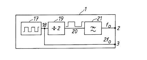
Figure 4 shows a method of realizing the voltage source 1 in
Figures 2 and 3. The starting-point is a digital frequency
generator 17. The output 18 is used directly as the
required control signal from the output 3 of the voltage
source, and it is also connected to the input of a frequency
divider 19. The signal from the output 20 of the frequency
divider 19 is thus a square wave with the frequency of half
the input signal. Finally, the square wave is filtered in a
low-pass filter 21 and is then connected to the output 2 of
the voltage source.
Figure 5 shows another principle for realizing the voltage
source with the aid of a sine generator 22. The output of
this generator is connected directly to the output 2 of the
voltage source and is also full-wave rectified in a
rectifier 23. This creates a signal which contains a
frequency component with double the frequency of the sine
2~32~
11
generator. The rectified signal is then filtered with the
bandpass filter 24 and then connected to the output 3 of the
voltage source.
Figure 6 shows a third alternative in which two sine
generators 25 and 26 are used, which are synchronized via a
connection 27.
Figure 7 shows an implementation of the phase-sensitive
detector 8 of even harmonics, shown in Figures 2 and 3. The
signal arriving at connection 6 is phase-shifted in a phase-
shift circuit 28 and passed from the output 29 to a
subtractor 30 where it is subtracted from the signal
arriving at connection 7 and being proportional to the
supply current. The signal level and phase position of the
output 29 of the phase-shift circuit are to be adapted such
that the signal on the output 31 of the subtractor contains
as small a portion as possible with the same frequency as
the magnetization of the transducer. The signal on the
output of the subtractor is connected to the input of a
phase-sensitive rectifier 32. The control signal to the
phase-sensitive rectifier is obtained by phase-shif~ling Ithe
signal from the output 3 of the voltage source in a phase-
shift circuit 33. The phase-shift is chosen such that the
phase of the control signal corresponds to the phase of the
second tone which arises in the signal on the output from
the subtractor when the transducer is subjected to a static
magnetic field. The signal on the output 34 from the phase-
sensitive rectifier is finally low-pass filtered in a low-
pass filter 35.
As previously described, it should be noted that it is not
necessary for the function of the detector to subtract the
fundamental tone from the voltage signal connected to input
6 and from the current signal connected to input 7,
respectively However, this method reduces the demands for
ideality of the phase-sensitive rectifier 32.
~ ~ ~ 3~
12
_
Other solutions for implementing the demodulator are, of
course, also possible.
In the solutions described above, the various functions have
been realized as building blocks designed on the basis of
analogue technique. However, there is, of course, nothing
preventing realizing the same functions with the use of a
digital signal processor.
Figure 8 shows a force transducer36 which is protected from
a static and/or quasi-static magnetic field with the aid of
a compensating winding 14. The force on the force
transducer is applied by way of an end piece 37 which is
also capable of conducting static magnetic fields into the
transducer. To prevent this, the compensating winding is
wound around the end piece. In addition, the transducer is
suitably screened off with the aid of a shielding box 38 of
highly permeable magnetic material. This protects the
transducer from external magnetic fields which are directed
across the direction of force. The screen also functions as
flux closure yoke for the magnetic field generated by the
compensating winding, which, in turn, reduces the current
consumption of the second amplifier 13 according to Figure
2.
Figure 9 shows how a torque transducer 39, with the aid of a
compensating winding 14, may be protected from a static
and/or quasi-static magnetic field which is introduced via a
torque-loaded shaft 40. It is shown here that the
compensating winding may be wound around the transducer
itself instead of around the shaft. Also in this case, an
external magnetic screen 41 may be used.
Figure 10 shows an example of how to proceed with a torque
transducer for compensation in accordance with the
embodiment illustrated in Figure 3. Figure 10 shows, in
cross section, the principle of a contactless torque trans-
duoer a~ ing to, for example, US patent 4,506,554. In this
,~ ~
2 ~ ~J ~
13
transducer two measuring zones 42 and 43 are magnetized by a
time-dependent periodic magnetic field which is generated by
two excitation coils 44 and 45 which are concentric with and
series-connected to the shaft. The flux is closed by a yoke
46 of highly permeable material. Since the magnetization
coincides with the direction of the shaft, the compensating
magnetic field may be generated by superimposing a direct
current on the periodic exciting current, as indicated in
Figure 3.