Language selection

Search

Patent 2032659 Summary

Third-party information liability

Some of the information on this Web page has been provided by external sources. The Government of Canada is not responsible for the accuracy, reliability or currency of the information supplied by external sources. Users wishing to rely upon this information should consult directly with the source of the information. Content provided by external sources is not subject to official languages, privacy and accessibility requirements.

Claims and Abstract availability

Any discrepancies in the text and image of the Claims and Abstract are due to differing posting times. Text of the Claims and Abstract are posted:

  • At the time the application is open to public inspection;
  • At the time of issue of the patent (grant).
(12) Patent: (11) CA 2032659
(54) English Title: THREADLESS FLOOR ELECTRIC WIRE JUNCTION BOX WITH WATER-PROOF PROTECTION
(54) French Title: BOITE DE DERIVATION ELECTRIQUE DE PLANCHER SANS FILETAGE ET IMPERMEABILISEE
Status: Deemed expired
Bibliographic Data
(52) Canadian Patent Classification (CPC):
  • 347/12
(51) International Patent Classification (IPC):
  • H02G 15/10 (2006.01)
  • H02G 3/18 (2006.01)
(72) Inventors :
  • YANG, CHIN-HUI (Taiwan, Province of China)
(73) Owners :
  • YANG, CHIN-HUI (Taiwan, Province of China)
(71) Applicants :
(74) Agent: KIRBY EADES GALE BAKER
(74) Associate agent:
(45) Issued: 1995-02-14
(22) Filed Date: 1990-12-19
(41) Open to Public Inspection: 1992-06-20
Examination requested: 1993-12-03
Availability of licence: N/A
(25) Language of filing: English

Patent Cooperation Treaty (PCT): No

(30) Application Priority Data: None

Abstracts

English Abstract


Threadless floor electric wire junction box with
embedded in the concrete floor for distribution of electric
electric wire through a wiring conduit which has a bolt hole
for guiding electric wire. The bolt hole is blocked with a
plug assembly and sealed with a gasket ring. The plug
assembly comprises at least a tubular plug having an inner
thread for mounting a cap through screw joint and sealed with
a gasket ring. The cap can be conveniently removed from the
tubular plug so that electric wire can be guided out of the
wiring conduit for installation of socket power. A screw power
. A screw pipe coupling is attached to the plug assembly and
sealed with a gasket ring for connecting two tubular plugs
together so as to increase the height of the plug assembly.


Claims

Note: Claims are shown in the official language in which they were submitted.

7
Claims:

1. A floor electric wire junction box with water-proof protection
for distribution of electric wire comprising a threadless wiring box
having at least one wire conduit attached thereto,
said wiring conduit having a bolt hole, a plug assembly fastened
in said bolt hole, and a gasket ring interposed between said bolt hole
and said plug assembly; said plug assembly including at least one
tubular plug covered with a cap; said tubular plug having a top with
a first polygonal flange, a middle with a second polygonal flange, two
unitary ribs longitudinally disposed between said first and second
polygonal flanges at opposite locations on said tubular plug, a bottom
with a connecting end for fastening in said bolt hole through a screw
joint, and an inner threaded portion; said cap having an outer threaded
portion for screwing in said inner thread portion of said tubular plug,
a top surface covering said first polygonal flange of said tubular plug;
said top surface having a plurality of projecting edges respectively
spaced from one another at equal intervals; and a gasket ring
interposed between said tubular plug and said cap.


8
2. The floor electric wire junction box according to claim 1,
wherein said plug assembly includes two of said tubular plugs
interconnected by a screw pipe coupling; said screw pipe coupling
having a top with a flange having a plurality of projecting edges
respectively spaced from one another at equal intervals, an outer
threaded portion screwed into said inner threaded portion of one of
said two tubular plugs, an inner threaded portion screwed onto said
bottom of another of said two tubular plugs, and two gaskets
respectively interposed between said two tubular plugs and said screw
pipe.


Description

Note: Descriptions are shown in the official language in which they were submitted.


2032659

THREADLESS FLOOR ELECTRIC WIRE JUNCTION BOX
WITH WATER-PROOF PROTECTION
The present invention relates to ~ threadless floor
electric wire junction box having water-proof protection and more
p~l~iUUI~ll,y to a threadless floor electric wire junction box having
water-proof protection in a concrete floor of a building for distribution
of electric wire through a wiring conduit, in which the position of the
wiring outlet can be adjusted to a desired height.
In building ~,UII~L~u~,~iu.-, a threadless floor electric wire
junction box is generally embedded in the concrete floor for
distribution of electric wire through wiring conduits of which each has
a hole blocked with a plug which can be opened for the passing
therethrough of electric wire from said floor wiring box for socket
power in~t~ n
The prior art will be discussed in detail l~ci~b~luw
with reference to the drawings.
B

2032659

It is one object of the present invention to provide a
floor wiring conduit for a floor wiring box for the distribution of
electric wire, which can protect against the permeation of water. It is
another object of the present invention to provide a floor wiring
conduit for a floor wiring box for ~ictrihllti~m of electric wire, which
has a wiring outlet that can be ~u~ Lly adjusted to a desired
height.
According to one aspect of the present invention, a floor
wiring conduit which is embedded in a concrete floor and connected
to a floor wiring box for distribution of electric wire has a bolt hole
for mounting a plug assembly through a screw joint and is sealed with
a gasket ring, which plug assembly is covered with a cap which is
fastened in said plug assembly through a screw joint and sealed with
a gasket ring.
According to another aspect of the present invention, the
plug assembly has two elongated ribs l~n~ih~ qlly disposed at two
opposite locations, and the cap has eight projecting edges e~ ictqntly
disposed around the periphery thereof. Through the ribs or the
projecting edges, the plug assembly or the cap can be ~u~ ly
rotated during inctqllqti-~n

2032659
According to still another aspect of the present
invention, a screw pipe coupling is used to commect two tubular plugs
through a screw joint so as to increase the total height of the plug
assembly in the wiring conduit.

The present invention will be described in detail
IUW with the aid of the d~UllllJdllyill~ drawings, in which:

Figs. 1 and 2 illustrate two different structures of wiring
conduit according to the prior art;
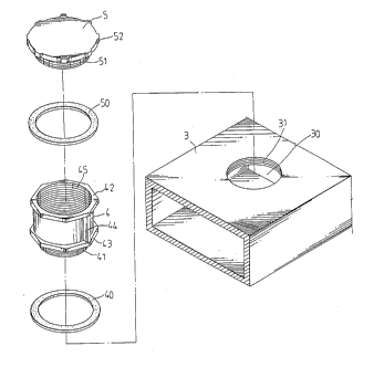
Fig. 3 illustrates a floor wiring box constructed
according to the present invention;
Fig. 4 is a perspective dismantled view of the present
invention;
Fig. 5 is a sectional assembly view of the present
invention; and
Fig. 6 illustrates an alternate form of the present
invention.

2032659
Fig. 1 illustrates a wiring conduit according to the prior
art, which has a stub tube for mounting a plug through screw joint.
Because the stub tube projects from the top edge of the wiring conduit,
it may be easily damaged or deformed during ~lal~ a~ion. Further,
after a plug is fastened in the stub tube through screw joint, water or
moisture may permeate through the gap ~ ,iW~, causing
electrical leakage problems.
Fig. 2 illustrates another type of wiring conduit
according to the prior art, which has a round hole with two opposite
notches made thereon at the top for mounting a plug. Because the
round hole is formed by a punching process, high precision is difficult
to achieve. Therefore, the gap cannot be completely eliminated after
a plug is fastened in the round hole. As a result, water or moisture
may permeate into the wiring conduit to cause electrical leakage
lS problems.
Referring to Figs. 3 and 4, a wiring conduit 3 is
fastened in a wiring box 6 and embedded in the concrete floor of a
building for distribution of electric wire. A bolt hole 30 which has an
inner thread 31 is made on the wiring conduit 3 at the top for
mounting a plug 4 which is covered with a cap 5 and disposed out of
the concrete floor.
B

2032659
By removing the cap 5 from the plug 4, electric wire from the
wiring box 6 can be connected to a Plug socket for supplymg
electrlcity to any electric appliances connected thereto.
The plug 4 co~prises a first octagonal flange 42 at the top,
a second octagonal flange 43 at the middle, two unitary ribs
44 longitudinally disposed betueen said first and sscond
octagonal flanges 42 and 43 at two opposite locations, a
connecting end 41 at the bottoD which has an outer thread for
connection uith the inner thread 31 of the bolt hole 30, and
an inner thread 45 for mounting the cap 5 through screw
joint. Through the ribs 44, the plug 4 can be conveniently
rotated to fasten in the bolt hole 30 of the wire conduit 3.
The cap 5 has a connecting end 51 which has outer thread 51
for connection with the inner thread 45 of the plug 4.
There are eight projecting edges 52 equidistantly made around
the periphery of the cap and respectively disposed in a
horizontal position. Through the projecting edges 52, the
cap 5 can be conveniently rotated to fasten in or rsmove from
the plug 4. Before fastening in the bolt hole 30 of the
wire conduit 3, a gasket ring 40 is mounted on the connecting
end 41 of the plug. In the saDe Danner, before fastening in
the inner thread 45 of the plug 4, a gasket ring 50 is

~32659

Dounted on the connecting end 51 of the cap 5. Therefore,
after the plug 4 and the cap 5 are respectively fastened in
the bolt hole 30 of the wire conduit 3 or the inner thread
45 of the plug 4, ~ater or Doisture is Prohibited from
entering the wire conduit 3 through the bolt hole 30.
Referring to Fig. 6, a screw pipe coupling 7 may
be used to connect two plugs 4 together, so as to extend the
total height fro~ the wiring conduit 3. As illustrated, a
screw pipe coupling 7 has a top flange 71, which has eight
projecting edges equidistantly made around the peripherY
thereof and through which a screw pipe coupling 7 can be
conveniently rotated for fastening, an outer thread for
connection with the inner thread 45 of the plug 4 or the
inner thread 31 of the bolt hole 30, and an inner thread 72
for fastening the connecting end 41 of the plug 4. Before
mounting, a gasket ring 70 is Dounted on the screw pipe
coupling 7. Therefore, the gap between the plug 4 and the
screw pipe coupling 7 is sealed. By Deans of aforesaid
arrangeDent, a plurality of plugs 4 can be connected together
and fastened in the wire conduit 3 to seal the bolt hole 30.

Representative Drawing
A single figure which represents the drawing illustrating the invention.
Administrative Status

For a clearer understanding of the status of the application/patent presented on this page, the site Disclaimer , as well as the definitions for Patent , Administrative Status , Maintenance Fee  and Payment History  should be consulted.

Administrative Status

Title Date
Forecasted Issue Date 1995-02-14
(22) Filed 1990-12-19
(41) Open to Public Inspection 1992-06-20
Examination Requested 1993-12-03
(45) Issued 1995-02-14
Deemed Expired 1996-06-19

Abandonment History

There is no abandonment history.

Payment History

Fee Type Anniversary Year Due Date Amount Paid Paid Date
Application Fee $0.00 1990-12-19
Maintenance Fee - Application - New Act 2 1992-12-21 $50.00 1992-12-03
Maintenance Fee - Application - New Act 3 1993-12-20 $50.00 1993-10-21
Maintenance Fee - Application - New Act 4 1994-12-19 $50.00 1994-12-01
Owners on Record

Note: Records showing the ownership history in alphabetical order.

Current Owners on Record
YANG, CHIN-HUI
Past Owners on Record
None
Past Owners that do not appear in the "Owners on Record" listing will appear in other documentation within the application.
Documents

To view selected files, please enter reCAPTCHA code :


To view images, click a link in the Document Description column. To download the documents, select one or more checkboxes in the first column and then click the "Download Selected in PDF format (Zip Archive)" or the "Download Selected as Single PDF" button.

List of published and non-published patent-specific documents on the CPD .

If you have any difficulty accessing content, you can call the Client Service Centre at 1-866-997-1936 or send them an e-mail at CIPO Client Service Centre.


Document
Description 
Date
(yyyy-mm-dd) 
Number of pages   Size of Image (KB) 
Cover Page 1995-02-14 1 11
Abstract 1995-02-14 1 14
Description 1995-02-14 6 101
Abstract 1995-02-14 1 14
Drawings 1995-02-14 3 62
Claims 1995-02-14 2 29
Representative Drawing 1999-07-07 1 15
Office Letter 1994-02-07 1 64
PCT Correspondence 1994-12-02 1 54
Prosecution Correspondence 1994-06-27 2 54
Examiner Requisition 1994-04-11 2 52
Prosecution Correspondence 1993-12-03 2 64
Fees 1994-12-01 1 39
Fees 1993-10-21 1 39
Fees 1992-12-03 2 66