Language selection

Search

Patent 2032915 Summary

Third-party information liability

Some of the information on this Web page has been provided by external sources. The Government of Canada is not responsible for the accuracy, reliability or currency of the information supplied by external sources. Users wishing to rely upon this information should consult directly with the source of the information. Content provided by external sources is not subject to official languages, privacy and accessibility requirements.

Claims and Abstract availability

Any discrepancies in the text and image of the Claims and Abstract are due to differing posting times. Text of the Claims and Abstract are posted:

  • At the time the application is open to public inspection;
  • At the time of issue of the patent (grant).
(12) Patent Application: (11) CA 2032915
(54) English Title: BEAM COMBINING/SPLITTER CUBE PRISM FOR COLOR POLARIZATION
(54) French Title: PRISME CUBIQUE DE COMBINAISON ET DE DIVISION DE FAISCEAUX UTILISANT LA COULEUR ET LA POLARISATION
Status: Dead
Bibliographic Data
(52) Canadian Patent Classification (CPC):
  • 88/117
  • 88/98
(51) International Patent Classification (IPC):
  • G02B 27/10 (2006.01)
  • G02B 27/28 (2006.01)
(72) Inventors :
  • GOLD, RONALD S. (United States of America)
  • JACHIMOWICZ, KAREN E. (United States of America)
(73) Owners :
  • HONEYWELL INC. (United States of America)
(71) Applicants :
(74) Agent: SMART & BIGGAR
(74) Associate agent:
(45) Issued:
(22) Filed Date: 1990-12-21
(41) Open to Public Inspection: 1991-06-28
Examination requested: 1997-12-18
Availability of licence: N/A
(25) Language of filing: English

Patent Cooperation Treaty (PCT): No

(30) Application Priority Data:
Application No. Country/Territory Date
07/457,665 United States of America 1989-12-27

Abstracts

English Abstract


ABSTRACT OF THE DISCLOSURE
A cube bi-prism for beam combining and/or
splitting through color and polarization multiplexing.


Claims

Note: Claims are shown in the official language in which they were submitted.


- 7 -
64159-1178

THE EMBODIMENTS OF THE INVENTION IN WHICH AN EXCLUSIVE
PROPERTY OR PRIVILEGE IS CLAIMED ARE DEFINED AS FOLLOWS:

1. A color polarization cube prism for combining/splitting
light, comprising:
a cube, composed of an essentially transparent
material, having first, second, third, fourth, fifth and sixth
sides, and having first and second halves of said cube juxtaposed
at a plane, wherein the first and second halves have boundaries
on the third and fourth sides;
a first optical coating, situated between the first and
second halves;
a first wave retarder proximate to the third side;
a second wave retarder proximate to said first wave
retarder; and
a second optical coating situated between said first
and second wave retarders; and
wherein:
said first optical coating transmits light having a
first polarization and reflects light having a second
polarization;
said second optical coating is a dichroic filter;
said first wave retarder is a quarter-wave plate;
said second wave retarder is a three-quarter-wave
plate;
a first light, having a first polarization, enters the
first side of said cube, passes through said first optical
coating, and exits said cube at the second side;


- 8 -
64159-1178

a second light, having a second polarization, passes
through said second wave retarder, said second optical coating
and said first wave retarder, enters the fifth side of said
cube, impinges the first optical coating and is reflected out of
said cube through the second side; and
a third light, having a first polarization, enters the
sixth side of said cube, passes through the first optical
coating, exits said cube at the fifth side, passes through said
first retarder, impinges said second optical coating and said
third light is reflected by said second optical coating back
through said first retarder and said third light, having its
polarization changed to the second polarization, passes through
the fifth side into said cube, impinges said first optical
coating and said third light is reflected out of said cube
through the second side.

2. A color polarization cube prism for combining/splitting
light, comprising:
a cube, composed of an essentially transparent
material, having first, second, third, fourth, fifth and sixth
sides, and having first and second halves of said cube juxtaposed
at a plane, wherein the first and second halves have boundaries
on the third and fourth sides;
a first film coating between the first and second
halves;
a first wave retarder proximate to the first side;
a second wave retarder proximate to said first wave
retarder; and


- 9 -
64159-1178

a second film coating situated between said first and
second wave retarders; and
wherein:
said first film coating transmits light having a first
polarization and reflects light having a second polarization;
said second film coating is a dichroic filter;
said first and second wave retarders are quarter-wave
plates;
a first light, having a second polarization, enters
said cube through the fifth side, impinges said first film
coating and said first light is reflected by said first film
coating, and said first light exits said cube through the second
side;
a second light, having a second polarization, enters
said cube through the sixth side, impinges said first film
coating, said second light is reflected by said first film
coating, said second light exits said cube through the first side,
said second light passes through said first wave retarder,
impinges said second film coating, said second light is reflected
by said second film coating through said first wave retarder and
said second light, having its polarization changed to the first
polarization, passes through the first side into said cube,
through said first film coating and out of said cube through the
second side; and
a third light, having the second polarization, passes
through second wave retarder, second film coating, first wave
retarder and said third light, having its polarization changed to


- 10 -
64159-1178

the first polarization, enters through the first side into said
cube, passes through said first film coating and exits said cube
through the second side.


3. Apparatus of claim 1 wherein:
said first light is green;
said second light is blue; and
said third light is red.


4. Apparatus of claim 1 wherein:
said first light is blue;
said second light is red; and
said third light is green.


5. Apparatus of claim 2 further comprising:
a first compensator block proximate to the fifth side
of said cube such that said first light passes through said
first compensator block before entering said cube through the
fifth side; and
a second compensator block proximate to said second
wave retarder such that said third light passes through said
second compensator block before entering said second wave
retarder.


6. Apparatus of claim 5 wherein:
said first light is a first color;
said second light is a second color; and
said third light is a third color.


- 11 -
64159-1178

7. Apparatus of claim 6 wherein:
said first color is green;
said second color is blue; and
said third color is red.


8. Apparatus of claim 6 wherein:
said first color is red;
said second color is green; and
said third color is blue.


9. Apparatus of claim 2 further comprising an optical
compensating means proximate to said fifth side of said cube.
Description

Note: Descriptions are shown in the official language in which they were submitted.


2~2~J


a4213441-US
BEAM COMBINING/SPLITTER CUBE
PRISM FOR COLOR POLARIZATION

Field of the Invention
The present invention pertains to light beam
control, particularly to b~am combining and splitting
dependent on beam color and polarization. More
particularly, the invention pertains to light beam
combining and splitting.
~; 10
Backqround of the Invention
Various approaches have been used for beam
combining and splitting. A most common one has been a
quad-combining prism. The "quad" prism (i.e., a four
piece prism such four solid pieces, fluid-filled
pieces or other sorts of media) has been difficult to
fabricate and align for precise operation. Such prism
i5 disclosed in U.S. patent application of serial
number 07/~37,488.
; Summary of the Invention
The present invention is a bi-prism for
combining and/or splitting light beams. The bi-prism


6415g-1178

is easier to fabricate and align than the quad-prism since the
latter is a four piece device and the former is a two piece
prism. The bi-prism functions with similar results but in a
different way than the quad-prism. The invention is useful in
many applications where polarized color combining and splitting
is advantageous.
Brief Description of the Drawings
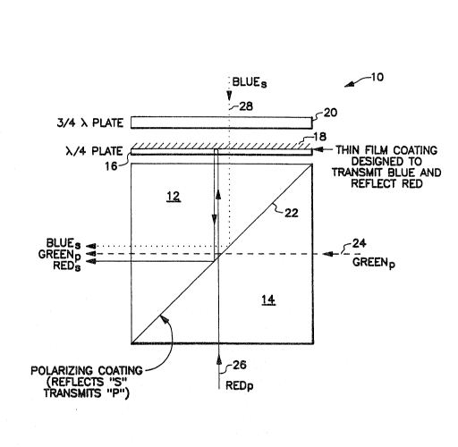
Figure 1 illustrates a cube bi-prism light beam
combiner/splitter.
Figure 2 is a perspective view of the cube bi-prism.
Figure 3 illustrates another embodiment of the
invention.
Description of the _referred Embodiment
Figure l is an illustration of present invention lO.
Invention lO comprises two prisms 12 and 14, respectively,
having polarized coating 22 at their junction, quarter-wave
plate 16 having a thin-film dichroic coating 18, and three-
quarter-wave plate 20. Figure 2 is a perspective view of prisms
; 12 and 14, showing six labelled sides 1, 2, 3, 4, 5 and 6 of
bi-prism 11. Prisms 12 and 14 share sides 3 and 4.
In a typical application of device lO, green light 24
having "P" polarization is transmitted

~ ~ I s ~ V~ ~ ~
- 3 -


through side 1 into prism 14, through polarizing
coating 22 and into prism 12. Light 24 exits side 2.
Light having "P" polarization has its E field vector
parallel to the plane of incidence. Light having "S"
polarization has its E field vector perpendicular to
the plane of incidence. Polarizing coating 22
transmits light having "P" polarization and reflects
light having "S" polarization.
Red light 26 having "P" polarization enters
prism 14 through side 6, approximately perpendicular
to the direction of green light 24. Red light 26 is
transmitted through prism 14, coating 22 and prism
12. Red light 26 exits prism 12 from side 5 and
proceeds through c~arter-wave plate or retarder 16
until it is reflected by coating 18 on plate 16.
Coating 18 is designed to reflect red light and
transmit blue light. The fast axis of quarter-wave
plate 16 is oriented 45 degxees to the axis of
incoming linearly polarized light, such as "P"
polarized red light 26, causing linearly polarized
ligh~ 26 to become circularly polarized. Upon
reflectio~ of circularly polarized light from coating
or filter 18, the orientation of circular polarization
of light 26 is reversecl. Passage of red light 26 from
filter 18 back through quarter-wa~e plate 16 changes
the circular polarization of light 26 back to linear


~ ~ ~ rr;~
-- 4 --


polarization, but with its orientation orthogonal to
the original input "P" polarization, thereby resulting
in "S" polarized red light 26 entering prism 12
through side 5. Light 26 of "S" polarization impinges
coating 22 and is reflected by coating 22 out of prism
12 through side 2.
Blue light 28 having the "S" polarization
travels through three-quarter-wave retarder 20,
optical means or film coating 18 and quarter-wave
retarder 16. A full wave of retardation is introduced
into blue light 28, by retarders 20 and 16, which has
no resultant effect on the "S" polarization of light
:~ 28. If blue light 28 were "P" polarized, then
thr~-quarter-wave retarder 20 could be replaced with
a quarter-wave retarder for a total of half-wave
retardation, thereby rotating the polarization vector
(i.e., E field vector) 90 degrees to the desired "S"
polarization for light 28. Blue light 28 enters prism
12 through side 5 and impinges coating 22. Coating 22
reflects "S" polarized light 28 out of prism 12
through side 2. Thus, green light 24, red light 26
and blue light 28 exit prism 12 in the same direction
of propagation. Light 24, 25 and 28 may be of other
colors, and films 18 and 22 may have various
properties, depending upon the application of device
10 .


-- 5 --


Figure 3, in conjunction with figure 2,
reveals embodiment 30 of the present invention having
optical compensation for at least two of the three
light beams. Optical compensation provides optical
path length adjustment. Such compensation may be in
the form of lenses, transparent blocks or other
means. Green light 26 having the "S" linear
polarization is transmitted through compensation block
38 and into prism 12 through side 5. Light 26
impinges coating 22 which reflects "S" polarized light
` and transmits "P" polarized light. Thus, light 26 is
reflected by coatinq 22 and then light 26 exits prism
12 through side 2. Red light 24 is transmitted
through compensation block 40, guarter-wave plate 36,
thin film coating 34 which is a long wave pass filter
(i.e., it reflects blue and transmits red light), and
~i
quarter wave plate 32. Quarter wave platPs 36 and 32
cause a total of one-half wave retardation of light
24~ there~y rotating the polarization vector 90
degrees to the "P" polarization position (i.e.,
quarter-wave (half-wave total) plates each has an axis
at 45 degrees to the E field vector of polarized light
to rotate the vector for a total of 90 degrees). "P"
polarized red light 24 exits plate 32, enters prism 14
through side l, passes through coating 22 into prism
12 and exits prism 12 through side 2. "S" polarized


3,~ J


blue light 28 enters prism 14 through side 6 and is
reflected by coating 22 out of prism 14 through side 1
and light 28 goes through quarter-wave plate 32 to
coating 34. Light 28 is then reflected by coating 34
back through quarter-wave plate 32. Since light 28
goes through plate 32 twice, there is a total of
one-half wave retardation of light 28, thereby
rotating the polarization vector 90 degrees to a "P"
polarization position. Light 28 returning from plate
32 reenters prism 14 through side 1 and passes through
coating 22 into prism 12. Light 28 exits prism 12
through side 2 in the same direction of propagation as
light 24 and 26.
Light 24, 26 and 28 may be any combination of
: 15 colors. Films or coatings 22 and 34 may have various
transmissive and reflective properties as needed to
accommodate the designated colors of light 24, 26 and
28, for achieving desired properties of device 30.


:
,, :

Representative Drawing
A single figure which represents the drawing illustrating the invention.
Administrative Status

For a clearer understanding of the status of the application/patent presented on this page, the site Disclaimer , as well as the definitions for Patent , Administrative Status , Maintenance Fee  and Payment History  should be consulted.

Administrative Status

Title Date
Forecasted Issue Date Unavailable
(22) Filed 1990-12-21
(41) Open to Public Inspection 1991-06-28
Examination Requested 1997-12-18
Dead Application 2000-12-21

Abandonment History

Abandonment Date Reason Reinstatement Date
1999-12-21 FAILURE TO PAY APPLICATION MAINTENANCE FEE

Payment History

Fee Type Anniversary Year Due Date Amount Paid Paid Date
Application Fee $0.00 1990-12-21
Registration of a document - section 124 $0.00 1991-05-31
Maintenance Fee - Application - New Act 2 1992-12-21 $100.00 1992-11-23
Maintenance Fee - Application - New Act 3 1993-12-21 $100.00 1993-11-19
Maintenance Fee - Application - New Act 4 1994-12-21 $100.00 1994-11-24
Maintenance Fee - Application - New Act 5 1995-12-21 $150.00 1995-11-20
Maintenance Fee - Application - New Act 6 1996-12-23 $150.00 1996-12-09
Maintenance Fee - Application - New Act 7 1997-12-22 $150.00 1997-12-09
Request for Examination $400.00 1997-12-18
Maintenance Fee - Application - New Act 8 1998-12-21 $150.00 1998-12-08
Owners on Record

Note: Records showing the ownership history in alphabetical order.

Current Owners on Record
HONEYWELL INC.
Past Owners on Record
GOLD, RONALD S.
JACHIMOWICZ, KAREN E.
Past Owners that do not appear in the "Owners on Record" listing will appear in other documentation within the application.
Documents

To view selected files, please enter reCAPTCHA code :


To view images, click a link in the Document Description column. To download the documents, select one or more checkboxes in the first column and then click the "Download Selected in PDF format (Zip Archive)" or the "Download Selected as Single PDF" button.

List of published and non-published patent-specific documents on the CPD .

If you have any difficulty accessing content, you can call the Client Service Centre at 1-866-997-1936 or send them an e-mail at CIPO Client Service Centre.


Document
Description 
Date
(yyyy-mm-dd) 
Number of pages   Size of Image (KB) 
Claims 1994-03-30 5 147
Abstract 1994-03-30 1 6
Drawings 1994-03-30 2 50
Description 1994-03-30 6 189
Cover Page 1994-03-30 1 17
Representative Drawing 1999-07-19 1 16
Assignment 1990-12-21 8 306
Prosecution-Amendment 1997-12-18 1 51
Fees 1996-12-09 1 84
Fees 1995-11-20 1 85
Fees 1994-11-24 2 139
Fees 1993-11-19 1 58
Fees 1992-11-23 2 102