Note: Descriptions are shown in the official language in which they were submitted.
Method and Apparatus for Stretching Dough 0334 06
Background of the Invention
Field of Invention
This invention relates to a method and apparatus for
stretching plastic material, and, more particularly, to a
method and apparatus for stretching dough for bread or confectionery.
Description of Prior Art
The prior art related to the stretching of dough of
this invention is disclosed in U.S. Patent Nos. 4,692,110 and
4,631,021, both of which`issued to the assignee of this applicant.
U.S. Patent No. 4,692,110 discloses a dough-stretching
apparatus whose object is to stretch a mass of supplied dough
into a sheet of dough having a predetermined thickness. However,
this apparatus is neither capable of making the width of the
stretched sheet of dough uniform, nor of producing the stretched
sheet of dough at a constant production speed.
U.S. Patent No. 4,631,021 discloses an apparatus for
producing a sheet of dough having predetermined dimensions and
delivering it at a predetermined delivery rate to produce a sheet
of dough having a uniform shape. However, the proposed means
is based on the measurement of the weight of a mass of dough supplied
in an indefinite shape before the stretching step.
r
SUMMARY OF THE INV ~:N~1~ION
This invention provides an automatic dough-stretching
apparatus which produces a continuous sheet of dough used for
the production of bread and confectionery and in which the manufacturing
parameters, including the production speed, width, and thickness
of the sheet of dough, are previously stored in a computer memory,
so that a mass of dough supplied with a non-uniform width or thickness
- 2 - 2033406
can be automatically stretched into a sheet of dough that satisfies
the conditions stored in the computer memory.
The dough-stretching apparatus of the present invention
includes a compressing device located above a dough-supplying
conveyor so as to make uniform the height of a mass of dough
supplied in an indefinite shape. When the height of the mass
of the supplied dough is made uniform, the only variable in
the dimensions of the stretched sheet of dough will be its
width. Therefore, by merely continuously measuring the width
of the sheet of dough passing through a measuring position,
the volume of portions of the dough sheet at that position
can be continuously or sequentially recorded in the computer
memory. Based on the volume data stored in the memory, the
speed of the dough-supplying conveyor is suitably and continuously
changed so that the amount of the sheet of dough transferred
per unit time from the dough-supplying conveyor onto a delivery
conveyor is made uniform.
Therefore, it is an object of the present invention
to provide a dough-stretching method for continuously compressing
a supplied mass of a non-uniform volume of dough into a dough~
sheet of a uniform volume, comprising the steps of:
conveying the supplied mass of the non-uniform
volume of dough on a supplying conveyor to a delivery conveyor
located downstream of the supplying conveyor,
compressing the mass of dough on the supplying
conveyor into a dough sheet having a uniform thickness,
detecting the dough width at the point where the
dough is compressed,
setting the speed of the supplying conveyor relative
20~3406
to the speed of the delivery conveyor, based on the detected
value of the dough width, and
further stretching the dough on the delivery conveyor.
Another object of the present invention is to provide
a dough-stretching apparatus comprising:
a dough-supplying conveyor for conveying a continuous
sheet of dough and a constant-speed delivery conveyor positioned
in series with and downstream of the supplying conveyor,
a roller for applying pressure to the dough, disposed
at the downstream end of the supplying conveyor,
a dough-width measuring device located near the
pressure-applying roller, and
the dough-width measuring device being arranged
so as to measure the width of the dough when it is compressed
by the pressure-applying roller and to change the speed of
the supplying conveyor in a relation inversely proportional
to the value of the dough width before it is supplied onto
the delivery conveyor,
thereby to produce at a constant speed a dough
sheet of a uniform width and thickness.
A further object of the present invention is to
provide a dough-stretching apparatus comprising:
a dough-supplying conveyor for conveying a continuous
sheet of dough and a constant-speed delivery conveyor positioned
in series with and downstream of the supplying conveyor,
-~ Z0~3406
one or a plurality of rollers located above and
adjacent the area between the downstream end of the supplying
conveyor and the upstream end of the delivery conveyor, the
roller or rollers reciprocating over a predetermined range
while rolling along the moving path of the two conveyors,
and
a dough-width measuring device located adjacent
the downstream end of the supplying conveyor,
the speed of the supplying conveyor being changed
based on the measured value of the measuring device, while
the speed of the delivery conveyor is kept constant.
A further object of the present invention is to
provide a dough-stretching apparatus comprising:
a dough-sheet supplying conveyor with a variable
speed to supply a continuous sheet of dough and a delivery
conveyor with a constant speed positioned in series with
and downstream of the supplying conveyor,
a plurality of freely rotatable rollers spaced
apart from each other and from the conveyors and above the
area between the downstream end of the supplying conveyor
and the upstream end of the delivery conveyor, the rollers -
orbiting above said area, the dough being supplied into the
space between the rollers and the upper surface of the supplying
conveyor and causing the rollers to rotate by friction with
the dough sheet, and
a dough-width measuring device located at the downstream
end of the supplying conveyor to measure the dough width
2()~3406
and to set the speed of the supplying conveyor in a relation
inversely proportional to the measured value.
Brief Description of the Drawings
Fig. 1 is a schematic side elevational view of
a first embodiment of the apparatus of the present invention;
Fig. 2 is a top plan view of the embodiment shown
in Fig. l;
Fig. 3 shows a schematic cross section of the apparatus
taken along the line 3-3 in Fig. 1;
Fig. 4 is a schematic side elevational view of
a second embodiment of the apparatus of the present invention;
Fig. 5 is a schematic side elevational view of
a third embodiment of the apparatus of the present invention;
Fig. 6 is a schematic top plan view of those apparatuses
shown in Figs. 4 and 5;
Fig. 7 is a schematic side elevational view of
a fourth embodiment of the apparatus of the present invention;
Fig. 8 is a schematic side elevational view of
a fifth embodiment of the apparatus of the present invention;
and
Fig. 9 schematically illustrates a rotation input
mechanism that actuates the reciprocating rollers shown in
Fig. 7.
Preferred Embodiments of the Invention
(Working Examples)
Preferred embodiments of the present invention will
now be described by reference to the attached drawings.
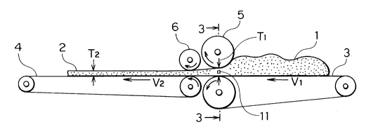
A mass of dough 1 with an indefinite shape is placed
on a dough-supplying conveyor 3. Downstream of the supplying
conveyor 3 is positioned a delivery conveyor 4. A dough-
~ 2()33406
compressing means in the form of a dough feed roller 5 ispositioned at the downstream end of and above the supplying
conveyor 3, spaced apart from the conveying path of the supplying
conveyor 3 by a predetermined distance, Tl.
In Fig. 1, two distance sensors 11 are disposed,
one on each side of the conveying path of the conveyor 3 and
near the roller 5 (width-measuring) position. The distance
sensors 11 sense the distance between the respective sides
of the mass of dough 1, and send signals representing the
distance to the computer 12 (Fig. 7) which computes the width
Wl (Fig. 2) of the mass of dough 1.
The dough-feed roller 5 compresses and makes the
height of the dough 1 uniform. The sectional area S (Fig.
3) of the mass of dough 1 at the width-measuring position
is given by the formula S = Wl X Tl, wherein Tl is the height
of the dough under the roller 5.
The computer 12 thus computes the sectional area
S of the mass of the dough 1 at the width-measuring position
according to the equation Wl X Tl = S. Then, on the basis
of the computed value of the sectional area S, the computer
12 computes the desired speed Vl for the dough-supplying conveyor
3 and sends signals to the servomotor 13 (Fig. 7) to control
its rotation. The servomotor 13 thus adjusts the speed V
of the conveyor 3.
A compressing means such as, for example, the shaping
roller 6, is located above the delivery conveyor 4. The
roller 6 reduces the thickness of the dough to T2. The data
representing the desired width W2 (Fig. 2) and thickness
T2 of the dough sheet 2 to be produced are stored, together
with the data representing the desired production speed V2,
in the memory of the computer 12. The dough-stretching operation
~ 20~34(~6
is carried out while the speed of the delivery conveyor 4
is maintained at the value V2. The computer 12 continuously
controls the speed V1 of the dough-supplying conveyor 3 so
as to satisfy the following relation:
T2 X W2 X V2 = Tl X Wl X Vl
Due to the speed difference between the dough-supplying conveyor
3 and the delivery conveyor 4, a dough sheet 2 having the
desired thickness T2 and the desired width W2 can be produced.
The apparatus of the second embodiment of the present
invention, shown in Fig. 4, features a single roller. That
is, the reciprocating roller 7 acts as both the compressing
means to make the height of-the mass of dough l uniform so
that it has the value Tl and the means for determining the
thickness T2 of the stretched sheet of dough 2 of the first
embodiment. The reciprocating roller 7 repeats its reciprocating
movement while rolling over an illustrated range ~. The
range ~ includes a range A between the upstream operating
limit of the roller 7 and the downstream end 3' of the dough-
supplying conveyor 3, and a range B between the downstream
operating limit of the roller 7 and the upstream end 4' of
the delivery conveyor 4. Thus the roller flattens the upper
surface of the mass of dough l having the indefinite shape,
determines the dough thickness Tl at a width-measuring position
on the dough-supplying conveyor 3, and determines the dough
thickness T2 on the delivery conveyor 4.
In Fig. 4, the position of the downstream end 3'
of the dough-supplying conveyor 3 is selected to be higher
than the upstream end 3" of the conveyor 3. The purpose of
this structure is to greatly enhance the effect of compressing
and shaping the dough by the operation of the roller 7 that
reciprocates while it rolls. Namely, since the dough-supplying
conveyor is inclined relative to the delivery conveyor, the
mass of dough can smoothly enter the space between the roller
7 and the conveyor 3, and the dough can be easily and effectively
. 66757-67
2()~3406
-- 8 --
flattened.
The distance sensors 11 sense the width W2 of the
mass of dough 1.
The sectional area S of the mass of dough 1 at the
width-measuring position can be expressed as S = Tl X Wl. Further,
the controlled speed Vl of the dough-supplying conveyor 3 relative
to the constant speed V2 of the delivery conveyor 4 is calculated
according to the following equation:
T2 X W2 X V2 = Tl X Wl X Vl
where Tl is a constant, Wl is a variable, and Vl is a variable
determined by the value of (Tl X Wl).
Based on the above equation, the computer 12 controls
the rotating speed of the servomotor 13 (Fig. 7) to attain
the desired control.
A third embodiment of the present invention is shown
in Figs. 5 and 6. The apparatus shown in Figs. 5 and 6 is
a modification of that shown in Fig. 4 in that the dough-supplying
conveyor 3 is disposed in the horizontal direction at a level
lower than the level of the delivery conveyor 4.
In the fourth embodiment of the present invention,
shown in Fig. 7, the apparatus`has two linked reciprocating
rollers 8 and 9 that are arranged so that the reciprocating
roller 8 substantially reciprocates over a range Ql above the
dough-supplying conveyor 3 and a part of the delivery conveyor
4, while the reciprocating roller reciprocates over a range Q
2 above the delivery conveyor 4. By this arrangement, the
reciprocating roller 9 rotates so that its peripheral speed
is equivalent to the speed V2 of the delivery conveyor, while
the roller 8 rotates so that its peripheral speed is equivalent
to the speed Vl of the dough-supplying conveyor 3.
Fig. 9 shows a rotation input mechanism for the reciprocating
rollers 8 and 9. A chain 14 is arranged to be driven in the
same direction and at the same speed as is the delivery conveyor
2~33406
4. A sprocket 9' meshing with this chain 14 is mounted on
one end of the shaft of the roller 9.
A crank 16 and a rod 15 act to cause a reciprocating
movement of the sprocket 9' engaging the chain 14, so that
the roller 9 reciprocates over the range Q2 while rolling.
Another sprocket 8' is mounted on one end of the shaft of the
reciprocating roller 8 and also engages the chain 14, so that
the roller 8 similarly reciprocates over the range Q1 while
rolling. In this case, the diameter of the sprocket 8' is
selected to be larger than that of the sprocket 9', so that
the peripheral speed of the sprocket 8' is lower than that
of the sprocket 9'. Therefore, when the rollers 8 and 9 have
the same diameter, the roller 8 rolls so that its peripheral
speed becomes the same as the speed of the mass of dough 1
being conveyed by the dough-supplying conveyor 3, whose speed
V1 is lower than the speed V2 of the delivery conveyor 4.
In the apparatus according to the fifth embodiment
shown in Fig. 8, the number 10 designates the group of many
rollers revolving along a predetermined orbit while rotating.
The path of orbital motion is rectilinear in its lower part.
The roller group 10 stretches the mass of dough 1 in the range
covering the downstream end of the dough-supplying conveyor
3 and the upstream end of the delivery conveyor 4. Thus, a
stretching effect similar to that already described is exhibited
so as to attain the object of the present invention.
As was the case with the second embodiment, the dough
is effectively compressed and shaped in the fourth and the
fifth embodiments, since the dough-supplying conveyor 3 is
inclined upwardly toward the delivery conveyor 4.
It will be understood from the foregoing description
of the present invention that a mass of dough supplied in an
indefinite shape can be stretched into a sheet of dough having
a constant volume by making uniform the height of the mass
- lo - 20~3406
of dough on a dough-supplying conveyor, by detecting a change
in the dough width resulting from making the height of the
dough uniform, by computing a corresponding speed difference
between the dough-supplying conveyor and a delivery conveyor
disposed on the downstream side of the supply conveyor and
driven at a constant speed, and by driving the dough-supplying
roller at the speed corresponding to the computed speed difference.
Thus, the present invention solves the prior art
defects and can produce a sheet of dough having a high quality,
and can do so with a high accuracy.