Note: Descriptions are shown in the official language in which they were submitted.
2033679
ME~HOD AN~ SYSTEM FOR OPTIMIZING AUDIO
IMAGING IN AN AUTOMOTIVE LISTENING ENVIRONMENT
Field of the Invention
S T~is invention relates to the ~ield of audio
signal processing and more specifically to a method and
system for optimizing the audio image perceived by a
driver and passengers in an automotive listening
environment.
~ackaround of the Invention
. . ,
Audio systems have become increasingly popular
in recent years, and much development effort has been
directed toward improving the guality and integrity of
their audio imaging. One important aspect of audio
imaging is the creation of a sound field in which a
listener perceives depth and directional qualities in the
sound field created by a plurality of sources.
One example o~ a multi-channel audio system
which provides an enhanced sound field is described in
United States Patent Nos. 3,632,886, 3,746,792, and
3,959,590, all invented by Scheiber~ In Scheiber's
system, as many as ~our audio channels may be encoded to
two channels for recording or transmission and decoded at
playback to produce multiple channels ~typically four) of
audio information. In this type of system, speakers or
transducers are placed peripherally around a listener to
produce a sound fiQld in which sound may be perceived as
originating from substantially any direction.
Another example of a multi-channel audio system
which provides an enhanced sound field is the well known
~surround sound~ audio system designed by Dolby
La~oratories. In this system, multiple channels of audio
information are also encoded to two channels for recording
and decoded at playback to produce a multi-dimensional
sound f ield. In this system, the primary sound sources
are located in front of a listener and secondary sound
.
. ...~., ~, .. ~ ....
2033679
sources are disposed peripherally around a listener to
create the desired directional effects. This system is
particularly popular for use with the audio portions of
motion pictures.
Still another multi-channel sound system i5
described in United States Patent No. 4,478,167, invented
by Borkin. Borkin teaches a three channel sound system in
which speakers are located in a triangular pattern around
a listener. In Borkin's system, a center channel signal
is derived by summing a portion of left side channel
signal and a portion of the right side channel signal. In
addition, a portion of the right side signal is cancelled
from the left side channel and a portion of the left side
signal is cancelled from the right side channel.
lS According to Borkin, the proportions of the amount of side
channel cancellation range from approximately 2/3-3/4 to
achieve the desired results. In Borkin's system, the gain
of each of the audio channels is identical and fixed, thus
requiring transducers of equal size wherein the placement
of the transducers relative to the listener is critical.
While each of the above systems provides an
enhanced sound field in a spacious environment such as a
home living room or movie theater, they are not
particularly useful for use in an automotive environment.
As exemplified by the systems noted above, much
development effort has been directed toward bolstering the
directional information present in a sound field and the
above systems function quite well in installations where
sound sources and listeners can be positioned in optimal
locations. However, in an automotive environment, the
~, .
location of listeners relative to sound sources cannot be
readily adjusted. For example, sound sources in
automobiles are typically placed in doors, side panels or
rear decks, and once installed, cannot be moved. The
position of the listeners, in this case a driver and one
or more passengers, is necessarily fixed by the location
of seats within the automobile. If the sound system is
.
.; : : -:- . -- .
-- . .:
:-
: :~
:, .
2033679
adjusted to produce a balanced sound field proximateeither the driver or passengers, the sound field will be
unbalanced near the other occupants of the automobile. No
system is known which allows a sound field to be optimized
for one occupant of an automobile while also providing an
optimally balanced sound field for the other occupants of
an automobile. Furthermore, no system is known which
generates a balanced sound field in a center channel sound
system wherein the components used in the center channel
may be smaller than the side channel components and
further wherein the placement of the center channel
transducer is not critical.
SummarY and Ob;ects of the Invention
Briefly described, the present invention
contemplates an audio system for optimizing a sound field
for a plurality of listeners positioned in diverse
locations in a listening environment. In operation, first
and second audio signals, typically comprising left and
right audio signals, are input from an audio source. The
first and second audio channels are summed to generate a
composite audio signal. A portion of the composite audio
signal is cancelled from the left and right audio signals
to generate left and right output signals, respectively,
wherein the composite audio signal comprises a center
channel output signal. In one aspect of the present
invention, the gain of the side channel cancellation
signal is limited to .S to preserve substantially all of
the perceptible directional information in the left and
right side channels. In yet another aspect of the present
invention, the center channel output signal is high-pass
filtered to remove low frequency information from the
center channel thus allowing a relatively smaller
transducer to be used in the center channel. In yet
another aspect of the present invention, the overall gain
of the center channel is adjustable to allow the
sensitivity of the center channel to be adjusted to match
: . , : :: , . . :
-
,
. :
2033679
the center channel components to the other components used
in the system.
In an alternate embodiment of the present
invention, means are provided for deriving left and right
S channel ambience signals wherein the ambience signals
comprise the respective difference signals for each
channel. Means are provided for injecting variable
amounts of the left and right ambience signals into the
left and right output signals, respectively, to provide a
center channel stereophonic system having complete control
over the level of difference signal information present in
the respective side channels.
Accordingly, it is an object of the present
invention to provide a method and system for providing an
optimally balanced sound field for a plurality of
listeners in diverse listening locations.
It is another ob;ect of the present invention to
provide a method and system for evenly re-distributing the
monophonic portion of a stereophonic sound field while
leaving a substantial portion of the directional
information intact.
It is yet another object of the present
invention to provide a center channel in stereophonic
sound system wherein the placement of the center channel
2S transducer is not critical.
It is still another object of the present
invention to provide a multi-channel sound system for
optimizing the sound field for a plurality of listeners in
an automotive listening environment.
It is yet another object of the present
invention to provide a method and system for evenly re-
distributing the monophonic portion of a stereophonic
sound field while also providing means for controlling the
level of directional information present in the respective
side channel signals.
'
;~ . :
. ~: ~ . ~ . .
- . ~, .. . .
. : . . . ~ ,. . ,.. .. : ~ ;: I
. , . - : . ~
2~3367~
Br ef Description of the Drawinas
These and objects will be readily apparent to
persons of ordinary skill through the detailed description
of the invention below and the accompanying drawings in
which:
Figure lA is a block diagram of the improved audio
system of the present invention.
Figure lB is a block diagram of an alternate
embodiment of the present invention.
Figure 2 is a diagram of one possible transducer
arrangement in an automotive listening environment in
accordance with the principles of the present invention.
Figure 3A is a schematic diagram of a portion of the
system of Figure lA.
Figure 3B is a schematic diagram of another portion
of the system of Figure lA.
Figure 3C is a schematic diagram of ~ circuit for
remotely controlling the system of Figure lA.
20Figure 4A is a schematic diagram of a portion of the
system of Figure lB.
Figure 4B is a schematic diagram of another portion
of the system of Figure lB.
Figure 4C is a schematic diagram of yet another
portion of the system of Figure lB.
Figure 4D is a schematic diagram of a circuit for
remotely controlling the system of Figure lB.
Detailed Descri~tion of the Invention
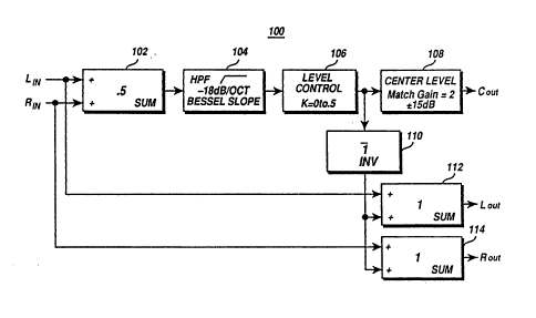
30Figure 1 is a block diagram of the preferred
embodiment of the present invention. In the system 100,
first and second channels of audio information, typically
referred to as left and right side channels, are coupled
to a summing means 102 which generates a co~bined left
plus right (L+R) audio signal. In the preferred practice
of the present invention the summing means 102 limits the
gain of the combined L+R audio signal to .5. The output
,
. ' `~' ;
: ~"
2033679
of summing means 102 is coupled to high pass filter 104
which blocks low frequency information in the combined L+R
audio signal. The high pass filter 104 is preferably a
conventional highly damped Bessel slope filter having a
S slope of approximately -18dB/oct. The output of high pass
; filter 104 is coupled to level control 106 which adjusts
the gain of the combined L+R audio signal to limit the
level of monophonic information in the center channel to a
desired amount. The output of level control 106 is
coupled to a level matching network 108 which allows the
overall gain of the combined L+R audio signal to be
ad~usted to match the sensitivity of the output components
used in the left and right side channels.
The output of level control 106 is further
coupled to phase inverter 110 which shifts the phase of
the combined L+R audio signal by 180 degrees. The output
of phase inverter 110 is further coupled to summing means
112, 114 which sums the inverted, gain limited, high pass
filtered L+R audio signal with the respective left and
right side channel signals to remove a portion of the
monophonic center channel information from the left and
right side channels, thus providing and maintaining a
constant level of monophonic information in the overall
sound field. While the system 100 is shown as
2S incorporating an inverter 110, those skilled in the art
will appreciate that the inverter 110 may be incorporated
in summing means 112, 114 by providing summing means with
inverting and non-inverting inputs.
~ .
The relationship of the respective center and
side channels of the system 100 is defined by the
following equations:
'
L s L - K(L+R)
R - R - K(L+R)
C = 2K(L+R)
.
,
- .
2~33679
where:
L = left side signal
R = right side signal
K = monophonic cancellation gain (limited to K=.5)
2K = center channel output gain
In practice, the variable gain center channel
provides the following output relationships:
CENTER K LEFT RIGHT CENTER SEPARATION
SETTING CHANNEL CHANNEL CHANNEL LIMIT
0% O L R O MAX
50~ .25.875L .875R .25(L+R) 17dB
-.125R -.125L
100% .5.72L .75R .5 (L+R) s.5dB
-.25R -.25L
200% 1.5L-.5R .5R-.5L L+R OdB
(limit)
Referring now to Figure lB, in another
embodiment of the present invention, the system 150
includes means for controlling the "ambience" of a sound
field. For the sake of clarity in the description below,
; 30 items which perform identical functions bear identical
designations. An ambience signal may be thought of as a
side channel difference signal wherein the frequency
response of the difference signal may be modified. After
processing, the ambience signal is injected into the left
and right side channels in a variable amount to achieve a
desired effect. In practice, the ambience signal for the
left side channel comprises a (L-R) difference signal and
ambience signal for the right side channel comprises a (R-
L) difference signal. In the system 150, a left minus
right (R-L) signal is derived by difference signal
generator 152. In the preferred practice of the present
203367~
invention, the gain of the difference signal generator 152
is limited to .5 to prevent clipping distortion of maximum
amplitude input signals at the difference amplifier
output. The output of difference signal generator 152 is
coupled to tone control 154 which alters the frequency
response of the difference signal. The output of tone
control 154 is coupled to level control 156 which controls
the amount of ambience signal added to the respective left
and right side channel signals. The output of level
control 156 is coupled to an inverter circuit 158 which
generates the right minus left (R-L) ambience signal. The
system 150 incorporates three input summing circuits 112',
114' which are essentially identical to summing circuits
112, 114 with the addition of an additional input. In the
system 150, the center channel signal is derived in an
identical manner as the system 100. The processed left
and right side channel signals are generated in a similar
manner as the system 100 wherein summing circuit 112'
sums the output of inverter 110 (which comprises the
inverted or phase shifted center channel signal), the left
side channel signal, and the L-R ambience signal.
Similarly, the summing circuit 114 sums the output signals
of inverter 110, inverter 158 (which comprises the R-L
ambience signal) and the right side channel signal. The
following equations define the relationships between the
~nput and output signals in the system 150.
; C = K(.5L+.SRI
L = (.SJL - .5JR) - K(.5L~.5R) = L - K(.5L + .5R)
R s (.5JR - .5JL) - K(.5L+.5R) = R - K(.5R - .5L)
~'
where:
C = center signal
L = left side signal
R = right side signal
X = monophonic cancellation gain (limited to K =
.5(K= 0 - 5))
,. ~ ,' ... ,. ~ -
. - ~
.
; ~ , ;
i
2033679
J = ambience injection gain (J= (0-3))
A typical installation for the improved audio
system of the present invention is shown in Figure 2. In
S the installation 200, the system 100 typically receives
audio left and right input signals from an audio source
(not shown) such as the output of a cassette deck, compact
disk player, tuner, etc. Depending on the specific
application, other components such as an equalizer or a
10 preamplifier may be inserted in series between the audio
source and the system 100. The system 100 processes the
left and right input signals to generate left side
channel, right side channel and center channel signals
which are amplified by power amplifiers 162-166,
15 respectively. Transducers 168, 170, coupled to the
respective outputs of power amplifiers 162, 170 are
typically of the same size and sensitivity and would
typically be mounted in the doors, side panels, or rear
deck of automobile 172. However, in an automobile,
20 options for locating a center channel transducer are quite
limited. Therefore, the present invention contemplates
the use oS a frequency limited center channel to allow a
reduced size transducer 174 which may be mounted in a
variety of locations such as an automobile dashboard where
25 space is limited. The present invention further provides
a variable gain center channel so that the sensitivity of
transducer 174 can be compensated to match the sensitivity
of transducers 168, 170.
As can be seen in Figure 2, without the center
30 channel transducer 174, each of the passengers in
automobile 172 is located in a position proximate a single
side channel transducer. Thus, stereophonic imaging is
minimized since each listener primarily hears the side
channel closest to the listener. With the addition of the
35 side channel transducer 174, a portion of the signal from
each of the side channels is relocated to the center of
.
. . .
- . -:
- . ,
,., ~,. .
-. - . -. ~:- . ;
. ~ ~
~03367~
the automobile 172 thus improving the image perceived by
both passengers.
Referring now to Fiqure 3A, the system 100
receives left and right audio signals at terminals 202,
204, respectively. Input filters 206, 208, coupled to
terminals 202, 206, respectively, provide noise filtering
and input isolation. Input filter 206 comprises
operational amplifier 218 which is disposed with an
inverting input coupled to input terminal 202 through a
broad bandpass filter formed by resistors 203, 207, and
214, and capacitors 205 and 210. Gain control feedback
resistor 209 and filter capacitor 211 are connected in
parallel between the output and the inverting input of
operational amplifier 218. Input filter 208 is identical
to input filter 206 and it includes resistors 213, 216,
217, 221, capacitors 212, 215, 223 and amplifier 220. The
respective components of input filters 206, 208 are
selected to provide a bandpass filter response of
approximately lHz-200KHz.
The outputs of input filters 206, 208 comprise
inverted left and right (-L,-R) input signals which are
coupled to inverting summing network 102. Summing network
102 generates a composite (L~R) sum signal of the inverted
left and right input signals. Summing network 102
includes resistors 222, 224, resistor 226, capacitor 230
and operational amplifier 228 wherein summing network 102
is configured to provide a gain of approximately .5.
Summing network 102 provides a relatively low impedance to
the input sources to minimize distortion and to scale the
input voltage to preserve the dynamic range in the system.
The output of summing network 102 is coupled to
a voltage follower 103 which comprises operational
amplifier 232 and resistors 234, 235. Voltage follower
103 reduces the gain of the composite L+R signal to
compensate for the gain in following stages. The output
of voltage follower 103 is coupled to the input of high
pass filter 104 through coupling and filter capacitor 242.
2033~7~
11
High pass filter 104 blocks any low frequency information
in the composite L+R signal.
The high pass filter 104 is preferably
configured as a 3rd order steep slope bessel type filter
having a slope of approximately 18 dB/oct. High pass
filter 104 comprises operational amplifier 240, resistor
244, and capacitors 242, 246; and operational amplifier
250, resistors 252, 254, 256, capacitor 258 and
stabilizing capacitor 260. In the preferred practice of
the present invention, resistors 244, 248, 256 may be of
the switc~able dip resistor network type to adapt the
frequency response of the system loo for use with
virtually any type of transducer and amplifier system. In
the preferred practice of the present invention, the
components are preferably selected to provide a cutoff
frequency which may range from 20-350 Hz depending on the
values of resistors 244, 248 and 256 with the frequency
being chosen based on the low frequency characteristics of
the center channel transducer.
Referring now to Figure 3B, the output of high
pass filter 104 is coupled to the input of level control
106 through voltage-to-current converting resistor 262 and
AC coupling capacitor 264 which is selected to pass any AC
signal above lOHz without any significant attenuation.
Level control 106 preferably comprises a 2150A voltage
controlled amplifier (VCA) 266, manufactured by That
Corporation, 15 Strathmore Rd., Natick, MA 01760. VCA
266 receives the current signal generated by resistor 262
and amplifies the current signal under the control of the
voltage produced across resistors 268, 2io which form a
1:50 voltage divider. The voltage produced across
resistors 268, 270 is controlled by NPN transistor 272
which is disposed with its emitter coupled to one terminal
of resistor 270 and its collector coupled to the V+
positive voltage source. The base of transistor 272 is
coupled to control terminal 274 through resistor 276
wherein the voltage on control terminal 274 controls the
203~7~
12
voltage generated across resistors 268, 270, and thus the
gain of VCA 266. The control signal on terminal 274 is
filtered by capacitors 278, 280 and resistor 282. VCA 266
preferably provides a gain sensitivity of 6mv/dB.
Therefore, the signal present on control terminal
preferably varies from 0-6 volts, thus providing a
variable voltage of approximately 0-60mv across resistor
268. This voltage scaling provides a relatively low
impedance at control terminal 274 and minimizes the effect
of any noise present at control terminal 274. It should
be noted that as the voltage across resistor 268
increases, the gain of VCA 266 decreases The present
invention contemplates the use of a +/-15 volt power
supply to provide ample dynamic range capabilities in the
system 100. The -15v voltage source is coupled to VCA 266
through resistor 285 and is adjusted to set the quiescent
operating current of VCA 266. In addition, the adjustable
voltage divider formed by resistors 284, 286, and variable
resistor 288 is adjusted to compensate for symmetry
irregularities in the output signal of VCA 266.
The control voltage coupled to control terminal
274 may be generated by virtually any type of voltage
source. In the preferred practice it is anticipated that
system lOO may be located remotely from a listener. For
example, in an automobile, sound systems are frequently
located in the trunk of the automobile. Since the present
invention anticipates the use of a variable gain center
channel, it is anticipated that the control terminal 274
may be coupled to a remote voltage source 275 which may
be installed in the passenger compartment of an
automobile. One remote voltage source adapted for use
with the present invention is shown in Figure 3C. The
remote voltage source 275 comprises a switch 386 having
terminals 390, 392 and 394, diodes 388, 400, light
emitting diode 402, resistors 404, 406, poteniometer 408
and filter capacitor 410. Resistor 406 and poteniometer
408 are coupled in series between the V+ power supply and
:
~: .
, .
2~3367~
form a variable voltage divider 412 with the output of
voltage divider 412 coupled to control terminal 274
through protection diode 400.
Terminal 390 of switch 386 is also coupled to
the V+ power supply. When terminals 390 and 392 of switch
386 are coupled together, the V+ power supply is coupled
to terminal 274 through protection diode 388. This forces
transistor 272 to conduct fully, thus forcing VCA 266 into
a minimum gain state, effectively disabling the system
100. When terminals 392 and 394 of switch 386 are coupled
together, the V+ power supply is coupled to ground through
light emitting diode 402 and resistor 206. This
illuminates light emitting diode 402 and allows the
voltage on terminal 274 to depend on the position of the
wiper of potentiometer 408, thereby providing adjustable
gain in VCA 266.
Referring again to Figure 3B, the oùtput of VCA
266 is coupled to current-to-voltage converter 290 which
comprises operational amplifier 292, feedback resistor 294
and stabilizing capacitor 296. Current-to-voltage
converter 290 converts the current signal output by VCA
266 into a voltage signal processed by the remainder of
the system 100. The output of current-to-voltage
converter 290 is coupled to the non-inverting input of
center level match circuit 108, and the inverting inputs
o~ summing amplifiers 112, 114 through resistors 332, 352,
respectively.
Center level match 108 provides a nominal gain
of 2 and may be adjusted +/- 15 db to match the system lO0
~D ~V Y~ ~p~ n~ ~p~x~ ~y~e~s ~ic~ ~y ~e ~se~
with t~e system ~D0, F~r examp~e~ in many syste~s, ~arge
speakers and amplifiers may be utilized for t~e left and
right side channels. However, since the center c~annel is
high pass filtered, a smaller transducer may be used in
the center cbannel. ~he nominal gain of the center
channel match 108 is set at 2 so that the overall gain of
the center channel composite signal is unity with the side
~.
-:'
:: `
. " .
. . . . . .
.. . . . ... : . .
- - ~ . .. .
:,: . : :, -
;,
` 2~3367~
channel signal cancellation limited to a gain of .5. The
center channel match 108 may be adjusted to compensate for
difference in the sensitivity in the components used in
the center and side channels thus providing a balanced
sound field in the listening environment. The center
channel match 108 includes operational amplifier 300
wherein the non-inverting input of operational amplifier
300 is coupled to the output current-to-voltage converter
290 through resistor 298. Gain setting resistors 312,
314, 316 are selected to set the nominal gain of
operational amplifier 300 at 2. Capacitor 310 provides
high frequency filtering of the output of operational
amplifier 300 to stabilize the amplifier 300. A
potentiometer 304 is coupled between the respective input
15 terminals of operational amplifier 300 and its wiper i5
commected to ground through resistor 306 and AC coupling
capacitor 308. Potentiometer 304 causes either the input
signal or the feedback signal to be partially shunted to
ground thereby providing a plus or minus 15dB gain
20 ad~ustment of the signal at the output of the amplifier
300. The potentiometer 304 has a center detent to set the
gain to 2 (i.e. 6dB). The output of operational amplifier
300 is coupled to the center channel output terminal 318
through resistor 320 and AC coupling capacitor 322.
25 Capacitor 324 filters noise on center channel output
terminal 318. Load resistor 326 provides a discharging
path for capacitor 322.
The summing amplifiers 112, 114 are configured
as inverting amplifiers which sum the combined L+R center
30 channel signal with the respective inverted left and right
side channel signals to eliminate any additional monaural
information from being added to the overall sound field.
As noted above, the amount of L+~ center channel signal
;cancelled from the side channels is user selectable and is
35 controlled by level control 106. In the preferred
practice of the present invention, the maximum side
channel cancellation is limited to .5, thus providing a r
`' ' ` ~ : '~ '
203367~
minimum center channel separation of 9.5 DB. center
channel separation improves at lesser levels of
cancellation.
The inverted output signal of summing amplifiers
112, 114 comprise the left and right side channel signals
defined by the equations set forth above. The summin~
amplifier 112 comprises operational amplifier 330 wherein
the inverting input of operational amplifier 330 is
coupled to the output of current-to-voltage converter 290
through resistor 332 and to the output of input filter 102
through resistor 333. The non-inverting input of
operational amplifier 330 is coupled to system grounds.
Gain setting resistor 334 and stabilizing filter capacitor
336 are connected in parallel between the inverting input
and output of operational amplifier 330. The output of
operational amplifier 330 is coupled to the left side
channel output terminal 338 through series resistor 340
and AC coupling capacitor 342. Capacitor 344 filters out
noise on channel output terminal 338. Load resistor 346
provides a discharging path for capacitor 344. Similarly,
The summing amplifier 112 comprises operational amplifier
350 wherein the inverting input of operational amplifier
350 is coupled to the output of current-to-voltage
converter 290 through resistor 352 and to the output of
input filter 208 through resistor 353. The non-inverting
input of summing amplifier 114 is coupled to system
ground. Gain setting resistor 354 and stabilizing filter
capacitor 356 are connected in parallel between the
inverting input and output of operational amplifier 350.
~he output of operational amplifier 350 is coupled to the
right side channel output terminal 358 through series
resistor 360 and AC coupling capacitor 362. Capacitor 364
filters noise on right channel output terminal 358. Load
resistor 366 provides a discharging path for capacitor
364.
Referring now to Figure 4A, a portion of the
~ system 150 is shown in schematic form. For the sake of
:
,
..~,
"..
.
203~67~
16
clarity, components which perform identical functions in
the system 100 bear identical designations and are not
further discussed below. In addition to the circuitry of
system 100, the system 150 includes difference signal
S generator 152 for deriving the difference between the left
and right input signals. Difference signal ~enerator 152
includes operational amplifier 502 which is disposed with
its inverting input coupled to the output of input filter
206 (which comprises the -L input signal) through
resistors 504, 506, and its non-inverting input coupled to
the output of input filter 20~ (which comprises the -R
input signal) through resistors 508, 510. Filter
capacitor 514 and load resistor 512 are coupled in
parallel between the non-inverting input of operational
amplifier 502 and system ground. Feed~ack resistor 516
and stabilizing filter capacitor 518 are coupled in
parallel between the inverting input and output of
operational amplifier 502. While the difference signal
generator 152 is coupled to -R and -L input signals, in
practice, by virtue of the input phasing, the output of
difference signal circuit 152 comprises a L-R difference
signal. While various signal inversions may oacur during
the detailed operation of the circuitry of Figures 4A-4D,
the circuit remains functionally equivalent to the circuit
shown in Figure lB.
The output of difference signal generator 152 is
coupled to tone control 154 shown in Figure 4B. The tone
control 154 comprises a three stage circuit having high,
mid, and low range stages 502, 504, and 506, respectively,
disposed in a standard tone control topology wherein the
low-range portion S06 is configured as a low-pass
equalizer, the high frequency stage 502 is configured as a
high-pass equalizer and the mid-range stage 504 is
configured as a simple band-pass equalizer. The high
frequency stage 502 comprises resistor 510, potentiometer
514, resistors 516 and S18 and capacitors 512, 520 which
are selected to provide a variable band pass frequency
;
;',
- .
~.
203~79
response ranging from approximately 5KHz-20KHz, based on
the position of variable resistor 514, with an approximate
center fre~uency of approximately lOKHz and a boost of
approximately l/-13dB. Mid-range stage 504 includes
resistor 522, potentiometer 524, resistors 526 and 524 and
capacitors 528, 532 which are selected to provide a
variable bandpass frequency response ranging from
approximately 300Hz-5KHz, based on the position of
variable resistor 524, with a center frequency of
approximately 2KHz and a boost of approximately +/-13db.
The low-frequency stage 506 comprises resistors 534, 538,
and 544, potentiometer 536 and capacitors 540, 541 which
are selected to provide a a variable frequency response
ranging from approximately 20Hz-300Hz, based on the
position of variable resistor 536, with a center frequency
of approximately 40Hz and a boost of approximately +/-
21dB. The output stage of tone control 154 is formed by
operational amplifier 508 which is disposed with its non-
inverting input coupled to system ground. A stabilizing
filter capacitor 509 is coupled between the output and
inverting input of operational amplifier 508. The outputs
of the respective stages 502, 504, and 506 are coupled to
the inverting input of operational 508 which outputs a
selectively filtered, .5(R-L) difference signal to the
level control 156 shown in Figure 4B.
Referring now to Figure 4C, the output of tone
control 154 is coupled to the input of l-evel control 156.
The level control 156 is essentially identical to the
level control 106, with the exception that the values of
30 resistors 262' and 294' are modified to vary the gain of
VCA 266' from 0-3. As in level control 106, a current to
voltage converter 290' converts the current output of VCA
266' to a voltage signal processed by the remainder of the
~,i system 150. The output of current-to-voltage converter
- 35 290' is coupled to inverting buffer amplifier 158 which
inverts the phase of output of level control 156 to
generate the right channel (L-R) ambience signal.
-i~
.
'
'
2n3367~
Inverting buffer amplifier 158 is a simple amplification
stage including operational amplifier 560, gain control
resistors 562, 564 and stabilizing capacitor 566.
Summing amplifiers 112', 114' are essentially
identical to the summing means 112, 114, with the
addition of input resistors 568, 570 which couple the left
and right channel ambience signals to the summing nodes of
the respective summing amplifiers. Specifically, the
input of summing amplifier 114' is coupled to the output
of buffer amplifier 158 (which comprises the right channel
ambience signal) through resistor 570, and the input of
summing amplifier 112' is coupled to the output of
current-to-voltage converter 290' (which comprises the
; right channel ambience signal) through resistor 568.
15 Therefore, the signals present on terminals 338', 358'
comprise the left and right side channel signal with a
variable amount respective left and right ambience signals
summed therewith, and a portion of the L+R center channel
signal cancelled therefrom.
Figure 4D is a schematic diagram of a remote
control voltage source used for controlling the gain of
VCA's 266, 266' through terminals 274, 274', respectively.
The operation of remote control voltage source 277 is
identical to remote control voltage source 275 with the
exception that an identical switching network comprising
potentiometer 408', resistor 406' diodes 388' and 400' and
capacitor 410' is coupled in parallel the corresponding
components in remote control 275 to generate the control
voltage on terminal 274'.
In summary, an improved audio system for use in
` an automotive environment has been described. The present
invention provides means for deriving a center channel of
audio information in a stereophonic audio system wherein
the center channel is used as a monophonic signal re-
- 35 locator to provide an optimized sound field over a wide
area. In addition, a variable portion of the monophonic
information output in the center channel is cancelled from
, .
.
2~3367~
the respective side channels to maintain the overall
monophonic information in the sound field at a constant
level. In yet another embodiment of the present
invention, a side channel difference signal is derived to
generate left and right ambience signals wherein a
variable amount of ambience signal may be injected in the
side channels and used in conjunction with the center
channel to achieve a desired effect. While the present
invention is disclosed as being primarily designed for use
in an automobile, those skilled in the art will appreciate
that the principles disclosed herein may be applied to
virtually any audio system regardless of the available
listening environment. Accordingly, other uses and
modifications of the present invention will be apparent to
lS persons of ordinary skill in the art without departing
from the spirit and scope of the present invention and all
of such uses and modifications are intended to fall within
the scope of the appended claims.
,.
:.
,;~
'