Note: Descriptions are shown in the official language in which they were submitted.
~033817
DESCRIPTION
The present invention relates to devices for welding
motor-vehicle bodies. In particular, the invention
concerns devices which provide for the welding of
motor-vehicle bodies after they have been assembled
provisionally by the loose connection of their
component parts.
Known devices of the type indicated above generally
comprise a station for welding the bodies, a conveyor
line for transporting the loosely preassembled bodies
to the station, locating means provided at the station
for clamping the component parts of the body in the
correct position for welding, and welding means
provided at the station for welding the component parts
of the body together after they have been clamped by
the locating means.
During the last decade, the automotive industry has
shown an ever greater tendency to use devices of the
aforesaid type which have characteristics of
flexibility, that is, which are adapted to operate on
different body types. In fact, the use of flexible
devices has drastically reduced the investment which
was once necessary in order to bring a new model of car
into production, as well as making the time needed to
adapt the production plant to the new model of car
practically negligible.
As regards the welding means used in the devices of the
type indicated above, the desired characteristics of
flexibility have been achieved by the use of robots
with electrical spot-welding heads, the robots being
programmable in dependence on the specific type of body
to be assembled. X~3381~
As far as the locating means for clamping the component
parts of the bodies in the correct position for welding
are concerned, however, the desired characteristics of
flexibility have been achieved by the use of the
invention which forms the subject of the same
Applicant's German patent No. 2,810,822 and the
corresponding U.S. patent No. 4,162,387.
In the device described in the documents identified
above, the welding station has at least two pairs of
locating frames which can be interchanged rapidly in
the working position, the frames of each pair carrying
locating devices suitable for the configuration of a
respective type of body to be welded. Flexible
welding devices of this type have been produced and
sold by the Applicant to many of the major
motor-vehicle manufacturers in Europe and the United
States. Nevertheless, it is felt that there is a
continuing need for further improvement of these known
devices.
, ,
From a different point of view, there is a need to make
the welding means used in the devices as simple and
cheap as possible. In fact, up to now, the use of
flexible welding stations has generally been preferred
to the use of several welding stations, each dedicated
to a respective type of body to be welded, not only
because the use of several stations takes up more space
but also, and above all, because the cost of the
welding robots makes it preferable to use a single set
of robots which operate equally well on different body
types, rather than respective sets of robots in several
welding stations. Naturally, a simplification of the
~,
f ~ . . ~ . . . . .
welding means could lead to the possib~e033 817
reconsideration of the use of "dedicated" welding
stations and this would give greater choice to
motor-vehicle manufacturers at the design stage, with
the advantage that the best solution can be selected
for the specific case under consideration at any time.
The object of the present invention is to provide a
satisfactory solution to all the problems indicated
above.
In order to achieve this object, the subject of the
present invention is a device for welding motor-vehicle
bodies which have been assembled loosely beforehand,
comprising
a station for welding the body,
a conveyor line for transporting the loosely
preassembled bodies to the station,
locating means provided at the welding station for
clamping the component parts of the body in the correct
position for welding, and
welding means provided at the station for welding
the component parts of the body together after they
have been clamped by the locating means,
characterised in that the welding means comprise a
plurality of laser-welding torches which are associated
with the locating means and are connected to laser
emission means by bundles of optical fibres.
In the present description and in the claims which
follow, the term "laser-welding torch" is used to
indicate an optical head for focussing the laser beam
sent to the head onto one or more welding points.
In a preferred embodiment of the invention, the
;~03~817
locating means comprise a plurality of locating devices
supported by locating frames which also support the
laser-welding torches, each locating frame also
carrying at least one optical distributor device having
an input for connection to a laser source and a
plurality of outputs connected to the laser torches
carried by the locating frame.
To advantage, the invention described above can be used
in flexible welding stations which are intended to
operate on at least two different types of
motor-vehicle body and have at least two pairs of
locating frames suitable for respective body types, the
two pairs of frames being rapidly interchangeable in
the working position in dependence on the type of body
to be welded in the welding station.
In this case, a quick-coupling member is provided for
the optical connection between the optical input of a
particular locating frame and the respective laser
source when the locating frame reaches the working
pos ltion .
A different application of the invention described
above provides for the use of a plurality of dedicated
welding stations, that is, stations which are intended
to operate on respective type of motor-vehicle body,
each welding station having a pair of locating frames
suitable for the respective body type and the laser
emission means being connected to the welding torches
of all the stations by bundles of optical fibres. In
this application, the use of several dedicated stations
does not involve an excessive increase in cost by
virtue of the simplicity with which the welding means
intended to operate in the various stations are
Z03381~
produced.
Further characteristics and advantages of the invention
will become clear from the description which follows,
with reference to the appended drawings, provided
purely by way of non-limiting example, in which:
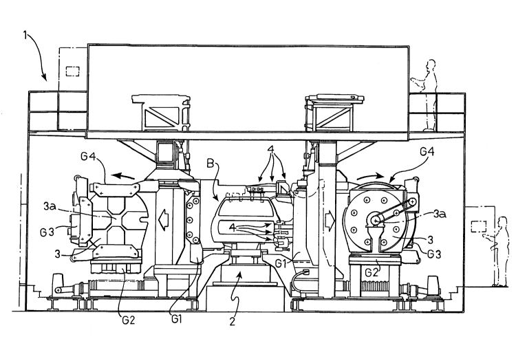
Figure 1 is a schematic view of a welding device
according to the invention,
Figure 2 is a side view of the device of Figure 1,
Figure 3 is a view of a detail of a device of Figure 1
on an enlarged scale,
Figure 4 is a sectional view of a further detail of the
device according to the invention on an enlarged scale,
and
Figure 5 shows a further embodiment of the invention.
Figures 1-3 show, by way of example, the application of
the invention to a flexible welding device of the type
which forms the subject of E ~ pean patent application
No.EP-A-O 351 377 and the corresponding German utility
model DE-U-8 812 396.
With reference to Figures 1-3, a welding station of the
type described in the document identified above is
generally indicated 1. The bodies B to be welded are
supplied to the welding station in succession by means
of a conveyor line 2. Neither the structural details
of the conveyor line 2 nor those of all the other known
components of the welding station 1 are described in
detail below since - as already indicated - these
6 ;~033817
_.
details are supplied in the document identified above.
Moreover, these structural details do not fall within
the scope of the present invention. The bodies B are
supplied to the welding station in a
provisionally-assembled condition which is achieved by
the loose connection of the component parts of the
body. This loose connection can be achieved by means
of bent tongues forming parts of the component parts of
the body. Alternatively, the pallet 2a which moves
along the line 2 and supports a respective body B may
be provided with means for supporting the various
component parts of the body in positions approximating
to their final welding positions.
Still in a manner known from the German utility model
DE-U-8 812 396, a drum 3 is provided on each side of
the welding station and is mounted for rotation about
an axis 3a parallel to the length of the conveyor line
2. Each drum 3 carries on its faces four locating
frames G1, G2, G3 and G4, each of which supports a
plurality of locating devices suitable for a specific
type of motor-vehicle body and intended to clamp the
component parts of a body of the respective type in the
correct position for welding. The details of the
structures of the locating frames and the way in which
they are carried by the respective rotatable drum are
not described in detail in the present description
since they are also known from the prior document
identified above. The same is true of the means for
rotating the rotatable drums 3 about the axes 3a in
order to present a respective pair of locating frames
in positions facing the body in the welding station.
As described in DE-U-8 812 396, each time a body B of a
certain type reaches the welding station, the drums 3
must be in a position such that the two frames G
!'
~0;33817
corresponding to the specific body type face the two
sides of the body. At this point, transverse
translation devices take the two frames G from the
drums and move them towards the two sides of the body
so that the locating devices (indicated 4 in Figures
1-3) can engage the body B and clamp its component
parts in the correct position for welding. Once the
welding has been carried out (by welding means which
will be described below) the clamping devices open and
the two locating frames move outwardly to enable the
welded body to be discharged from the station. If the
next body to reach the welding station is of a
different type from that welded previously, the two
locating frames return to their respective rotatable
drums and the latter are rotated until the new pair of
locating frames are presented in positions facing the
body to be welded, after which the cycle described
above is repeated.
In the prior document cited above, the welding means
provided to the station 1 are constituted by a
plurality of programmable, electrical spot welding
robots and/or by a plurality of welding guns arranged
on the locating frames.
In the welding station according to the invention,
however, the welding means are constituted by a
plurality of laser-welding torches 5 which are
associated with an equivalent number of locating
devices 4 carried by each locating frame G (Figure 4),
and each of which receives a laser beam through a
bundle of optical fibres 6. As illustrated in detail
in Figure 4, each locating device 4 includes two
elements 4a, 4b which are movable between an open
position (not shown) and a closed position in which
8 2033~317
they clamp together two or more pressed-sheet-metal
parts forming parts of the body B to be welded. The
element 4a is fixed to the locating frame G, as is the
respective laser torch 5 which is adapted to focus the
laser beam on the region to be welded, making it pass
through a hole 7 in the element 4a.
In the preferred embodiment shown in Figures 1-3, each
locating frame G has a set of optical distributor
devices 8 each having an optical input for optical
connection to a respective laser source S on the fixed
structure of the welding station and a plurality of
outputs 9 connected by means of bundles of optical
fibres 6 to the laser torches 5 carried by the locating
frame G. The optical distributor devices 8 are not
shown in detail in the present description since they
may be of any known type. For example, optical
distributors of this type are made and sold by Lumonics
JK Industrial Products, together with YAG (~ttrium,
Aluminium, Garnet) laser emitters. In any case, the
structures of the laser emittors and the respective
optical distributors do not fall within the scope of
the present invention.
According to the invention, the welding station has a
plurality of quick-coupling devices 10 (Figures 2, 3)
which enable the optical connection of the inputs of
the distributor devices 8 carried by a particular
locating frame G to the laser sources S when the
locating frame reaches the working position
corresponding to the engagement of the locating devices
4 with the body to be welded.
The quick-coupling device 10 comprises a slide 11
guided for vertical sliding on a guide 12 carried by
g X033817
the fixed structure 13 of the welding station 1 (Figure
3). The slide 11 is moved vertically by a screw 14
which engages a nut 15 fixed to the slide 11. The
screw 14 is rotated by an electric stepping motor 15
supported by the fixed structure 13. A bracket 16 is
fixed to the slide 11 and supports a cylindrical body
17 which is guided for sliding on a vertical tubular
shaft 18 whose upper end is connected to the output 19
of the laser source S.
The lower end of the cylindrical body 17 comprises a
tubular connecting element 20 with a flared conical
mouth 20a which is adapted to be coupled to a conical
appendage 21 of the distributor device 8, coaxial with
the input of the distributor device 8.
When the locating frame G is moving towards its working
position in the welding station, the slide 11 is in the
raised position. When the locating frame G has
reached its working position, the conical appendage 21
is substantially aligned with the axis 18a of the
tubular shaft 18. Once the frame G has stopped, the
slide 11 is lowered so that the tubular element 20 fits
onto the conical appendage 21. Any misalignment
between the two coupling elements 20, 21 is corrected
by virtue of the conical coupling since the
distributor device 8 is supported by the locating frame
G with the interposition of two perpendicular slides
22, 23. In other words, the device 8 is free to slide
relative to the slide 23 along a line perpendicular to
the plane of Figure 3, the slide in turn being slidable
relative to the frame G in the directions indicated by
the arrows A in Figure 3. The conical coupling forces
the distributor 8 and the appendage 21 to assume the
correct position. Once the coupling device is in the
., . . . . . . . ,~ ., , . .. .. ~ .
20~3~817
`_
operative position, the laser beam emitted by the
source s can reach the laser torches 5 carried by the
frame G by passing through the tubular shaft 18, the
cylindrical body 17, the optical distributor device 8
and the bundles of optical fibres 6. When the welding
is completed, if the next body to be welded is of a
different type, the slide 11 of each quick-coupling
device 10 is raised to enable the locating frames G to
be changed.
Naturally, the use of the quick-coupling device 10 also
enables the application of welding by means of laser
torches 5 to flexible welding stations OL types
different from that illustrated purely by way of
example, in Figures 1-3, for example,of the type
described in the same Applicant's German patent No. 2
810 822 and in the corresponding U.S. patent No. 4 162
387.
As indicated in the introduction to the present
description, the invention also enables and makes
economically advantageous a solution which provides for
a plurality of welding stations dedicated to the
various types of body to be welded. Figure 5 shows
schematically, in plan, two welding stations 30A, 30B
for operating on two different types of motor-vehicle
body. Each welding station has a single pair of
locating frames G provided with locating devices
suitable for the configuration of the respective body
type. A conveyor line 31 brings the bodies Bl and B2
of the two different types envisaged to the welding
stations 30A, 30B in succession. Obviously, the
bodies Bl stop only in the welding station 30A, whilst
the bodies B2 stop only in the welding station 30B.
Each locating frame G has a plurality of laser torches
1 1 Z~)338~7
5 associated with respective locating devices 4, in a
manner similar to that illustrated in Figure 4. The
laser torches 5 of the two pairs of frames G of the two
stations 30A, 30B are connected by bundles of optical
fibres 6 to a single laser emission system 35 which, in
the embodiment illustrated, comprises a plurality of
laser sources 36 each provided at its output with an
optical distributor device 37 whose outputs are in turn
connected by bundles of optical fibres 6 both to laser
torches 5 of the station 30A and to laser torches 5 of
the station 30B.
Naturally, the principle of the invention remaining the
same, the details of construction and forms of
embodiment may be varied widely with respect to those
described and illustrated purely by way of example,
without thereby departing from the scope of the present
invention.