Note: Descriptions are shown in the official language in which they were submitted.
METHOD OF AND SYSTEM FOR PRESSING SHEET GLASS
BACKGROUND OF THE INVENTION
1. Field of the Invention:
The present invention relates to a method of and a
system for pressing a sheet of glass into a highly curved
sheet of glass which has a relatively small radius of
curvature.
2. Description of the Prior Art:
Some front and rear window glass sheets on automo-
biles are, curved to relatively small radii of curvature.
One known apparatus for bending a sheet of glass to a small
radius of curvature is disclosed in Japanese Patent
Publication No. 61(1986)-28611.
The disclosed apparatus has convex and concave
molds for bending a glass sheet therebetween. The concave
mold is composed of a central pressing mold member, and left
and right pressing mold members. After the glass sheet is
clamped between the central pressing mold member and the
convex mold, the glass sheet is pressed to a curved shape
between the central, left, and right mold members and the
convex mold.
The convex mold and.the concave mold, which is
divided into the mold members, are however incapable of suf-
ficiently stretching a central region of the glass sheet, so
that the pressed glass sheet tends to have an insufficiently
- 1 -
2~~~~~~
curved configuration. Tf the glass sheet were forcibly
curved to correct insufficiently curved configuration, then
the glass sheet would be liable to crack due to undue
pressure. If the entire surface of the glass sheet were
heated to high temperature, then a press mark would be left
on the peripheral edges of the glass sheet by surface mate-
rials on the molds.
According to a solution disclosed in Japanese
Patent Publication No. 61(1986y-17775, only the central
region of a glass sheet is heated to a higher temperature
than the other regions thereof, so that only the central
region of the glass sheet can be curved to a greater degree.
However, it has proven highly difficult to control the
localized heating accurately.
SUMMARY OF THE INVENTION
In view of the afor$said problems of the conven-
tional methods and apparatus for pressing a sheet of glass
to curved shape, it is an object of the present invention to
provide a method of and a system for easily pressing a sheet
of glass to a highly curved sheet of glass having a rela-
tively small radius of curvature without developing defects
such as cracks or the like in the sheet of glass.
According to the present invention, there is pro-
vided a method of pressing a glass sheet, comprising the
steps of heating the glass sheet nearly to a softening point
thereof by passing the glass sheet through a heating
- 2 -
furnace, clamping only a peripheral edge of the heated glass
sheet between first and second molds, and pressing a third
mold against a central region of the glass sheet with the
peripheral edge thereof clamped, thereby to project the cen-
tral region from one side to the other side thereof, whereby
the glass sheet is pressed to a curved shape.
The above method may be carried out by a system for
pressing a sheet glass, comprising a heating furnace for
heating the glass sheet nearly to a softening point, and a
pressing apparatus for clamping only a peripheral edge of
the heated glass sheet at opposite sides thereof, and pro-
jecting only a central region of the glass sheet, which is
surrounded by the clamped peripheral edge thereof, from one
of the sides to the other side thereof, whereby the glass
sheet is pressed to a curved shape.
The above and further objects, details and edvan-
tages of the present invention will become apparent from the
following detailed description of preferred embodiments
thereof, when read in conjunction With the accompanying
drawings.
BRIEF DESCRIPTION OF THE DRAWINGS
FIG. 1 is a fragmentary front elevational view of
a system for pressing a sheet of glass to curved shape
according to a preferred embodiment of the present
invention;
FIG. 2 is a perspective view of preliminary shaper
rolls as a feed means capable of preliminarily shaping a
- 3 -
2~~3~~~
heated sheet of glass in the pressing system shown in FIG.
1;
FIG. 3 is an enlarged front elevational view of a
central mold member and left and right side mold members of
a convex mold of a pressing apparatus in the pressing
system;
FIG. 4 is an enlarged side elevational view of the
central mold member and front and right side mold members of
the convex mold of the pressing apparatus;
FIG. 5 is a bottom view of the convex mold of the
pressing apparatus;
FIG. 6 is a perspective view of a concave mold of
the pressing apparatus;
FIG. 7(A) is a front elevational view showing the
pressing apparatus in a first phase of operation for gress-
ing a sheet of glass;
FIG. 7(B) is a front elevational view showing the
pressing apparatus in a second phase of operation for press-
ing a sheet of glass;
FIG. 7(C) is a front elevational view showing the
pressing apparatus in a third phase of operation for press-
ing a sheet of glass; and
FIG. 8 is a bottom view of a modified convex mold
according to the present invention.
DETAILED DESCRIPTION OF THE PREFERRED EMBODIMENTS
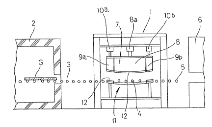
FIG. 1 schematically shows a pressing system which
includes an apparatus, generally denoted at 1, for pressing
~~~J~~~
a glass sheet G to a highly curved shape. The glass sheet G
is heated nearly to a softening point: thereof by a heating
furnace 2 located downstream of the pressing apparatus 1,
while the glass sheet G is traveling through the heating
furnace 2. The heated glass sheet G is transferred by feed
rolls 3 onto in-mold rolls ~ in the pressing apparatus 1, in
which the glass sheet G is pressed to a desired curved
shape. After the glass sheet G is pressed, it is delivered
into a cooling device 6 by feed rolls 5. The feed rolls 3,
the in-mold rolls 4, and the feed rolls 5 jointly serve as a
feed mechanism for feeding the glass sheet G successively
through the heating, pressing, and cooling stations.
As shown in FIG. 2, each of the feed rolls 3 is in
the form of a preliminary shaper roll comprising a core 3a
curved to a shape which is preliminarily to be given to the
glass sheet G, and a heat-resistant sleeve 3b rotatably fit-
ted over the core 3a. Therefore, the glass sheet G is prel-
iminarily shaped to a preliminary shape by the feed rolls 3
while being delivered by the feed rolls 3. When the prelim-
inarily shaped glass sheet G is subsequently pressed by the
pressing apparatus 1, the glass sheet G can be pressed to a
large curvature without undue stresses because the glass
sheet G does not undergo a large abrupt change in shape.
fihe pressing apparatus 1 generally comprises an
upper convex mold 7 having a convex shaping surface and a
lower concave mold 8 having a concave shaping surface which
~o~~~~~
is substantially complementary to the convex shaping surface
of the upper convex mold 7. As shown 1n FIG. 5, the upper
convex mold 7 is composed of a central mold member a and a
peripheral mold assembly 9 disposed around the central mold
member 8. The peripheral mold assembly 9 comprises front
and rear side mold members 9a, 9b (FIG. 4) which are spaced
from each other in the direction in which the glass sheet G
is fed, and left and right side mold members 9c, 9d (FIG. 3)
spaced from each other in a direction substantially normal
to the direction in which the glass sheet G is fed. The
side mold members 9a, 9b, 9c, 9d can independently be moved
vertically by respective cylinder units 10a, lOb, lOc, 10d
(actuator means). The central mold member 8 can also inde-
pendently be moved vertically by a cylinder unit Sa
(actuator means). As shown in FIG. 6, the lower concave
mold 11 is in the form of a fixed unitary ring mold for sup-
porting only the peripheral edge of the glass sheet G. In
the illustrated embodiment; therefore, the upper convex mold
7 is vertically movable by the cylinder units ea and l0a
through lOd, whereas the lower concave mold 11 is vertically
fixed in position.
The shaping surface of each of the molds 7, 8 is
covered with a surface material layer 12 attached thereto,
as shown in FIG. &. The surface material layer 12 may be
made of a woven or felt layer of glass fibers, ceramic
fibers, metallic fibers, aramid fibers, or the like.
~o~~~~
To press the glass sheet G, the glass sheet G is
heated nearly to its softening point while being passed
through the heating furnace 2. The heated glass sheet G is
preliminarily shaped by the feed rolls 3 and transferred
onto the in-mold rolls 4 in the pressing apparatus 1. Then,
the in-mold rolls 4 are lowered to place the glass sheet G
on the lower concave mold il. Alternatively, the lower con-
cave mold 11 may be elevated to receive the glass sheet G
from the in-mold rolls 4.
Substantially at the same time, the cylinder units
10a, lOhb are extended to lower the front and rear side mold
members 9a, 9b to clamp the glass sheet G at its front
and rear peripheral edge portions between the front and rear
side mold members 9a, 9b and the lower concave mold or ring
mold 11, as shown in FIG. 7(A) (first phase of operation of
the pressing apparatus 1).
Then, as shown in FIG. 7(B), the cylinder units
10c, lOd, ea are extended to lower the side mold members 9c,
9d and the central mold member e, thus bending the overall
surface of the glass sheet G (second phase of operation of
the pressing apparatus 1). At this time, the central mold
member 8 is further lowered after the entire peripheral edge
of the glass sheet G is fixed or clamped by the side mold
members 9a, 9b, 9c, 9d and the lower concave mold 11.
Stated otherwise, prior to further downward movement of the
central mold member 8, the left and right peripheral edge
portions of the glass sheet G are clamped between the side
mold members 9c, 9d of the upper convex mold member 7 and
the lower concave mold member 11 (by this time, the front
and rear peripheral edge portions of the glass sheet G have
already been clamped between the side mold members 9a, 9b
and the lower concave mold 11). Therefore, the entire
peripheral edge of the glass sheet G is completely pressed
by the side mold members 9a, 9b, 9c, 9d and the lower con-
cave mold 11 before the central region of the glass sheet G
is pressed between the central mold member 8 and the lower
concave mold 11.
Thereafter, as shown in FIG. 7(C), the central mold
member 8 is further lowered to stretch and project the cen-
tral region of the glass sheet G further downwardly from an
upper side to a lower side thereof, thus pressing the glass
sheet G to a desired curved shape (third phase of operation
of the pressing apparatus 1). Then, the glass sheet G is
delivered by the feed rolls 5 into the cooling device 6, in
which the glass sheet S is quickly cooled and hence
tempered.
In FIGS. 7(A), 7(B), and 7(C), the side mold member
9b is omitted from illustration. While the lower concave
mold 11 is shown as baing a ring mold, it may be a full-
surface mold for contacting the entire lower surface of the
glass sheet S.
In the above embodiment, in order to clamp the
peripheral edge of the glass sheet G between the convex and
_ g
convex molds 7, 8 before the central mold member 8 is
lowered, the front and rear side mold members 9a, 9b are
lowered, and thereafter the left and right mold members 9c,
9d are lowered. However, the four side mold members 9a, 9b,
9c, 9d may simultaneously be lowered to clamp all the
peripheral portions of the glass sheet G between the convex
and concave molds 7, 11 at the same time.
Furthermore, while the peripheral mold assembly 9
of the upper convex mold 7 is constructed of the four side
mold members 9a, 5b, 9c, 9d, the peripheral mold assembly
may comprise, as shown in FIG. 8, a unitary upper ring mold
member 9' which neatly mate with the unitary lower ring mold
11. In operation, before the central mold member 8 is
lowered, the upper ring mold member 9' is lowered in its
entirety to clamp the entire peripheral edge of the glass
sheet G between itself and the lower concave mold 11. The
upper ring mold member 9' is simpler in construction and
allows a quicker pressing process than the peripheral mold
assembly 9 shown in FIG. 5.
With the present invention, as described above, the
peripheral edge of the glass sheet is first clamped between
the peripheral edge of the convex mold and the concave mold,
and then the central mold member of the convex mold is
pressed against the central region of the glass sheet and
pushed further to curve the central region of the glass
sheet. Therefore, a sheet of glass can be pressed accu-
- 9 -
rately to a highly curved shape without wrinkles or cracks.
The sheet of glass thus curved is suitable for use as front
and rear window glass sheets for automobiles.
Although there have been described what are at pre-
sent considered to be the preferred embodiments of the pre-
sent invention, it will be understood that the invention may
be embodied in other specific forms without departing from
the essential characteristics thereof. The present embodi-
ments are therefore to be considered in all aspects as
illustrative, and not restrictive. The scope of the inven-
tion is indicated by the appended claims rather than by the
foregoing description.
- 10 -