Note: Descriptions are shown in the official language in which they were submitted.
~ 203~17~
TITLE OF THE INVENTION
Optical Coupler and Method of Producing The Same
BACRGROUND OF THE INVENTION
Field of the Invention
The present invention relates to an optical coupler
and a method of producing the same, and more particularly,
it relates an optical coupler which comprises a plurality of
all plastic fibers.
Description of the Prior Art
The Japanese Patent Laid-Open Gazette No. 62-153906
discloses an optical coupler (See Fig. 1). The optical
coupler is formed by a plurality of optical fibers 1 each of
which has a core la and a clad lb surrounding the core la.
More precisely, intermediate portions 2 of the optical
fibers 1 are dipped in sulfuric acid to remove the clads
therefrom, following which the optical fibers 1 are bundled
up while the intermediate portions thereof being in contact
with each other. Then, the e~posed cores la are thermally
fused together.
The prior art is employed with glass fibers in which
a core la is made of glass material such as quartz, and
therefore requires further improvement when employed with
all plastic fibers in which a core la is made of plastic
material. This is because: Cores la are thermally fused
after bundled up in intermediate portions 2. This causes
~.
20341~
the cores la in intermediate portions 2 to shrink upon.
Consequently, optical loss such as excess loss increases.
In addition, clads lb near the intermediate portion 2 would
also be heated during fusing, causing serious problems in
the all plastic fibers 1. The problems with the all plastic
fibers 1 include deformation due to the molten clads lb and
deteriorated characteristics resulting from diffusing the
clad material into the cores la. Diffusion of the clad
material is particularly problematic because it largely
increases optical loss.
SUMMARY OF THE INVENTION
The present invention is directed to a method of
producing an optical coupler. The method comprises the
steps of: preparing two all plastic fibers each of which has
a core extending in a predetermined direction; placing the
all plastic fibers in contact with each other over a
predetermined length; and applying ultrasonic vibration to
the contacting portion of the all plastic fibers so as to
bond the cores with each other at the contacting portion.
The present invention is also directed to an optical
coupler. The optical coupler comprises: a plurality of all
plastic fibers disposed in branching off relation, each of
the all plastic fiber having a core; and a plurality of
bonding portions at which two cores of the all plastic
fibers are bonded with each other, wherein each downstream
~ ~3~17~
portion of the all plastic fiber in the upstream side is
fused to an upstream portion of the all plastic fiber in the
downstream side at every bonding portion.
The present invention is also directed to a method
of producing the above optical coupler. The method
comprises the steps of: preparing a plurality of all plastic
fibers each of which has a core; placing the all plastic
fibers in branching off relation, each downstream portion of
the all plastic fiber in the upstream side being in contact
with an upstream portion of the all plastic fiber in the
downstream side; and applying ultrasonic vibration to the
contacting portions of the all plastic fibers so as to bond
the cores with each other at every contacting portion.
The present invention is also directed to an optical
coupler. The optical coupler comprises: a first all plastic
fiber; a plurality of second all plastic fibers disposed in
branching off relation from a downstream portion of the
first all plastic fiber, each downstream portion of the all
plastic fiber in the upstream side being in contact with an
upstream portion of the all plastic fiber in the downstream
side; a plurality of third all plastic fibers disposed in
branching off relation from an upstream portion of the first
all plastic fiber, each downstream portion of the all
plastic fiber in the upstream side being in contact with an
upstream portion of the all plastic fiber in the downstream
203417~
side, each of the first to third all plastic fibers having a
core; and a plurality of bonding portions at which two cores
of the all plastic fibers are bonded with each other,
wherein each downstream portion of the all plastic fiber in
the upstream side is fused to an upstream portion of the all
plastic fiber in the downstream side at every bonding
portion.
The present invention is also directed to a method
of producing the above optical coupler. The method
comprises the steps of: preparing a first all plastic fiber;
placing a plurality of second all plastic fibers in
branching off relation from a downstream portion of the
first all plastic fiber, each downstream portion of the all
plastic fiber in the upstream side being in contact with an
upstream portion of the all plastic fiber in the downstream
side; placing a plurality of third all plastic fibers in
branching off relation from an upstream portion of the first
all plastic fiber, each downstream portion of the all
plastic fiber in the upstream side being in contact with an
upstream portion of the all plastic fiber in the downstream
side, each of the first to third all plastic fibers having a
core; and applying ultrasonic vibration to the contacting
portions of the all plastic fibers so as to bond the cores
with each other at every contacting portion.
The present invention is also directed to an optical
2~3~ ~5
coupler. The optical coupler comprises: a first and a
second optical coupler each of which has 2n (n 2 1) input
fiber branches and 2 output fiber branches, the input fiber
branches serving as an input port, the output fiber branches
serving as an output port; and a plurality of bonding
portions at which two cores of the all plastic fibers are
bonded with each other, wherein the output fiber branches of
the first optical coupler are fused to the output fiber
branches of tne second optical coupler with a one-to-one
correspondence, whereby the bonding portions are formed.
The present invention is also directed to a method
of producing the above optical coupler. The method
comprises the steps of: preparing a first and a second
optical coupler each of which has 2n (n 2 1~ input fiber
branches and 2 output fiber branches, the input fiber
branches serving as an input port, the output fiber branches
serving as an output port; placing the output fiber branches
of the first optical coupler in contact with the output
fiber branches of the second optical coupler with a one-to-
one correspondence; and applying ultrasonic vibration to the
contacting portions of the all plastic fibers so as to bond
the cores with each other at every contacting portion.
Accordingly, the first object of the present
invention is to provide a low-e~cess-loss optical coupler.
The second object of the present invention is to
20341~
provide a method of producing a low-excess-loss optical
coupler.
The third object of the present invention is, on
attainment of the second object, to simplify manufacturing
process of the low-excess-loss optical coupler.
These and other objects, features, aspects and
advantages of the present invention will become more
apparent from the following detailed description of the
present invention when taken in conjunction with the
accompanying drawings.
BRIEF DESCRIPTION OF THE DRAWINGS
Fig. 1 is a view of a conventional optical coupler;
Fig. 2 is a view of an apparatus for manufacturing
an optical coupler according to the present invention;
Figs. 3A, 3B and 4 are perspective views explaining
the embodiments of the present invention, respectively;
Fig. 5 is a schematic view of an optical coupler
produced in accordance with the embodiments of the present
invention;
Fig. 6 is a schematic view of an optical coupler
according to a fifth embodiment of the present invention;
Figs. 7A to 7C are schematic views showing the
manufacturing procedure for the optical coupler of Fig. 6,
respectively;
Fig. 8 is a schematic view of an optical coupler
203417~
.
with the distribution number N of "6";
Fig. 9 is a schematic view of an optical coupler
with the distribution number N of "8";
Figs. 10 and 11 are schematic views of optical
couplers according to a si}~th embodiment of the present
invention, respectively;
Figs. 12A to 12C are schematic views showing the
manufacturing procedure for an optical coupler according to
a seventh embodiment of the present invention, respectively;
Figs. 13A to 13C are schematic views showing the
manufacturing procedure for an optical coupler according to
an eighth embodiment of the present invention, respectively;
Figs. 14A to 14C are schematic views showing the
manufacturing procedure for an optical coupler according to
a ninth embodiment of the present invention, respectively;
Figs. 15 and 16 are views schematically showing
propagation of light in a coupling segment, respectively;
Figs. 17 and 18 are perspective views of a hollow
cover, respectively; and
Fig. 19 is a perspective sectional view of the
hollow cover of Figs. 17 and 18.
DESCRIPTION OF THE PREFERRED EMBODIMENTS
A. Apparatus for Manufacturing Optical Coupler
Fig. 2 is a view of an apparatus for manufacturing
an optical coupler according to the present invention. The
20~417~
term "the apparatus" refers to the apparatus for
manufacturing an optical coupler. Figs. 3A, 3B and 4 are
explanatory perspective views of the apparatus,
respectively.
The apparatus includes a jig 20 for supporting two
all plastic fibers 10 and 11, the all plastic fibers 10 and
11 being formed by cores lOa and lla surrounded by clads lOb
and llb, respectively. The term "fiber" refers to the all
plastic fiber. The jig 20 comprises a lower welding mold 21
and an upper welding mold 22, which are engageable with each
other (Fig. 3A or 3B). The lower and the upper mold 21 and
22 are made of metal or resin.
The lower welding mold 21 has a groove 21a on its
upper surface, and the upper welding mold 22 has a groove
22a on its bottom surface, the grooves 21a and 22a extending
in a direction X. First, the fibers 10 and 11 extending in
the X-direction are placed in parallel juxtaposition to each
other. Then, the upper welding mold 22 is moved upward
while moving the welding mold 21 downward in such a manner
that the fibers 10 and 11 are mounted in the grooves 2la and
22a, respectively. The fibers 10 and 11 are held in direct
contact with each other in a predetermined position when the
upper welding mold 22 engages with the lower welding mold
21.
The elements identified by the reference numbers 23
-- 8 --
203417~
and 24 are spacers made of elastic material such as silicone
rubber. The spacers 23 and 24 are inserted between the
lower welding mold 22 and the upper welding mold 21 to
prevent relative inclination of the lower and the upper
welding mold 21 and 22 as well as dislocation of the fibers
10 and 11.
In addition, the apparatus is provided with an
ultrasonic welding device 30 (Fig. Z). A vibrator 31 of the
ultrasonic welding device 30 is connected to a top surface
22b of the upper welding mold 22. The vibrator 31 vibrates
in a vertical direction during the ultrasonic welding device
30 is operating. The vibration energy of the vibrator 31
would be applied to a contacting segment of the fibers 10
and 11 through the upper welding mold 22.
The apparatus further includes a pressure
application device (not shown) for applying specified
pressure to the ultrasonic welding device 30 from an upper
direction. When the pressure application device is
activated, specified pressure is applied to the fiber 11
through the ultrasonic welding device 30 and the upper
welding mold 22, whereby the fiber 11 is pressed against the
fiber 10.
B. 2 x 2 Channeled Optical Coupler
B-1. First Embodiment
Now, e~planation is given on the method of producing
g
203417~
an optical coupler from two fibers made of non-crosslinked
polymethyl methacrylate with the apparatus. First, an
operator places fibers 10 and 11 in the predetermined
positions (Fig. 3A) and gives a command through an operating
panel not shown to start production. In response to this,
the jig 20 holds the two fibers 10 and 11 in accordance with
a instruction from a control part (not shown) which controls
the whole apparatus.
Thereafter, the pressure application device is
operated to apply specified pressure to the fiber 11 through
the ultrasonic welding device 30 and the upper welding mold
22, so that the fiber 11 is pressed against the fiber 10.
Ne~t, the ultrasonic welding device 30 is operated, and the
contacting segment of the fibers 10 and 11 receives
vibration energy while being under predetermined pressure.
Then, at initial stage of this, the clads lOb and llb in the
contacting segment are destroyed and pushed away in a
direction Y perpendicular to the X-direction (Fig. 2),
following which the cores lOa and lla are partially fused
together. This results in formation of a coupling segment
41 and four fiber branches 42 to 45 each of which e~tends
therefrom longitudinally to the fibers 10 and 11.
On completion of the partial coupling of the cores
lOa and lOb, the control part gives a stop command, to
thereby stop the ultrasonic welding device 30 and the
-- 10 --
~ 203417~
pressure application device and further to take out thus
produced optical coupler 40A (Fig. 5) from the jig 20. As
in Fig. 5, the optical coupler 40A has 2 x 2 channels; that
is, the fiber branches 42 and 43 each of which is to serve
as an input port (or an output port) and the fiber branches
44 and 45 each of which is to serve as an output port (or an
input port).
E~amplary measurement of an optical coupler produced
in such manner will now be discussed. The optical coupler
was produced under certain conditions. The conditions are
as follows:
Pressure = 10 kgf;
Vibration Frequency = 15 kHz;
Vibration Amplitude = 40 ,um;
Vibration Application Time = 0.5 sec.; and
Length of Coupling Segment 41 (i.e., Q) = 20 mm.
An optical power measurement system was used for
evaluation of the characterstics of the optical coupler 40A.
The optical power measurement system includes a light source
for outputting red light and a detector for measuring energy
of light passing through an optical device. In the optical
power measurement system, red light of 11.74 ~W is received
by the detector when one end of a clad-coated fiber, cut to
the same length as the optical coupler 40A, is connected to
the light source while other end thereof connected to the
~ 2~3~17~
detector. More particularly, fiber branches 42 to 45 were
individually connected to the light source of the optical
power measurement system, the fiber branches 42 to 45 acting
as a first to a fourth input or output port, respectively.
Then, output values at fiber branches in the opposite side
to the connected fiber branch were measured; for e~ample,
output values at the fiber branches 44 and 45 (the third and
the fourth port) are measured when the fiber branch 42 (the
first port~ is connected to the light source. Thereafter,
e~cess loss and divergence ratio were obtained from the
measured values. Table 1 gives the results.
Table 1
Input: first port second port third port fourth port
Output:
first port - - 5.236 ~W 4.767 ~W
second port - - 4.037 ~W 5.020 ~W
third port6.520 ~W 3.279 ~W - -
fourth port3.048 ~W 6.446 ~W
Loss (dB) 0.89 0.82 1.03 0-79
Divergence
Ratio 2.1:1.0 1.0:2.0 1.3:1.0 1.0:1.1
~ 203~17~
For example, when red light is given from a LED to
the fourth port (fiber branch 45), the output values at the
first port (fiber branch 42) and the second port (fiber
branches 43) are 4.767 ~W and 5.020 ~W, respectively, and
the divergence ratio of the optical coupler is 1.0:1.1.
The e~cess loss EL is obtained as:
4.767 + 5.020
EL - -10 log - 0.79 (dB)
11.74
Thus, an optical coupler 40A having low excess loss
can be produced according to the production method of the
present invention.
As described above, the following effects are
obtainable according to the first embodiment:
(1) So-called ultrasonic welding is adopted in
producing the optical coupler 40A according to the first
embodiment, so that there is no thermal effect on the fibers
and 11 and hence no increase of excess loss due to
shrinkage of the fibers 10 and 11 caused by heating. In
fact, as in Table 1, an optical coupler 40A having low
excess loss were successfully produced according to the
first embodiment.
(2) There is no deformation of the fibers 10 and 11
caused by heat or diffusing clad material into the cores lOa
and lla, for the reasons being the same as above. Hence,
- 13 -
2~3~17~
the optical coupler 40A can be produced without
deteriorating characteristics thereof.
(3) The optical coupler 40A offers simplicity and
lower producing cost since no attempts are made to remove
any of the clad prior to fusing the fibers 10 and 11.
(4) Time required for coupling fibers 10 and 11 is
not more than 1 second (0.5 sec. in the first embodiment).
Thus, the optical coupler 40A can be produced in a very
short time.
B-2. Second Embodiment
The following description represents the method of
producing an optical coupler from two polycarbonate fibers
using the apparatus. First, clads lOb and llb of fibers 10
and 11 are removed over a predetermined length,
respectively. Removal of the clads is done by a chemical
process using an etchant such as methyl methacrylate or by a
mechanical process such as grinding. Thus, cores lOa and
lla of the fibers 10 and 11 are partially exposed,
respectively. Such exposed portions will be hereinafter
referred to as "the exposed core segments lOa' and lla'" for
the sake of convenience.
An operator places the fibers 10 and 11, which has
gone through the clad removal, in the specified positions
(Fig. 3B). Then, the operator instructs to start production
through the operating panel (not illustrated), responding to
- 14 -
203417~
.
this, a control part not shown for controlling the whole
apparatus starts operating. Thus, a jig 20 holds the two
fibers 10 and 11 according to a command from the control
part.
Subsequently, a pressure application device is
operated to apply predetermined pressure to the fiber 11
through an ultrasonic welding device 30 and the upper
welding mold 22, to thereby press the exposed core segment
lla' into contact with the exposed core segment lOa'.
Following this, the ultrasonic welding device 30 applies its
vibration energy to the contacting segment of the exposed
core segments lOa', llb'. During this, the pressure
application device keeps applying the predetermined pressure
to the contacting segment. Thus, the exposed core segments
lOa' and llb' are fused together, whereby a coupling segment
41 and four fiber branches 42 to 45 are formed.
On completion of the coupling of the exposed core
segments lOa' and llb', the control part operates the
ultrasonic welding device 30 and the pressure application
device to stop. Finally, an optical coupler 40B produced as
above is taken out from the jig 20 (Fig. 5). As in Fig. 5,
the optical coupler 40B is identical to the optical coupler
40A in structure.
Examplary measurement of an optical coupler 40B
produced in the above manner will now be discussed. The
- 15 -
203~17S
optical coupler 40B was produced under specified conditions,
the conditions being:
Length of Exposed Core Segment = 20 mm;
Pressure = 10 kgf;
Vibration Frequency = 15 kHz;
Vibration Amplitude = 40 ~m;
Vibration Application Time = 0.5 sec.; and
Length of Coupling Segment 41 (i.e., Q) - 20 mm.
The aforementioned optical power measurement system
was used for evaluation of the characteristics. Precisely,
a fiber branch 42 of the optical coupler 40B was connected
to the light source of the optical power measurement system,
the fiber branch 42 serving as a first input or output port.
Then, light of a wavelength of 660 nm (P42 = 13 ,uW) from a
LED was entered to the fiber branch 42 acting as the first
input port, and the output values P44 and P45 were measured,
the values P44 and P45 being at the ends of the fiber
branches 44 and 45, which serve as a third and a fourth
output port, in the opposite side to the fiber branch 42
(the first input port), respectively. The output values P44
and P45 were 3.95 ~W and 4.55 ,uW, respectively. Hence, the
divergence ratio was 1.0:1.1, and the excess loss EL is:
3.95 + 4.55
EL = -10 log . = 1.845 ~dB~
13.00
- 16 -
203~17~
Further, light (P43 = 13 uW) from the LED was
inputted at the end of the fiber branch 43 (the second input
port) to measure output values P44 and P45 at the ends of
the fiber branches 44 and 45 (the third and the fourth
output port), which are situated in the opposite side to the
fiber branch 43 (the second input port). The output value
P44 was 3.73 ~W and the value P45 was 4.87 uW. Hence, the
divergence ratio was 1.0:1.3, and the excess loss EL is:
3.73 + 4.87
EL = -10 log = 1.794 (dB)
13.00
Thus, as can be seen from these results, an optical
coupler 40B having low excess loss can be produced according
to the production method of the present invention. In
addition, the optical coupler 40B serves as an optical
device having nearly equal distribution.
In the second embodiment, the fiber branches 42 and
43 act as an input port while the fiber branches 44 and 45
act as an output port. It must be noted here that the
respective fiber branches 42 to 45 are an input port as well
as an output port.
As described before, in the second embodiment, the
optical coupler 40B is produced by the so-called ultrasonic
welding, which accompanies no heating. Owing to absence of
thermal effect, the fibers 10 and 11 do not shrink, and
- 17 -
~ 2~3~7~
therefore, excess loss would not be deteriorated. This is
the same as in the first embodiment. Thus, an optical
coupler 40B having low excess loss can be produced according
to the second embodiment. Further, the characteristics of
the optical coupler 40B are not disgraced during the
production. Still another advantage in producing the optical
coupler 40B is largely reduced production time; that is, the
time required for coupling the fibers 10 and 11 is not more
than 1 second, to be precise, 0.5 second in the second
embodiment.
Here, it is iterated that in the second embodiment
the optical coupler 40B is formed by the fibers 10 and 11
made of polycarbonate plastic, which is generally known as
so-called heat resistant fiber. This allows the optical
coupler 40B to be enough use in rather high temperature,
thus bringing about one more advantage in addition to those
recited above.
B-3. Third Embodiment
In the following part, explanation is given on the
method of producing an optical coupler from two fibers of
crosslinked polymethyl methacrylate with the apparatus.
Substantially the same as the second embodiment, the
production method will not be explained in detail here.
Examplary measurements of three optical couplers 40C
produced in a similar manner as the second embodiment will
- 18 -
2~3~ 75
now be discussed. The respective optical couplers 40C were
produced under the following conditions:
Length of Exposed Core Segment = 20 mm;
Pressure = 10 kgf;
Vibration Frequency = 15 kHz;
Vibration Amplitude = 40 um;
Vibration Application time = 0.5 sec.; and
Length of Coupling Segment 41 (i.e., Q) = 20 mm.
The aforementioned optical power measuring system
was used for evaluation of the characteristics of the
optical couplers 40C. Precisely, a fiber branch 42 of each
of the optical couplers 40C was individually connected to
the light source of the optical power measurement system.
Then, red light ~= 17 ~W) from a LED is injected into the
fiber branch 42 in order to measure output values at the
ends o the fiber branches 44 and 45, which are in the
opposite side to the fiber branch 42. Further, a fiber
branch 43 of each of the optical couplers 40C was in turn
connected to the light source. Then, output values at the
ends of the fiber branches 44 and 45 were measured,
similuarly to the above. Then, the excess loss EL and the
divergence ratio were calculated. Tables 2 to 4 show the
results with respect to the three optical couplers 40C.
-- 19 --
~34~7S
Table 2
Input: first port second port
Output:
third port 3.06 ~W 7.29 ~W
fourth port 7.35 ~W 3.31 ,uW
Loss 2.13 dB 2.05 dB
Divergence
Ratio 1 : 2.4 1 : 2.2
Table 3
Input: first port second port
Output:
third port 3.21 ~W 6.72 ~W
fourth port 6.09 ~W 3.36 ~W
Loss 2.62 dB 2.27 dB
Divergence
Ratio 1 : 1.9 1 : 2.0
Table 4
Input: first port second port
Output:
third port 3.78 ~W 5.38 ~W
fourth port 4.92 ~W 3.58 ~W
Loss 2.91 dB 2.78 dB
Divergence
Ratio 1 : 1.3 1 : 1.5
- 20 -
203417~
Referring to the tables 2 to 4, the first to the
fourth ports indicate the fiber branches 42 to 45 acting as
an input or an output port, respectively.
As can be seen from the tables, an optical coupler
40C having low loss can be attained according to the
production method embodied by the third embodiment.
Thus, effects similar to that of the second
embodiment are obtainable in the third embodiment.
B-4. Fourth Embodiment
In the first to the third embodiments, two fibers 10
and 11, each of which comprises a core and a clad
surrounding the core, were fused together by a predetermined
length, whereby the respective optical couplers 40A, 40B and
40C are produced. However, this is not exclusive or
limiting. It is also possible to produce an optical coupler
from fibers which are not covered with a clad. Description
below is examplary production method using non-clad fibers.
First, a mi~ed monomer is made by using benzoyl
pero~ide as an initiator, methyl methacrylate as a preform,
and ethylene glycol dimethacrylate (= concentration of 1.0
weight percent) as a crosslinked agent. The mi~ed monomer
is then sealed in a Teflon tube having an inner diameter of
1.0 mm. Thereafter, the monomer in the Telfon tube is
polymerized under heat in a deo~idized atmosphere. Thus, a
thermosetting resin fiber is obtained, which includes
- Z1 -
~ 20341~S
nothing but a core. Remaining steps of production method
are similar to the first embodiment: First, two fibers thus
produced are prepared; Ne~t, predetermined pressure is
applied to the fibers in order to press them with each other
over a predetermined length; Then, ultrasonic vibration is
applied to the contacting segment of the fibers; whereby the
cores of the fibers are fused together in the contacting
segment. This results in formation of a coupling segment
and four fiber branches. Consequently, a 2 x 2 channeled
optical coupler is produced. The coupling segment and the
outer periphery of the cores are coated with a resin having
low refractive index, e.g., prepolymer, in order to prevent
leakage of light from the fibers.
Having examined in a manner similar to described
before, an optical coupler produced as above e~hibited
results of about 3dB e~cess loss and about 1.0:1.5
divergence ratio. Hence, a quality optical coupler having
small excess loss is obtainable.
B-5. Other Embodiment
Further, the divergence ratio can be changed
properly by adjusting the pressure applying to the
contacting segment of the fibers. For example, when an
optical coupler 40A is produced according to the production
method above while varying pressure within the range of 5
kgf to 10 kgf (other conditions are the same as above), the
~ 20~7~
divergence ratio can vary in the range of 8:1 to 1:1.
C. 1 x N Channeled Optical Coupler
Fig. 6 is a schematic view of an optical coupler 50A
according to a fifth embodiment of the present invention.
The optical coupler 50A is produced by ultrasonic welding.
Production of the optical coupler 50A is as follows: As in
Fig. 7A, first, fibers 10 and 11 are placed in partial
juxtaposition to each other and in contact with each other.
Before proceeding to further explanation, one thing must be
made clear; that is, the fibers 10 and 11 are illustrated as
being separated in Fig. 7A only for clearity of the
positional relations therebetween. The fibers 10 and 11 are
contacting with each other in contacting segment thereof
(i.e., portion encircled by dashed-and-dotted line).
Now turning back to the explanation, the fibers lO
and 11 are then fused together by ultrasonic welding in the
contacting segment, whereby a coupling segment 51a and two
fiber branches 52a and 52b, each of which extends from the
coupling segment 51a, are formed (Fig. 7B).
Next, a fiber lZ is placed approximately in parallel
to the fiber branch 52a extending from the coupling segment
51a. Thereafter, the fiber branch 52a and the fiber 12 are
partially fused together by ultrasonic welding (i.e.,
portion encircled by dashed-and-dotted line in Fig. 7B),
whereby a coupling segment 51b and two fiber branches 52a
- 23 -
2~34~ 7~
and 52d extending from the coupling segment 51b are formed
(Fig. 7C). Likewise, a fiber 13 is then placed
approximately in parallel to the fiber branch 52b, followed
by partial fusing together (portion encircled by dashed-and-
dotted line in Fig. 7C) by ultrasonic welding, in order to
form a coupling segment 51c (Fig. 6) and two fiber branches
52b and 52e extending from the coupling segment 51c. Thus,
the optical coupler 50A is produced.
Hence, an optical signal injected into the fiber
branch 52c serving as an input or an output port is divided
into two at the coupling segment 51a to be guided to the
coupling segments 51b and 51c. The optical signal guided to
the coupling segment 51b is then further divided into two
signals to be outputted at the fiber branches 52a and 52d
serving as an input or an output port. Another optical
signal guided to the coupling segment 51c is likewise
divided into two signals thereat, to be outputted at the
fiber branches 52b and 52e serving as an input or an output
port. Thus, the optical coupler 50A is capable of
transmitting one optical signal to four nodes (fiber
branches) at one time. In other words, the optical coupler
50A acts as a 1 x 4 channeled optical coupler.
It is iterated that the divergence ratios of the
coupling segments 51a to 51c can be changed by adjusting
pressure to be applied onto the fibers during ultrasonic
- 24 -
2~3417~
welding. Hence, by properly setting divergence ratios of
the coupling segments 51a to 51c, a desired distribution of
optical signal energy is available at the ends of the fiber
branches 52a, 52b, 52d and 52e.
In addition, the optical coupler 50A is capable of
coupling optical signals injected into fiber branches 52a,
52b, 52d and 52e at coupling segments 51a, 51b and 51c. The
optical signals coupled at the coupling segments would be
then divided and discharged from fiber the branches 52c and
52f.
Examplary measurement of an optical coupler 50A will
now be discussed. Production of the optical coupler 50A of
Fig. 6 is carried out as follows: First, the coupling
segment 51a was produced by ultrasonic welding as above.
The conditions employed in the ultrasonic welding are
Pressure = 10 kgf,
Vibration Frequency = 15 kHz,
Vibration Amplitude = 40 ~m,
Vibration Application Time = 0.5 sec., and
Length of Coupling Segment 51a (i.e., Qa) = 20 mm.
Following the production of the coupling segment
51a, ultrasonic welding is then applied to portions 10 mm
away from the coupling segment 51a under the same
conditions, to thereby form coupling segments 51b and 51c.
Consequently, the optical coupler 50A is produced
- 25 -
2~3~7~
eventually.
Then, the characteristics of the optical coupler 50A
are examined with an optical power measurement system as
above. More particularly, the end of the fiber branch 52c
is connected to the light source of the optical power
measurement system. Thereafter, light (P52C = 16 ,uW) from
the light source is injected into the fiber branch 52c,
thereby to measure output values P52a, P52b, P52d and P52e
at the ends of the fiber branches 52a, 52b, 52d and 52e.
The output values P52a, P52b, P52d and P52e were 1-5 ~W, 1-7
~W, 1.5 ,uW and 1.3 ,uW, respectively. Thus, it is observed
that the inputted optical signal was distributed
approximately equally. The excess loss EL is obtained as:
1.5 + 1.7 + 1.5 + 1.3
EL = -10 log = 4.25 (dB)
16
In the fifth embodiment, one optical signal can be
distributed to four fiber branches, i.e., distribution
number N is rr4. rr The distribution number N can be changed
depending on the number of coupling segments. For instance,
if the coupling segment 51c is not produced in the above
embodiment, the distribution number N would be rr3.rr In this
case, an optical signal entered at the fiber branch 52c
would be expelled at the ends of the fiber branches 52a, 52b
and 52d with a proper distribution ratio. If, on the other
- 26 -
~ 20~417S
hand, the number of coupling segments is increased, the
distribution number N would grow by the increased number of
the coupling segments. More particularly, a plurality of
fibers are placed in branching off relations. Then,
ultrasonic welding is applied to each contacting portion in
which a downstream portion of a fiber in the upstream side
with respect to the contacting portion is placed in parallel
and in contact with an upstream portion of a fiber in the
downstream side with respect to the contacting portion.
Fig. 8 is a schematic view of an optical coupler 50B
with the distribution number N of "6l'. In producing the
optical coupler 50B, si}~ fibers 10 to 15 are prepared, and
are then arranged as in Fig. 8 wherein the fibers are
gradually branching off from the upstream side (left-hand
side of the figure3 toward the downstream side (right-hand
side of the figure). At the first contacting segment 51a,
the downstream portion llDw of the fiber 11 and the upstream
portion 10up of the fiber 10 are then fused together by
ultrasonic welding in a manner as above. Here, brief
e~planation is given on the terms "upstream side" and
"downstream side." These terms are used for describing the
relative positional relation between fibers which face each
other. In Fig. 8, according to this terminology, the fiber
11 is placed in the upstream side while the fiber 10 being
placed in the downstream side such that they are in contact
- 27 -
~ 2~3~17~
with each other over a predetermined portion. The facing
portions llDw and 10up of the fibers 11 and 10 are referred
to as "downstream portion" and "upstream portion,"
respectively, for the purpose of clear distinction. The
terms will adhere to the remaining explanations of the
specification.
After the welding of the first contacting segment
51a, two fibers are fused together by ultrasonic welding
individually at the second to the fifth contacting segment
51b to 51e. Therefore, one fiber branch is formed in the
upstream side (left-hand side of the figure) while six fiber
branches being formed in the downstream side (right-hand
side of the figure), the fiber branches serving as an onput
or an output port. Consequently, a 1 x 6 channeled optical
coupler 50B is produced and similar effects to described
before can be attained.
Fig. 9 is a schematic view of an optical coupler 50C
with the distribution number N of "8." In Fig. 9, eight
fibers 10 to 17 are placed in branching off relations such
that they gradually diverge from the upstream side (left-
hand side of the figure) toward the downstream side (right-
hand side of the figure). At each one of the contacting
segments 51a to 51e, downstream portion of the fiber in the
upstream side and upstream portion of the fiber in the
downstream side are fused together by ultrasonic welding
- Z8 -
~ 203417~
similarly as described above. In consequence, an optical
coupler 50C in which the distribution number N is 8 and
similar effects to described before can be attained.
D. M x N Channeled Optical Coupler
Fig. 10 is a schematic view of an optical coupler 60
according to a sixth embodiment of the present invention.
The optical coupler 60A is produced as follow: First, four
fibers 10 to 13 are prepared, and are then disposed as in
Fig. 10, similarly to the fifth embodiment. Thereafter, two
fibers are fused together by ultrasonic welding individually
at a first to a third contacting segment 61a to 61c. Thus,
an optical coupler having four fiber branches 62a to 62d in
the downstream side is produced, which is identical to the
optical coupler 50A of Fig. 6. Following this, three fibers
14 to 16 are further prepared, and are then arranged as in
Fig. 10 wherein the three fibers 14 to 16 are gradually
branching off from the upper portion of the fiber 11 toward
the upstream side (left-hand side of the figure~. Then, at
each of contacting segments 61d to 61f, two fibers are fused
together by ultrasonic welding, whereby four fiber branches
62e to 62h are formed in the upstream side. Consequently,
an optical coupler 60A is produced, which has four fiber
branches serving as an input port and four fiber branches
serving as an output port.
Although the above embodiment describes the 4 x 4
- ?9 -
~3~
channeled optical coupler 60A in which the number M of input
ports is "4" and the number N of output ports is -411, the
numbers M and N can be changed depending on the number of
coupling segments. For instance, after an optical coupler
having four fiber branches 62a to 62d in the downstream side
is produced, five fiber 14 to 18 are arranged as in Fig. 11
wherein the fibers 14 to 18 are gradually branching off from
the upper portion of the fiber 11 toward the upstream side
(left-hand side of the figure). Then, at each of contacting
segments 61d to 61h, two fibers are fused together by
ultrasonic welding, whereby six fiber branches 62e to 62j
are formed in the upstream side. Consequently, an optical
coupler 60B is produced, in which the number M is ll6ll.
E. 2m x 2m Channeled Optical Coupler
E-1. Seventh Embodiment
Fig. 12C is a schematic view of an optical coupler
according to a seventh embodiment of the present
invention. In producing the optical coupler 70, first, 2 x
2 channeled optical couplers 40a and 40b produced as above
are prepared and placed in parallel (Fig. 12A). Then,
middle portions of the fiber branches 44 are fused together
by ultrasonic welding (Fig. 12B). This results in formation
of the coupling segment 71 and the fiber branches 72a, 72b
which extend therefrom longitudinally to the fibers, that
is, in the X-direction. Likewise, middle portions of the
- 30 -
203~17~
fiber branches 45 are fused together (Fig. 12C), whereby the
coupling segment 73 and the fiber branches 74a, 74b are
formed. Thus, the optical coupler 70 is produced which has
22 x 22 channels; that is, 22 fiber branches 42, 43, 42 and
43 which are to serve as an input port and 2 fiber branches
72a, 72b, 74a and 74b which are to serve as an output port.
It is needless to say that the fiber branches 42, 43, 42 and
43 can be used as an output port while using the fiber
branches 72a, 72b, 74a and 74b as an input port.
E-2. Eighth Embodiment
Fig. 13C is a schematic view of an optical coupler
according to an eighth embodiment of the present
invention. In producing the optical coupler 70, first, 2 x
2 channel optical couplers 70a and 70b produced as above
are prepared. The optical couplers 70a and 70b are then
placed in parallel (Fig. 13A). Thereafter, middle portions
of the fiber branches 73a are fused together by ultrasonic
welding (Fig. 13B). This results in formation of coupling
segment 81 and fiber branches 82a, 82b each of which extends
therefrom in the X-direction. Likewise, middle portions of
the fiber branches 74a, the fiber branches 74b and the fiber
branches 72b are individually fused together (Fig. 13C),
whereby coupling segments 83, 85, 87 of Fig. 13C are formed,
respectively. Thus, the optical coupler 80 is produced
which has 23 x 23 channels; that is, 23 fiber branches 42,
- 31 -
2~3417~
43, . . which are to be either an input or an output port
and 2 fiber branches 82a, 82b, ... which are to be either
an output or an input port.
E-3. Ninth Embodiment
Fig. 14C is a schematic view of an optical coupler
90 according to a ninth embodiment of the present invention.
In producing the optical coupler 90, first, 23 x Z3
channeled optical couplers 80a, 80b produced as above are
prepared. The optical couplers 80a, 80b are then placed in
parallel (Fig. 14A). Thereafter, middle portions of the
fiber branches 83a are fused together by ultrasonic welding
(Fig. 14B). This results in formation of coùpling segment
91a and fiber branches 92a, 92b each of which e~tends
therefrom longitudinally to the fibers, that is, in the X-
direction. Likewise, fiber branches corresponding to each
other are fused together at middle portions thereof, whereby
coupling segments 91b to 91h of Fig. 14C are formed,
respectively. Thus, the optical coupler 90 is produced
which has 24 x 24 channels; that is, 24 fiber branches 42,
43, ... which are to be either an input or an output port
and 2 fiber branches 92a, 92b, ... which are to be either
an output or an input port.
E-4. Other Embodiment
The seventh to the ninth embodiments are focused on
22 x 22, ~3 x 23, 24 x 24 channeled optical couplers.
2B3~l 7~
.
However, application of the present invention is not limited
to this, but rather other applications are also available:
For e~ample, two optical couplers each having 2 x 2
channels are prepared, similarly to the seventh to the ninth
embodiments. Each optical coupler has 2n (n ~ 4) input
fiber branches to be an input port and 2n output fiber
branches to be an output port. Then, welding is conducted
to couple middle portions of the output fiber branches of
one optical coupler and the middle portions corresponding
thereto of the other optical coupler. Thus, a optical
coupler which has 2n 1 x 2n 1 channels is produced.
E-5. Operations of Seventh Embodiment
Fig. 12C also shows the operation of the optical
coupler 70 according to the seventh embodiment. The optical
coupler 70, a 2 x 2 channeled type coupler, has four fiber
branches 42, 43, 42 and 43 to serve as an input port ~or
output port) and another four fiber branches 72a, 72b, 74a,
74b to serve as an output port ~or input port). In the
following description, the fiber branches will be termed as
follows for clarity of explanation: The fiber branches 42,
43, 42 and 43 will be referred to, from the top in the
figure, as the first port CH1, the second port CH2, the
third port CH3 and the fourth port CH4, while the fiber
branches 72a, 72b, 74a, 74b will be referred to, from the
top in the figure, as the fifth port CH5, the sixth port
- 33 -
2 ~
CH6, the seventh port CH7 and the eighth port CH8.
In Fig. 12C, an optical signal S1 inputted at the
first port CH1 is guided to the coupling segment 41a where
it would be divided into optical signals S2 and S3.
The optical signal S2 is then guided to the coupling
segment 71 where it would be divided into optical signals S4
and S5 to be eventually outputted at the fifth and the si~th
ports CH5 and CH6. The optical signal S3, on the other
hand, is guided to the coupling segment 73 where it would be
divided into optical signals S6 and S7 to be similarly
outputted at the seventh and the eighth ports CH7 and CH8.
The energies of the optical signals S2 to S7 vary
depending on the divergence characteristics of the coupling
segments, however, information contained therein are e~actly
the same with that of the optical signal S1. Hence, in the
optical coupler 70, energies of optical signals outputted at
the ports CH5 to CH8 can be distributed as desired as a
matter of course, but also can be appro~imately equaled to
each other, by properly setting the divergence
characteristics of the coupling segments 41a, 41b, 71 and
73. The divergence characteristics of the coupling segments
can be changed by adjusting lengths of the coupling segments
or press,ure applied during welding.
The optical coupler 70 performs similar operations
to above even when an optical signal is inputted to any port
- 34 -
~ 203~1 7~
other than the first port CH1. The input optical signal is
divided and outputted, at four ports in the opposite side to
the port which received the input signal, in the form of
four optical signals each containing the information of the
input optical signal.
Being easy to be assumed from the operations of the
optical coupler 70, the operations of the optical couplers
80 and 90 are not particularly explained here.
E-6. Examples of Seventh to Ninth Embodiments
Examplary measurements of optical couplers 70, 80
and 90, each of which comprises a plurality of fibers of non-
crosslinked polymethyl methacrylate, will now be discussed.
An optical coupler 70 was produced by forming
coupling segments 41a, 41b, 71 and 73 by ultrasonic welding
under the following conditions:
Pressure = 10 kgf;
Vibration Frequency = 15 kHz;
Vibration Amplitude = 40 ~m;
Vibration Application Time = 0.5 sec.; and
Length of Welding Mold =20 mm.
The aforementioned optical power measurement system
was used for evaluation of the characteristics of the
optical coupler 70. In detail, a first port CH1 was
provided with light of a wavelength of 660 nm (P1 = 15.4 ~W)
from the light source of the optical power system. The
- 35 -
~ 203417~
optical power system then received light emerged from a
fifth to an eighth ports CH5 to CH8 situated in the opposite
side to the first port CH1. Thus, output values P5 to P8 at
the ports CH5 to CH8 were measured. The results are the
output values P5 of 2.8 ~W, P6 of 2.5 ,uW, P7 of 4.1 ~W and
P8 f 2.7 ~W. The divergence ratio is:
1.1 : 1.0 : 1.6 : 1.1.
The excess loss EL is:
2.8 + 2.5 + 4.1 + 2.7
EL = -10 log = 1.0 (dB)
15.4
Next, description is given on characteristics of a
optical coupler 80 with 23 x 23 channels.
Coupling segments were formed by ultrasonic welding
under the same conditions as above for the sal~e of
e~amination of the characteristics.
In this examination, the same optical power
measurement system as above was similarly employed. In more
detail, a first port CH1 was provided with light of a
wavelength of 660 nm (optical power P1 = 15.5 ~W) from the
light source (Fig. 13C). Output values P9 to P16 were then
measured which emerged from the fiber branches 82a, 84a,
86a, 88a, 82b, 84b, 86b, 88b situated in the opposite side
to the first port CH1. The results are Pg of 1.32 ~W, P1o
of 1.33 ~W, P11 of 1.28 ~W, P12 of 1.30 ~W, P13 of 1.20 ~W,
- 36 -
~3~7~
P14 of 1.35 ,uW, P15 of 1.30 ~W and P16 of 1.50 ~uW. The
excess loss EL is:
1.32 + ... + 1.50
EL = -10 log = 1.65 (dB)
15.5
Next, description is given on characteristics of a
optical coupler 90 with 24 x 24 channels.
Coupling segments were formed by ultrasonic welding
under the same conditions as above for the sake of
examination of the characteristics.
In this examination, the same optical power
measurement system as above was similarly employed. In more
detail, a first port CH1 was provided with light of a
wavelength of 660 nm (optical power P1 = 15.5 ~W) from the
light source (Fig. 14C). Output values P17 to P32 were then
measured which emerged from the fiber branches 92a to 99a,
92b to 99b situated in the opposite side to the first port
CH1. The results are P17 of 0.68 ~W, P18 of 0.55 ~W, P19 of
0.52 ~W, P20 of 0.61 ~W, P21 of 0.60 ~W, P22 of 0.56 ~W, P23
of 0.49 ~W, P24 of 0 55 ,uW, P25 f 0.48 ,uW, P26 of 0.61 ~W,
P27 of 0.59 ~W, P28 of 0.58 ~W, P29 of 0.55 ~uW, P30 of 0.60
,uW, P31 of 0.60 ~W and P32 of 0.52 ,uW. The excess loss EL
i s :
0.68 + ... + 0.52
EL = -10 log = 2.31 (dB)
15.5
- 37 -
2034175
E-7. Effect of Seventh to Ninth Embodiments
The optical couplers according to the seventh to the
ninth embodiments are made only of fiber in the embodiments,
which enables equal coefficients of thermal expansion at any
portion of the optical couplers. This permits the
respective portions to expand (or shrink) at the same rate
even with changes in temperature of environment. Thus, the
optical couplers are free from severe changes in
characteristics thereof caused by changes in room
temperature. In addition, coupling segments with enough
strength can be attained since the coupling segments are
formed either by ultrasonic welding or thermal welding.
F. Hollow Cover for Optical Coupler
It is a common practice to employ resin molding to
form a coupling segment of an optical coupler for
reinforcing the strength of the coupling segment. Resin
molding is necessary not only for this purpose, but also for
fixing angles between the fiber branches and the coupling
segment. In the optical coupler 40A according to the first
embodiment, for example, resin molding fixes angles between
the coupling segment 41 and the respective fiber branches 42
and 43 which are to form the first and the second port
thereof, as well as angles between the coupling segment 41
and the respective fiber branches 44 and 45 which are to
serve as the third and the fourth port. Hence, resin
- 38 -
203~17~
molding of a coupling segment 41 has grave significance.
However, there remains a problem when resin molding
is applied to coupling segment of an optical coupler
produced in the above manner; namely, excess loss increase.
Examplary measurement of an optical coupler 40A
which has a coupling segment 41 molded with epoxy resin will
now be discussed. Table 5 shows excess losses.
Measurements of the excess losses are as the same as
described before.
Table 5
Input:first port second port third port fourth port
Output:
firsr port - - 4.597 ~W 4.194 ~W
second port - - 3.208 ~W 4.622 ~W
third port6.029 ~W 2.771 ,uW
fourth port2.535 ~W 5.996 ~W
Loss (dB) 1.37 1.27 1.77 1.24
Mean values of the excess losses of Table 1 and
Table 5 are calculated, respectively. The mean value of
when not employing resin molding is 0.88 dB, whereas that of
when employing resin molding is 1.41 dB. In this case,
resin molding has increased excess loss by 0.53 dB. This is
- 39 -
-
203417~
because input light, which is in propagation mode (i.e.,
transmissible) when resin molding is not conducted, would be
converted into radiation mode due to resin molding.
If resin molding is not conducted, incident light
proceeds within a coupling segment 41 as shown in Fig. 15.
In Fig. 15, light L1 entering at a certain angle of
incidence proceeds while successively totally reflected at
the interface between an air layer ~refractive index nO = 1)
and a clad 41b (refractive index n1 > nO). In contrast,
when resin molding is employed, as shown in Fig. 16, the
light L1 enters an epo~y resin 5 across the interface
between a clad 41b and the epo~y resin 5. This is because
the refractive inde~{ n2 f the epoxy resin 5 is generally
larger than the refractive inde~ nO of the air layer.
Hence, the proportion of light converted from the
propagation mode into the radiation mode increases as the
refractive index n2 increases. Accordingly, the excess loss
stemming from resin molding increases.
The following method is proposed in order to enhance
the strength of a coupling segment while simultaneously
fixing angles of fiber branches without increasing excess
loss.
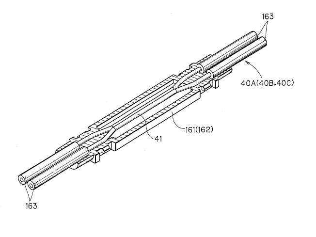
Figs. 17 and 18 are perspective views of a hollow
cover according to the present invention. As in Fig. 17, a
hollow cover 60 comprises a pair of cover members 161 and
- 40 -
1- 2039L175
162 made of epogy resin. When engaged with each other, the
cover members 161 and 162 would serve as one completed
member. The upper face of the cover member 161 and the
lower face of the cover member 162 are formed so as to
conform to the configuration of an optical coupler 40A. The
cover members 161 and 162 are moved upward and downward,
respectively, into engagement after an optical coupler 40A
is placed in a predetermined position (Fig. 18). In
consequence, the optical coupler 40A is enclosed by the
cover members 161 and 162, and therefore, is protected.
Hence, even if external pressure is exerted to the optical
coupler 40A, this hollow cover 160 prevents the pressure
from acting further on the coupling segment 41. In
addition, fiber branches covered with a holding sheath 163
would be firmly held between the cover members 161 and 162.
This allows the branch angles of the fiber branches to be
fixed.
On the other hand, the coupling segment 41 would be
kept wrapped up in an air layer (Fig. 19). Hence, in
theory, variation of excess losses does not occur. In order
to verify this, excess losses were measured in the same
manner as above after protecting the optical coupler 40A by
the hollow cover 160. Table 6 shows the results.
- 41 -
2034175
Table 6
Input: first port second port third port fourth port
Output:
first port - - 5.222 ~W 4.736 ~W
Second port - - 4.040 ~W 5.025 ~W
third port 6.525 uW 3.263 ,uW
fourth port 3.040 ,uW 6.435 ~W
Loss (dB) 0.89 0.82 1.03 0.80
Calculating from Table 6, the mean value of the
losses is 0.88 dB. Thus, even if the coupling segment 41 is
covered with the hollow cover 160, the characteristics of
the optical coupler 40A are not changed.
In the embodiment above, cover members 161 and 162
are made of epoxy resin. However, it is appreciated that
this is not limiting.
Further, the hollow caver 160 can be applied to all
of coupling segments of the above optical coupler.
Although the present invention has been described
and illustrated in detail, it is clearly understood that the
same is by way of illustration and example only and is not
to be taken by way of limitation. The spirit and scope of
the present invention should be limited only by the terms of
the appended claims.
- 42 -