Note: Descriptions are shown in the official language in which they were submitted.
2034298
-- 1
LIOUID JET RECORDING HEAD
FIELD OF THE INVENTION AND RELATED ART
The present invention relates to a liquid jet recording
apparatus wherein recording is effected by ejecting droplets
of liquid through an ejection outlet, using thermal energy.
Prior Art
In a liquid jet recording apparatus using the thermal
energy, an electro-thermal transducer is used to eject
droplets of the liquid. The thermal energy produced thereby
is effective to vaporize the liquid and form a bubble, by
which a pressure is produced to eject the liquid in the form
of a droplet.
Such a system is advantageous, among others, in that the
ejection outlets can be disposed at a high density so that
the high resolution images can be recorded.
The high density arrangement, however, requires narrow
liquid passages communicating with the ejection outlets. The
narrow passages have higher inertance and impedance, with the
result of longer time period for the liquid to refill the
passage from the liquid supply side. This prevents increase
of the recording speed.
By the reduction of the length of the passage, the
refilling time period can be reduced. If, however, this is
done, the speed and the volume of the ejected liquid reduces,
with the result that the stable recording is not possible.
Japanese Laid-open pat. Application No. 204352/1985
proposes, in an attempt to solve this problem to stabilize
the liquid ejection with the short passage, that an ink jet
recording head has a resistance to reduce flow of the liquid
in the passage to the supply side from the electro-thermal
transducer.
20342~8
-- 2
Japanese laid-open pat. Application No. 87356/1988
proposes, in an attempt to increase a percentage of the
energy of the bubble contributable to the ejection of the
liquid, that the cross-sectional area of the passage adjacent
to the electro-thermal transducer increases toward the
ejection outlet.
Japanese laid-open pat. Application No. 195050/1988
proposes that the top wall of the passage is made higher in
the neighborhood of the electro-thermal transducer than the
other portion so that the liquid passage is not blocked by
the bubble (Japanese laid-open pat. Application No.
139970/1981).
In the system disclosed in Japanese laid-open pat.
Application No. 204352/1985, there arise the following
problems:
(1) The difficulty in the provisions of the resistances
in the passages increases with the increase of the density of
the nozzles and with the increase of the number of the
ejection outlet of the recording apparatus.
(2) If the resistance is too remote from the electro-
thermal transducer, the effects of the resistances reduces;
and if it is too near, the produced bubble develops to the
clearance between the wall of the passage and the resistance
with the result of the reduction of the effects of the
resistances.
Therefore, the optimum design of the configuration,
dimension and position or the like is difficult, and even if
the optimum design is made, the effects are not sufficient.
The method disclosed in Japanese laid-open pat.
Application No. 87356/1988 involves a problem that the multi-
nozzle structure is difficult, although the energy use
efficiency is improved. In this method, the cross-sectional
.... .
2034298
-- 3
area of the passages is increased toward the ejection side
with the result of the thin wall between the adjacent
passage. If the wall is too thin, the strength may become
insufficient, or the pressure of the bubble is transmitted to
the adjacent passages, and therefore, the proper ejection is
not expected. For these reasons, the method is not suitable
to increase the high density arrangement or to increase the
number of the nozzles.
According to the arrangement disclosed in the Japanese
laid-open pat. Application No. 95050/1988, the liquid passage
is not blocked by the bubble, and therefore, the liquid can
be sufficiently supplied, so that the ejection is stabilized.
However, the publication simply states that the top wall of
the passage is made higher at the energy applying portion
than the other portion.
SUMMARY OF THE INVENTION
Accordingly, it is a principal object of the present
invention to provide a liquid jet recording head having
plural ejection outlets disposed at a high density.
It is another object of the present invention to provide
a liquid jet recording head capable of ejecting a liquid
droplet at a high speed.
It is a further object of the present invention to
provide a liquid jet recording head capable of ejecting a
liquid droplet having a sufficient volume.
It is a further object of the present invention to
provide a liquid jet recording head capable of refilling the
ejected liquid at a high speed.
It is a further object of the present invention to
provide a liquid jet recording head wherein an impedance at
the side downstream of a pressure producing portion in a
liquid passage is different from that of the upstream side
~T
- _ 4 _ 2034298
with respect to the flow of the liquid upon the liquid
ejection, in consideration of the liquid flow upon ejection
and during refilling liquid supply.
According to the embodiment of the present invention,
the degree of width reduction is higher toward the ejection
outlet than toward the supply inlet. That is, in a simple
structure wherein the reductions toward the ejection outlet
and the supply inlet are rectilinear, the inclination of the
walls constituting the passage wall is higher toward the
ejection outlet than toward the supply inlet.
BRIEF DESCRIPTION OF THE DRAWINGS
Figure 1 is a partial perspective view of a liquid jet
recording head according to an embodiment of the present
invention.
Figure 2 is a top plan view of the liquid passage of the
liquid jet recording head of Figure 1.
Figure 3 is a top plan view of the passage according to
a second embodiment of the present invention.
Figure 4 is a partial perspective view of the liquid jet
recording head according to a third embodiment of the present
invention.
Figure 5A is top plan view of the passage.
Figures 5B and 5C are sectional views of the passage.
Figure 6 is a top plan view of a conventional liquid jet
recording head.
DESCRIPTION OF THE PREFERRED EMBODIMENT
Preferred embodiments of the invention will be described
in conjunction with the accompanying drawings.
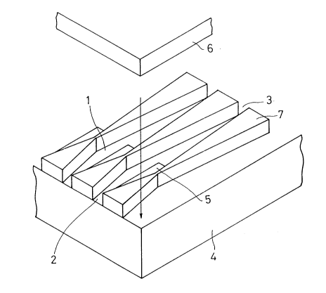
As shown in Figure 1, partition walls 7 are formed on a
~'d~
- 2034298
-- 5
base 4 at regular intervals, and electro-thermal transducer
elements 5 are disposed between adjacent walls. A top plate
6 is attached to provide a liquid jet recording head. The
space defined by the walls, base and the top plate is a
liquid passage 1, the liquid to be ejected out is supplied
from an inlet and is ejected through the ejection outlet 2.
Adjacent the electro-thermal transducer element, the
width of the wall is substantially zero to provide the
maximum width of the passage, although the wall has a small
width for explanation in the Figure.
The dimensions are as follows:
Cross-sectional area of the ejection outlet: 40 x 30
mlcron
Length of the passage: 500 microns
Height of the liquid passage: 400 microns
Size of the electro-thermal transducer element: 32 x
150 micron2
Pitch of passages: 105.8 microns
The maximum width of the passage is 95 microns (electro-
thermal transducer element portion), and the minimum width is30 microns (inlet portion).
Figure 2 is a top plan view of the liquid passage in
this embodiment.
Figure 6 is a top plan view of a conventional passage.
In the conventional passage, the liquid passage is not
converging toward the supply inlet 3. The dimensions of the
conventional passage are the same as those of the embodiment
except that the maximum width is 70 microns (the major
portion of the passage, and that the minimum is 35 microns
(ejection outlet portion).
Operation of the first embodiment will be described in
comparison with the conventional structure. When the
., ~,.
~. ~
2034298
-- 6
electric pulse is applied to the electro-thermal transducer
element, a bubble 8 is produced, as shown in Figure 6, and it
develops. In this embodiment, the width of the passage is
maximum at the portion of the electro-thermal transducer
element, and therefore, the bubble can develop with less
influence of the partition walls, and freely develops into an
oval form. In the comparison example, the maximum passage
width is smaller than that of this embodiment due to the
structure thereof, and therefore, the development of the
bubble is influenced by the walls so that the bubble becomes
much longer than the length of the electro-thermal transducer
element and forms into the shape as shown in Figure 6.
Therefore, the energy of the bubble can be used more
efficiently in this embodiment than in the comparison
example.
During the subsequent liquid supply period, the liquid
flows slowly from the inlet, and therefore, the impedance of
the passage during the liquid supply is smaller than in the
ejection period, but this does not apply to the conventional
passage. The structure of the conventional passage has the
same impedance upon the ejection and during the supply, and
therefore, the properties different depending on whether it
is the ejection period or supply period, cannot be provided.
The impedance has been determined as a compromise. According
to the present invention, the desirable different properties
can be provided.
The description will be made in further detail. The
structure of the liquid passage, more particularly, the size,
position, thermal energy to be produced, passage resistance,
dimension of the ejection outlet and the like, is determined
in consideration of the size of the droplet and the speed of
the droplet. They are not all determined freely because of
the limitations due to the manufacturing process and the
geometrical limitation. If there were no limitation, the
liquid passage would be as short and wide as possible since
then the passage resistance (impedance and inertance) the
.: ,~
_ 7 2034298
efficiency is high, and size and the speed of the droplet
would be determined by the adjustment of the size and
position of the electro-thermal transducer element and the
size of the ejection outlet. Actually, however, there is a
partition wall between adjacent passages in the case of
multi-nozzle arrangement, and therefore, the nozzle width is
limited, and the consideration should be paid to the
mechanical strength of the wall.
The embodiment uses the directivity (direction
dependence) and the flow-dependence of the liquid impedance.
The impedance of the passage is desired to be as small as
possible, as described above. If the impedance is different
between upon the liquid ejection and upon the liquid supply.
Now, the consideration will be made separately for the
inlet side (back side) and outlet side (front side) of the
electro-thermal transducer. Upon the ejection, the liquid is
desirably easily mobile at the front side, and is less mobile
at the back side, that is the impedance is desirably smaller
at the front side and larger at the back side. Upon the
liquid supply period, the liquid retracted into the passage
tends to return, and therefore, the liquid is desirably
easily mobile both at the inlet and the outlet sides, that
is, the impedance is desirably smaller both at the inlet and
outlet side. Therefore, the front impedance is desirably
always small, and the back impedance is desirably large upon
the ejection and small upon the supply. Thus, the back side
impedance is desired to be different.
The present invention has been made in consideration of
the width. The relation between the width and the impedance
is that the impedance decreases with increase of the width.
Upon the ejection of the recording liquid, the width of the
front side is desired to be large, and the width of the back
side is desired to be small, but during the liquid supply
period, the width at the back side is desired to be large.
So, different and contradicting properties are desired. This
- 8 - 2034298
is difficult to solve, but the inventors have found a
solution in consideration of the difference of the liquid
movement upon the ejection and during the supply period.
More particularly, the inventors have particularly noted
the difference between the length of the time period required
for the ejection and the length of the time period required
for the liquid supply. The ejection is effected in a short
period of time, and therefore, the liquid movement speed is
high, but the supply is effected in a long period, and
therefore, the speed of the liquid flow is low. It has been
found that by considering the flow rate difference and the
passage structure, the impedance can acquire the directivity
and the speed-dependency.
The description will first be made as to the back side
of the passage. According to the present invention, the
liquid, upon the ejection, tends to flow at a high speed
through a passage converging from the electro-thermal
transducer to the supply inlet, and therefore, it does not
easily flow. In other words, the impedance is larger than
when the width is constant, and therefore, the ejection is
efficient. During the supply, the liquid flows in the
opposite direction at a low speed through the passage
diverging from the inlet side to the electro-thermal
transducer, and therefore, the impedance is smaller, so that
the liquid supply is effected smoothly.
The front side will be described. In the front side the
flow of the liquid is toward the outlet, that is, from the
electro-thermal transducer to the ejection outlet upon the
ejection and the supply. Therefore, the passage is desirably
diverging toward the ejection outlet, in order to increase
the efficiency.
From the above, it results that the passage is diverging
from the inlet to the outlet. However, the front side of the
passage has to take the role for controlling the size of the
- 9 - 2034298
droplet and the control of the droplet speed. Therefore, the
structure cannot be determined only from the standpoint of
the efficiency.
In addition, the simple diverging structure does not
meet the demand for the increased nozzle density. Then, the
passage structure of the present invention is achieved.
Because of the structure of the present invention, the
desired size and speed of the droplet can be provided, and
the multi-nozzle structure at high density is achieved.
According to the present invention, the back side
structure diverging toward the electro-thermal transducer
permits the maximum passage width as close as possible to the
pitch of the nozzle arrangement at the position where the
electro-thermal transducer element is disposed, so that the
passage impedance of the entire passage can be reduced. The
length of that portion of the passage where the width is
maximum is made extremely small, and the passage width
monotonously reduces both toward the inlet and the outlet,
whereby the insufficient mechanical strength resulting from
the insufficient thickness of the wall between adjacent
passages, can be avoided. In addition, the possible
influence from the pressure produced in the adjacent nozzle
can be avoided. The length in which the width is maximum is
determined is determined on the basis of the property of the
material constituting the passage, the degree of converging
to the inlet and the outlet and the like. The largest
maximum width can be provided when the length is zero, that
is, when the maximum width appear only at a point. The
nozzle structure is particularly effective when plural
nozzles are used, particularly at a high density. In
addition, the distances from the electro-thermal transducer
and the side walls are large, so that the bubble is not
limited by the side walls, and therefore, it can develop
freely, by which the energy conversion efficiency to the
ejection energy can be increased.
A~'
- 10 - 20342q8
As will be understood from Figures 1 and 2, the degree
of converging from the electro-thermal transducer toward the
ejection outlet is higher than that toward the supply inlet.
In other words, the taper of the wall constituting the width
of the passage is steeper at the front side than at the back
side. By doing so, the maximum width position can be closer
to the ejection outlet, and the width of the electro-thermal
transducer element is increased, and in addition, the passage
is shortened.
The reason why the electro-thermal transducer eIement
can be made closer to the ejection outlet, is that the bubble
can develop freely so that the bubble does not expand in the
direction of the liquid flow. In the conventional structure,
if the electro-thermal transducer element is too close to the
ejection outlet, the bubble communicates with the external
air with the result of improper ejection. According to the
present invention the liability is removed. In addition,
since the electro-thermal transducer element is close to the
ejection outlet, the ejection can be effected with a small
electro-thermal transducer element, and therefore, the
efficiency is improved, and the energy consumption can be
reduced. Since the length is reduced the impedance of the
entire passage can be reduced.
Embodiment 2
The liquid jet recording head of the second embodiment
is the same as the first embodiment except that the length of
the passage is 200 microns and that the size of the electro-
thermal transducer element is 45 x 35 micron2. This
embodiment uses most the advantages of the large width of the
passages. The maximum width position is further closer to
the ejection outlet, and the width of the electro-thermal
transducer element is increased, and in addition, the passage
is shortened.
As described in the foregoing, the reason why the
electro-thermal transducer element is made closer to the
-
- 11 2034298
ejection outlet, is that the bubble can develop freely so
that the bubble does not expand in the direction of the
liquid flow. In the conventional structure, if the electro-
thermal transducer element is too close to the ejection
outlet, the bubble communicates with the external air with
the result of improper ejection. According to the present
invention the liability is removed. In addition, since the
electro-thermal transducer element is close to the ejection
outlet, the ejection can be effected with a small electro-
thermal transducer element, and therefore, the efficiency isimproved, and the energy consumption can be reduced. Since
the length is reduced, the impedance of the entire passage
can be reduced.
Embodiment 3
As shown in Figure 4, the electro-thermal transducer
elements 5 are disposed at regular intervals on the base 4
(some parts are omitted for the sake of simplicity in this
Figure). The top plate 6 has grooves at the positions
corresponding to the electro-thermal transducer elements 5 to
establish the liquid passages. The top plate 6 is attached
to the base to form a liquid jet recording head. The
adjacent passages are separated from each other by the
partition wall 7. The liquid to be ejected is supplied from
the supply inlet 3 and is ejected out through the outlet 2.
Adjacent the electro-thermal transducer element, the width of
the partition wall is substantially zero (in the Figure, the
it has a small width for explanation) to provide the maximum
width of the passage. In addition, the height of the passage
is made maximum to provide the maximum cross-sectional area
of the passage.
The dimensions of the passage are the same as those of
the first embodiment with the exception that the cross-
sectional area of the ejection outlet is 35 x 35 micro2 and
that the maximum height of the passage is 60 microns. Figure
5(a) is a top plan view of the passage according to this
embodiment, and Figures 5(b) and 5(c) are a-a' and b-b'
,;~'~
`- 2034298
- 12 -
sectional views, respectively. As will be understood from
Figure 5(c), the top wall of the passage is tapered in the
similar manner as the side walls described in the foregoing.
The same advantageous effects are provided.
TABLE 1
Ejection Ejection Refilling
volume speed time
(10-9cc) (m/s) (micro-sec)
Embodiment 1 126 11 282
Embodiment 2 130 14 222
Embodiment 3 136 13 250
Comparison 81 8.5 316
Table 1 shows the properties of the recording head
according to Embodiments 1, 2, 3 and comparison example. As
will be understood, the recording head according to the
embodiments is advantageous.
According to the present invention, the efficiency of
use of the bubble energy for the ejection is improved, and
the high density arrangement of the nozzles is possible. the
width of the passage can be used to the maximum extent, so
that the efficiency is further improved. The energy
consumption can be reduced. The ejection speed is the same
or higher than that of the conventional structure.
~,
,,~