Note: Descriptions are shown in the official language in which they were submitted.
~;3'~3~
VEHICLE COLLISION REPAIR SUPPORT RACK
This invention relates to a rack up on to which
a vehicle may be moved and ~rom which the vehicle may be
stationaril~ supported ~or frame, sub~frame and bod~
panel straightening and aLigning purposes. The rack
de~ines an outer periphery within the boundaries o~ which
an associated vehicle upon which straightening and
aligning work is to be per~ormed may be supported and the
outer periphery of the frame includes work platforms
supported therefrom ~or guided movement thereabout and
from whish pivotal pull towers are supported, which pull
towers are basically constructed in the manner disclosed
in U.S. Patent No. 4,712,417, but each are modified to
include a vehicle lifting arm. Further, the rack is
vertically adjustable whils maintaining a horizontal
attitude and lock structure is provided for maintaining
the rack in selected vertically adjusted positions.
Also, the rack is provided with folda~ly retractable
vehicle stands.
Various different forms of support racks
including some of the general structural and operational
features o~ the instant invention are disclosed in U.S.
Patent Nos. 4,313,3~5, 4,370,882, 4,398,410, 4,643,015,
~,700,559 and 4,794,783. In addition, pull towers are
not only disclosed in the above menti~ned U.S. Patent No~
4,712~417 but also in U.S. Patent Nos. 4 t 475,716 and
4,658,627. However, these previously know devices do not
include vehicle li~t arm e~uipped pull towers, foldably
retractable vehicle stands or racks which may be
vertically adjusted and a locked in selected vertically
adjusted positions.
13~2
The vehicle repair support rack of the instant
invention has been designed to facilitate the application
of frame, sub-frame and/or body panel pulls on a vehicle
being repaired. The support rack incorporates ~eatur~s
which facilitate the application o~ such repair pulls
throughout the entire repair process, including the
loading of a vehicle on the repair rack, elevation of the
vehicle relative to the rack, stationery anchoriny o~ the
vehicle in an elevated position relative to the ra~k and
the placement of one or more pull towers about the
vehicle on the repair rack as well as adjustment of the
pull tower or towers relative to the vehicle in order to
exert angle pulls thereon, if desired. Further, the
support rack includes foldably retxactable vehicle
stands, vehicle lift arm equipped pull towers and pull
tower supporting carriages which must be positively
locked in adjusted positions rather than reliance upon
friction contact between the support rack and carriages
during a pull.
The main object of this is to provide a vehicle
repair rack upon which a vehicle to be repaired may be
loaded, elevated relative to the rack, sta~ionarily
anchored in elevated pvsition relative to the rack and
have various angle pulls exerted thereon through the
utilization of pull towers.
Another very important object of this invention
is to provide a repair rack with which body component
alignment gages may be readily usedn
Still another ob~ect of this invention is to
provide a vehicle support rack provided with pull towers
moveable thereabout and wherein the pull towers each
include structure for exerting a generally horizontal
.3~L3'~
pull and may have a vehicle lift arm aclded thereto
whereby each pull tower also may be used to elevate a
vehicle relative to the repair rack.
A further object of this invention is to provide
a vehicle repair rack of the type including carriages
moveable thereabout for support of pull towars therefrom
and whereby the carriages include positive lock structure
for locking the carriages in predetermined selected
positions about the rack and also structure which
positively precludes the use of frictional contact
between the rack and pull tower supporting carriages for
maintaining the carriagss stationery relative to the rack
while horizontal pulls or being exerted.
Yet another object of this invention is to
provide a vehicle support rack including vehicle stands
which are foldably retractable.
Still another object of this invention, in
accordance with the immediately preceding object, is to
provide vehicle stands which are also readily removably
supported from the support rack.
Another object of this is to provide a support
rack which is adjustable in height relative to a
supporting ~loor surface and which may be locked in a
plurality of horizontal height adjusted pos~itions
relative to the floor surface.
A final object of this invention to be
specifically enumerated herein is to provide a repair
rack in accordance with the preceding objects and which
will conform to conventional forms of manufacture, be of
simple construction and easy to use so as to provide a
device that will be economically feasible, long-lasting
and relatively trouble free in operation.
:Z~3~
'rhese together with other objects and advantages
which will become subsequently apparent reside in the
details of construction and operation as more fully
hereinafter described and claimed, reference being had to
the accompanying drawings ~orming a part hereo~, where.in
like numerals refer to like parts throughout.
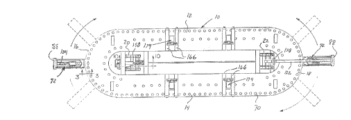
Figure 1 is a top plan view of the repair rack
of the instant invention illustrating a pair of pull
tower support carriages supported therefrom for movement
about the outer periphery of the track and with foldably
retractable vehicle support stands supported from the
rack and one of the pull towers equipped with a vehicle
lifting arm;
Figure 2 is a side elevational view of the
assemblage illustrated in Figure 1;
Figure 3 is an enlarged fragmentary vertical
sectional view taken substantially upon the plane
indicated by the section line 3--3 of Figure 1 and
illustrating the manner in which one of the pull tower
carriages is movably supported from the repair rack and
equipped with rollers to prevent frictional contact
between the carriage and rack during a pull exerted by a
pull tower mounted ~rom the carriage;
Figure 4 is an enlarged perspective view of one
of the pull towers in readiness to exert a generally
hori~ontal pull on a vehicle supported from the rack;
Figure 5 is another enlarged perspective view of
a pull tower with the pull tower embodying a vehicle lift
arm whereby a vehicle supported from the rack may be
elevated in position rPlative to the racX;
Figure 6 is an enlarged ~ragmentary vertical
sectional view taken substantially upon the plane
lL31~
indicated by the section 6-- 6 of Figure 4;
Figure 7 is an enlarged side elevat:ional view oP
one of the pull tower supporting carriages;
Figure 8 is an enlarged perspective view of one
of the ~oldably retractable vshicle stands supported from
the rack;
Figure 3 is an enlarged vertical sectional view
taken substantially upon the plane indicated by the
section line 9--9 of Figure 2;
Figure 10 is an enlarged fragmentary vertical
sectional view taken substantially upon the plane
indicated hy the section line 10-10 of Figure 1 and
illustrating a portion of the jack structure by which the
rack may be elevated in selected positions relative to a
supporting floor surface;
Figure 11 is an enlarged fragmentary vertical
sectional view taken substantia].ly upon the plane
indicated by the section line 11~-11 of Figure 3; and
Figure 12 is a fragmentary, enlarged perspective
vi~w of an upper portion of one of the pull towers
illustrating a hydraulic cylinder powered pull arm
pivotally supported therefrom.
Referring now more specifically to the dxawings
the numeral 10 generally designates the vehicle collision
repair rack of the instant invention. The rack 10
comprises a structure which is ovate in plan shape
including a pair of longitudinally straight opposite side
portions 12 and 14 whose corresponding ends are
interconnected by front and rear semi-circular portions
16 and 18. The rack 10 is supported in elevated position
from a suitable ~100ring 20 through the utilization of
pivoted, parallel front and rear legs 20 and 22 and
z~
includes vertically short depending ~ront and rear feet
24 ancl 25 for stationarily supporting the rack 10 ~rom
the flooring 20 in a lowered position relative thereto.
When the rack 10 is disposed at its lowermost
position supported from the feQt 24 and 26, suitable ramp
structure (not shown~ may be aligned and mated with the
front peripheral portion 16 in order to enable a vehicle
to be driven up onto (or pulled onto3 the ramp 10.
As may be seen from Figure 3 of the drawings,
the ramp 10 includes upper and lower ovate horizontal
plates 30 and 32 vertically registered with each other
and inner and outer edge upstanding ovate plates 34 and
36 extending between and interconnecting the inner and
outer marginal portions, respectively, of the plates 30
and 32. In addition, the lower plate 32 includes a pipe
guide rail 38 supported from the under surface o~ the
inner periphery thexeof and a second pipe guide rail 40
is supported from the upper surface of the outer
periphery thereof.
Two carriages 42 are supported ~rom the rack 10
for movement thereabout. Each carriage 42 includes a
pair of parallel tubular beams 44 and 46 disposed at
generally right angles to the adjacent outer peripheral
portion of the rack 10. ~he beams 44 and 46 extend
beneath the adjacent marginal portion of the rack 10 and
are interconnected at their inner ends by a transverse
plate 48 extending and secured therabetween, the
transverse plate 48 rotably supporting a grooved guide
wheel 50 therefrom rollingly engaged with the underside
of the cylindrical guide rail 38. The outex end portions
of the tubular beams 44 are interconnected by a
transverse plate 52 extending and secured therebetween
~3~2
and an additional pair o~ connecting plate~ 54 and 56
extend between and interconnect the tubular beams 44 and
46 beneath the outer margin of the plate 32 and rotatably
journal a pair of anti-friction rollsrs 57 (see Fiyures
3, 7 and 11) therefrom projecting above the tubular beams
44 and 46 and disposed in closely spaced relation
relative to the underside of the plate 32, the rollers 57
including inner ends which are vertically registered with
the lower margin of the plate 36. Also, a pair of
upstanding buttress plates 58 are supported from the
beams 44 and 46 and mount an upstanding plate 60
therebetween from which a pair of aligned, grooved
rollers 62 corresponding to the rol:Ler 50 are journal~d.
The lower peripheral portions o~ the rollers 62 are
rollingly engaged with the upper cylindrical pipe guide
rail 40 mounted from the upper surface of the outer
periphery o~ the plate 32. Still further, the upstan~ing
plate 60 mounts an inverted L-shaped bracket 64 therefrom
including an apertured upper horizontal flange 66 and a
lock pin 68 is downwardly receivable through a selected
aperture 70 o~ those apertures 70 formed in and spaced
along the outer periphery o~ the upper plate 30 and
passes through the aperture in the upper horizontal
~lange 66, whereby the carriage 42 may be locked in
selected position about the rack 10.
The outer end of each carriage 42 supports a
pull tower referred to in general by the reference
numeral 72 therefrom and each pull tower 72 comprises an
L-shaped structure including a horizontal leg 74 and a
vertical leg 76, a pair of inclined braces 78 being
secured between thP end of the horizontal leg 74 remote
from the vertical leg 76 and an intermediate height
~3~:~fl3~
portion of the vertical leg 76. ~n addition the
longitudinal mid~portion o~ the horizontal leg 74
includes a depending pivot pin 80 which is removably
downwardly, rotably received throuyh a guide sleeve 82
supported ~rom the associated carriage 42. The pivot pin
extends downwardly below the corresponding guide
sleeve 82 and has a retaining sleeve 84 equipped with a
set screw (not shown) mounted on the lower end thereo~ to
releasably prevent upward withdrawal of the pivot pin 80
from the guide sleeve 82. Also, the innermost end o~
each carriage 42 includes an inverted L-shaped bracket 86
constituting a sa~ety bracket for maintaining the
associated carriage 42 on the rac]c lO and the outer end
of the carriage 42 includ~s a second inverted L-shaped
bracket 88 engagable over the outer end extended flange
90 of the corresponding pull tower 72, see Figures 1, 2,
4, 5 and 7, the brackets 86 and 88 being removably
secured to the inner and outer ends of the carriage 42
by any suitable form of removable fastaners (not sh~wn).
Each vertical leg 76 includes a pair of uprights
92 having horizontally registered and vertically spaced
pairs of transvers~ bores 94 formed therethrough. Also,
a notched end plate 96 is mounted upon the free end of
the horizontal leg 74 and includes a chain anchoring
notch 98 formed therein. Further, the horizontal leg 74
includ~s a longitudinal guide 100 upon which a slide 102
is mounted for guided movement ther~along and one end of
a double acting hydraulic cylinder 104 is anchored to the
slide 102 as at 105 while the other end of the hydraulic
cylinder 104 is anchored to the lower end of the vertical
leg 76. The slide 102 includes a chain anchoring opening
106 through which a length of chain 108 passes and the
q~O3~~L3~2
chain 108 also passes through the notch 98. In addition,
the chain 108 passes about a pulley 110 journaled from a
vertically adjustable pin 112 secured through t~e lower
pair of bores 94 and also over a pulley 114 journaled
from a vertically adjustable pin 116 removably secured
through an upper pair of the bores 94. ~he end of khe
chain 108 remote from the notch 98 may be anchored
relative to any portion of an associated vehicle (not
shown) supported from the rack 10 and upon which a pull
is to be exerted~ By engagement of the chain 108 in the
chain anchoring opening 106 and extension of the
hydraulic cylinder 104, a pull will be exerted on the
upper end of the chain 108 and the portion of the
associated vehicle to which the upper end of the chain is
lS attached. If a pull of an extent greater than the
maximum stroke of the hydraulic cylinder is desired,
after the first extension o~ the hydraulic cylinder 104,
the chain 108 is anchored at the notch 98 and released ak
the opening 106. Then, the hydraulic cylinder 104 is
retracted and the chain is subsequently again anchored at
the opening 106. Then, during the next extension o~ the
hydraulic cylinder 104, a further pull on the upper end
of the chain 108 may be e~P-rted.
With attention now invited more specifically to
Figure 5, it may be seen that a third pivot pin 120 has
been secured through the pair of bores 94 spaced
immediately above the pivot pin 112 and that the pivot
pin 120 pivotally mounts the base end of a lift arm 122
having a mid-length chain anchor 124 thereon to which the
upper end of the chain 108 is anchored. The outer or
free end of the lift arm 122 has a slide 126 slidably
mounted thereon and releasably securable in adjusted
i 3 ~ 3 ~L ~d
1.0
positions therealong. The slide 126 pivotally supports
a pinch weld receiving slot 128 therefrom for engagement
w.ith the pinch weld area of a uni-body construction~ The
pinch weld receiving slot 128 may be of any suitable
type.
Also, with attention now invited more
specifically to Figure 12, in lieu of the upper pivot pin
116 and the pulley 114, a hydraulic cylinder powered pull
arm 130 operationally similar to the pull arm disclosed
in U.S. Patent No. 4,712,417 may be pivotally supported
~rom the upper end of the vertical leg 76 through the
utilization of a pivot pin 132 corresponding to the pivot
pin 116.
With attention now invited more specifically to
Figures 2 and 10, the leg 20 is pivotally supported from
the rack lo as at 136 and has floor engagable rollers 138
journaled from its lower end. In addition, an elongated
~onnecting rod 140 is pivotally anchored at its ~orward
end to the lower end of the leg 2() as at 142 and to the
lower end of the rear leg 22 as at 144, whereby the legs
20 and 22 are interconnected for simultaneous and equal
angular displacement relative to the rack lo. T~le lower
end of the leg 22 is equipped with rollers 146
corresponding to the rollers 138, but the roll~rs 146 are
seated in a transverse channel 148 secured to the
~looring 120 whereby the rack 10 is stationarily
supported from the flooring 20 against shifting movement
relative thereto.
~ remotely operable hydraulic cylinder 150 is
operably connected between the rack 10 and an
intermediate length portion of the leg 20 for forcibly
angularly displacing the leg 20 relative to the rack and
R~~L~..
an elon~atecl safety prop 152 is pivotally supported from
the rack 10 as at 154 and includes an angle member 156 on
its free end selectively engagable with points 158, 160
and 162 (see Figure 10) in order to positively define
selected elevated positions of the rack 10 above the
lowermost position thereof with its feet 24 and 26
engaged with the flooring 20.
With attention now invited more speci~ically to
Figures 1, 8 and 9, longitudinally spaced portions of
each of the side portions 12 and 14 o~ the rack 10
include pairs of transverse guideways 166 supported
therefrom each including a plurality o~ components
secured together by suitable fasteners 168. Each pair
o~ guideways 166 define a guid~way area 170 in which to
shiftably receive a corresponding base plate 172 from the
outer margin of the corresponding sid~ portion of the
rack 10. Each base plate 172 comprises the base of a
vehicle support stand referred to in general by the
re~erence numeral 174. Each st:and 174 includes an
upright plate 176 pivotally supported from the base plate
172 as at 178 and supporting a pair of axially spaced
apart and horizontally aligned hinge barrels 180 on the
outer surface of an upper end portion thereof. In
addition, each stand 174 further includes an inclined
plate 1~2 pivotally supported from the correspondi~g base
plate 172 at 184 and equipped with a single hinge barrel
186 on its upper end received between and axially aligned
with the hinge barrels 180, a removable hinge or latch
pin 188 being passed through the barrels 180 and 186 in
order to lock the upright plate 176 in an upright
position. The upper end o~ the upright plate 176
includes pinch weld area clamps 190 which may be
removably clamp engaged with pinch weld areas of a uni-
body construction vehicla. When the pin 188 is removed,
the upskanding plate 176 as well as the inclined plate
182 may be inwardly and downwardly swung toward collapsed
positions thereof closely overlying the upper plate 30
and the base plate 172, respectively.
In operation, the rack 10 is first lowered to
the lowest position thereof with the feet 24 and 26
engaged with and supported from the flooring 20. Then,
a vehicle to be worked upon is loaded onto the rack 10
from the forward end portion 16 thereo~. Thereafter, the
pull towers 72 are equipped with the lift arms 122 and
positioned at one side of the vehicle at points spaced
longitudinally therealong, the carriages 42 being locked
into the desired positions thereof by the pins 68. The
hydraulic cylinders 104 are utilized to upwardly swing
the outer ends of the lift arms 122 to elevate the pinch
weld clamps 128 into positions closely beneath
longitudinally spaced portions of the associated pinch
weld area of the vehicle disposed on the rack 10. The
pinch weld clamps 128 are then clamped to the near pinch
weld areas while manual pressure is applied to the outer
~nds of the lift arms 122 in order to elevate the same
sufficiently to enable the pinch weld clamps 128 to be
clamp engaged with the pinch weld areas and the hydraulic
cylinders 104 are then further actuated to lift the
adjacent side of the vehicle. Thereafter, the vehicle
support stands 174 are swung upwardly from their
downwardly retracted positions and locked in the
upstanding positions thereof through utilization of the
pins 88.
L3~
The fasteners 168 do not secure the guideways
166 to the upper plate 30, but brackets 192 and 194
removably and fixedly secured, respectively, at opposite
ends of tha guideways 166 support the guideways 166 ~rom
the upper plate 14 for shifting movement therealong into
the desired positions. Thereafter, the pinch weld clamps
190 are opened and the vehicle is lowered by the
hydraulic cylinders 104 as the base plates 172 are
ad~usted in position along the guideways 166. Then, the
pinch weld clamps are engaged with the adjacent pinch
weld areas of the associated vehicle and the pinch weld
clamps 128 may be released and the lift arms 122 may be
lowered. Thereafter, the carriages 42 are moved around
the rack lO to the opposite side of the vehicle and the
lift arms 122 are utilized to lift other side of the
vehicle Eor the purpose of engaging the pinch weld clamps
190 of the opposite side vehicle suppoxt stands 174 with
the pinch weld areas on that side o:~ the vehicle. After
the four vehicle support stands 174 have been engaged
with the pinch weld areas of the vehicle on opposite
sides thereof, the set screws 196 carried by the
guideways 166 may be tightened to maintain the base
plates 172 in adjusted positions relative to the
guideways 166 and the upper plate 30, the set screws 196
bearing down up on the plates 172 and forcing the latter
down into tight clamped engagement with the upper plate
30.
Thereafter, the necessary pulls may be exerted
on the body of the vehi.cle either through the utilization
of the chain 108 in the manner illustrated in Figure ~ or
through the utili~ation o~ a second chain (not shown)
operatively associated with the pull arm 130 illustrated
f~3~2~
14
in Figure 12, the pull arm 130 being adjustably
positionable alvng the vertical leg 76 o~ the pull tow~r
7~. Further, while pu]ls are being applied on the body
of a vehicle anchored relative to the rack 10, the tow~r
72 tilts inwardly at its upper end and the carriage 42 is
similarly titlted, thus contactiny the upper peripheral
portions of rollers 57 with the opposing undersurface
portion of plate 32. The rollers 57 are provided to
enable free shifting of the carriage 42 while the latter
is tilted and to thereby require the use o~ the pin 68 to
lock the carriage in adjusted positions, rather than
relying upon undependable frictional engagement between
the rack 10 and the carriage 42 at the area o~ the roller
57, were the latter not provided.
The Eoregoing is considered as illustrative only
of the principles of the invention. Further, since
numerous modifications and changes will readily occur to
those skilled in the art, it is not desired to limit the
invention to the exact constructic)n and operation shown
and described, and accordingly, all suitable
modifications and e~uivalents may be resorted to, falling
within the scope of the invention.