Note: Descriptions are shown in the official language in which they were submitted.
~` 2034371
-1- 13DV-9820
AUXILIARY REFRIGERATED AIR SYSTEM EMPLOYING
MIXTURE OF AIR BLED FROM TURBINE ENGINE COMPRESSOR
AND AIR RECI~CULATED WITHIN AUXILIARY SYSTEM
CROSS-REFERENCE TO RELATED APPLICATION
Reference is hereby made to the following copending
U. S. patent application dealing with related subject
matter and assigned to the assignee of the present
invention: "Auxiliary Refrigerated Air System
Employing Input Air From Turbine Engine Compressor
After Bypassing And Conditioning Within Auxiliary
System" by S. W. Renninger et al, assigned U. S.
Serial No. and filed (13DV-10273)
BACKGROUND OF THE INVENTION
F~eld of the Invention
The present invention relates generally to gas
turbine engines and, more particularly, to an auxiliary
refrigerated air system on an aircraft employing input
air, from a suitable source such as air bled from the
turbine engine compressor, and air recirculated within
the system.
. . .. , . -
. . .
: :. , .
`` 2034371
-2- 13DV-9820
~escriDtion of the Prior Art
The requirement has existed heretofore for aircraft
turbine engine systems to produce cool air for use in
aircraft support systems such as for cabin
environmental control and avionic cooling. In one
conventional aircraft support system, fresh air is
initially obtained by bleeding air from one or more of
the aircraft's engines and then conditioned before
introduction into the pressurized fuselage of the
aircraft. In this support system as described and
illustrated in U. S. Pat. No. 4,262,495 to Gupta et al,
the bleed air is conditioned by the coordinated
operation of a power turbine, a recirculation air
compressor, an air filter and an air-to-air heat
exchanger of the system. Another known aircraft
support system utilizing engine bleed air to heat the
engine fuel is described and illustrated in U. S. Pat.
No. 4,404,793 to Coffinberry.
The air quantity and air temperature requirements
of conventional aircraft support systems have been
relatively modest heretofore. The cooling requirements
of future turbine engine systems will likely demand
significantly increased quantities of air at
substantially lower temperatures. One such example is
in the area of superconductors. Emerging
superconductor technology may find application in
future turbine engine systems for power generation, as
one example, or in magnetic bearings, as a second
example. Although the technology of superconductors
has made major advances in elevating the temperature at
which they function, a cold or refrigerated temperature
by normal standards is still required.
Conventional cold or refrigerated air systems used
on aircraft heretofore do not provide air in sufficient
quantities and at sufficiently low temperatures to meet
the anticipated cooling requirements of future turbine
.. . . .
. .: . .
-, . ... -, :: - :~ :
2~3~37~
-3- 13DV-9820
engine systems. Consequently, a need exists for a
refrigerated air system which will meet forecasted
future requiremçnts.
SUMMARY OF THE INVENTION
The present invention provides an auxiliary
refrigerated air system which satisfies the
aforementioned needs. The auxiliary system of the
present invention combines currently-available turbine
engine technologies with a mixture of air, from a
suitable source such as air bled from a turbine engine
compressor, and air recirculated within the system to
produce cold or refrigerated air at sufficiently
reduced temperature and in sufficient quantities to
satisfy future requirements. For purpose of brevity,
as used in the description and claims hereinafter the
term "air" is meant to include any other materials in
fluid and/or gaseous form besides atmospheric air. By
employing the auxiliary system of the present
invention, bleed air from the engine at compressor
discharge conditions, having a typical temperature of
1150F, can be reduced to a temperature well below
freezing without completely exhausting the pressure
potential of the bleed air exiting the auxiliary
system.
Accordingly, the present invention is directed to
an auxiliary refrigerated air system, such as
associated with an aircraft turbine engine. The
auxil$ary system comprises: (a) first and second
tandemly-arranged auxiliary turbine components; (b) an
air mixing valve; (c) an air dividing valve; (d) an air
recirculation loop; (e) an auxiliary air compressor;
and (f) a heat exchanger. Each of the first and second
turbine components has respective entrance and exit
sides and is operable for receiving air at the entrance
sides and producing energy-depleted air at the exit
,'.~' ' ' -,` . : '.................. ' ' '
;::. . . . .: : . -
:: . - . . . . .
203~371
-4- 13DV-9820
sides. The air mixing val-~e is connectable to a source
of input air for receiving and mixing input air with
dilution air and producing an air mixture. The air
dividing valve is connected in communication between
the exit side of the first auxi~iary turbine component
and the entrance side of the second auxiliary turbine
component for diverting a portion of the energy-
depleted air exiting from the first auxiliary turbine
component. The air recirculation loop is connected in
communication between the mixing valve and the dividing
valve for recirculating to the mixing valve the portion
of the air diverted by the dividing valve from the exit
side of the first auxiliary turbine component to
provide the dilution air to the mixing valve.
The auxiliary air compressor of the system has
inlet and outlet sides. The auxiliary compressor is
drivingly connected to the first and second auxiliary
turbine components and connected in communication at
the inlet side with the mixing valve. The auxiliary
compressor further is operable for receiving the air
mixture at the inlet side from the mixing valve and
producing compressed air at the outlet side upon
operation of the first and second auxiliary turbine
components. The heat exchanger has a first side and a
second side. The heat exchanger at its first side is
connectable in communication with a flow of fluid, such
as aircraft engine fuel, which provides a heat sink.
The heat exchanqer at its second side is connected in
communication between the outlet side of the auxiliary
air compressor for receiving compressed air therefrom
and the entrance side of the first auxiliary turbine
component for discharging conditioned air thereto. The
auxiliary system also includes a common drive shaft
which drivingly interconnects the auxiliary air
compressor with the first and second auxiliary turbine
components for causinq operation of the auxiliary
compressor upon operation of the auxiliary turbine
, .. - .
!
'', ', ' , ~ ', '' ~ ' ' ~ ' ' ' ' "
- 203~
-5- 13D~-9820
components.
These and other features and advantages and
attainments of the present invention will become
apparent to those skilled in the art upon a reading of
the following detailed description when taken in
conjunction with the drawings wherein there is shown
and described an illustrative embodiment of the
invention.
BRIEF DESCRIPTION OF T~E DRAWINGS
In the course of the following detailed
description, reference will be made to the attached
drawings in which:
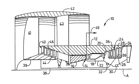
Fig. 1 is a schematic view of a gas turbine engine.
Fig. 2 is a schematic view of an auxiliary cold air
production system in accordance with the present
invention.
DETAILE~ DESCRIPTION OF THE INVENTION
In the following description, like reference
characters designate like or corresponding parts
throughout the several views. Also in the following
description, it is to be understood that such terms as
"forward", "rearward", "left", "right", "upwardly",
"downwardly", and the like, are words of convenience
and are not to be construed as limiting terms.
In General
Referring now to the drawings, and particularly to
Fiq. 1, there is illustrated a gas turbine engine,
generally designated 10, to which the present invention
can be applied. The engine 10 has a longitudinal
center line or axis A and an annular casing 12 disposed
coaxially and concentrically about the axis A. The
. . , - ~- ..
.: .. . . .
203~371
-6- 13DV-9820
engine 10 includes a core gas generator engine 14 which
is composed of a compressor 16, a combustor 18, and a
high pressure turbine 20, either single or multiple
stage, all arranged coaxially about the longitudinal
axis or center line A of the engine 10 in a serial,
axial flow relationship. An annular drive shaft 22
fixedly interconnects the compressor 16 and high
pressure turbine 20.
The core engine 14 is effective for generating
combustion gases. Pressurized air from the compressor
16 is mixed with fuel in the combustor 18 and ignited,
thereby generating combustion gases. Some work is
extracted from these gases by the high pressure turbine
20 which drives the compressor 16. The remainder of
the combustion gases are discharged from the core
engine 14 into a low pressure power turbine 24.
The low pressure turbine 24 includes an annular
drum rotor 26 and a stator 28. The rotor 26 is
rotatably mounted by suitable bearings 30 and includes
a plurality of turbine blade rows 34 extending radially
outwardly therefrom and axially spaced. The stator 28
is disposed radially outwardly of the rotor 26 and has
a plurality of stator vane rows 36 fixedly attached to
and extending radially inwardly from the stationary
casing 12. The stator vane rows 36 are axially spaced
so as to alternate with the turbine blade rows 34. The
rotor 26 is fixedly attached to drive shaft 38 and
interconnected to drive shaft 22 via differential
bearings 32. The drive shaft 38, in turn, rotatably
drives a forward booster rotor 39 which forms part of a
booster compressor 40 and which also supports forward
fan blade rows 41 that are housed within a nacelle 42
supported about the stationary casing 12 by a plurality
of struts 43, only one of which is shown. The booster
compressor 40 is comprised of a plurality of booster
blade rows 44 fixedly attached to and extending
radially outwardly from the booster rotor 39 for
:r" ~
-: . . , :. ,' ,, .:~ . ', : : :
... . .
2~3~371
-7- 13DV-9820
rotation therewith and a plurality of booster stator
vane rows 46 fixedly attached to and extending radially
inwardly from the stationary casing 12. Both the
booster blade rows 44 and the stator vane rows 46 are
axially spaced and so arranged to alternate with one
another
Auxiliary Refriaerated Air Svstem of the Invention
Referring to Fig. 2, there is illustrated
schematically an auxiliary refrigerated air system,
generally designated 48, constructed in accordance with
the principles of the present invention. The auxiliary
system 48 utilizes a mixture of input air from a
suitable source, such as air extracted or bled off
preferably from the core engine compressor 16 of the
turbine engine 10 of Fig. 1, and dilution air
recirculated within the auxiliary system 48 to provide
cold or refrigerated air at the desired reduced
temperature and in the desired quantity. Thus, by
employing the auxiliary system 48, air at compressor
discharge conditions which is bled off from the engine
10, via a conduit 49, to the system 48 can be reduced
to a temperature and provided in a quantity to supply
contemplated cooling requirements of the aircraft
support systems.
In its basic components, the auxiliary refrigerated
air system 48 includes first and second tandemly-
arranged auxiliary turbine components 50 and 52, an air
mixing valve 54, an air dividing valve 55, an air
recirculation loop 56, an auxiliary air compressor 58,
and a heat exchanger 60. Each of the first and second
turbine components 50, 52 of the auxiliary system 48
has an entrance side 50A, 52A and an exit side 50B,
52B. Also, each turbine component 50, 52 is operable
in a well-~nown manner for generating power in response
to receiving energy-laden air at its entrance side 50A,
., . -: ,
-` 2~3~37 ~
-8- 13D~-9820
52A and producing energy-depleted air at its exit side
50B, 52~. The auxiliary system 48 also includes a
common drive shaft 62 which drivingly interconnects the
auxiliary compressor 58 with the auxiliary turbine
components 50, 52 for causing operation of the
auxiliary compressor 58 in a well-known manner to
auqment the energy of the air processed by the
compressor upon operation of the auxiliary turbine
components.
The air mixing valve 54 of the auxiliary system 48
is connected to the core engine compressor 16, via the
conduit 49, for receiving and mixing input air bled off
from the core engine compressor 16 with dilution air
from the air recirculation loop 56 to produce an air
mixture to be boosted in energy by the auxiliary air
compressor 58. The air dividing valve 55 is connected
in communication between the exit side 50B of the first
auxiliary turbine component 50 and the entrance side
52A of the second auxiliary turbine component 52 for
diverting a portion of the energy-depleted air exiting
from the first auxiliary turbine component. The air
recirculation loop 56 is connected in communication
between the mixing valve 54 and the dividing valve 55
for recirculating to the mixing valve 54 the portion of
the air diverted by the dividing valve 55 from the exit
side 50B of the first auxiliary turbine component 50 to
provide the dilution air received at the mixing valve
54 for mixing with the input air.
The auxiliary air compressor 58 of the auxiliary
system 48 has an inlet side 58A and an outlet side 58B.
The auxiliary compressor 58 is drivinqly connected to
the first and second auxiliary turbine components 50,
52 by the drive shaft 62 and is connected in
communication at its inlet side 58A with the mixing
valve 54. The auxiliary compressor 58, upon being
driven by the auxiliary turbine components 50, 52,
operates in a well-known manner to receive the air
.. . ..
. ~ . . - . ~ . ,
.:. . .. . .: . :
.. . . . . . . .
--` 2~34371
-9- 13DV-9820
mixture at its inlet side 58A (from t~e mixing valve
54) and produce compressed air at its outlet side 58B.
The heat exchanger 60 of the auxiliary system 48
has a first side 60A and a second side 60B. The heat
exchanger 60 at its first side 60A is connected in
communication with a suitable fluid which provides a
heat sink, for instance, the aircraft engine fuel. By
way of example, the flow path P of the fuel from its
storage tank (not shown) to the turbine engine 10 can
be diverted through the heat exchanger 60. The heat
excXanger 60 at its second side 60B is connected in
communication between the outlet side 58~ of the
auxiliary compressor 58 for receiving compressed air
therefrom and the entrance side 50A of the first
auxiliary turbine component 50 for discharging
conditioned (cooled) air thereto.
In the operation of the auxiliary system 48, bleed
air is extracted from the core engine compressor 16 via
conduit 49 and mixed by the air mixing valve 54 with a
dilution air (which recirculates through the system 48)
from the air recirculation loop 56 and dividing valve
55. The mixing valve 54 provides an air mixture which
is a high pressure source of air at a temperature
significantly reduced from that at which the air is
extracted from the core engine compressor 16. At the
mixing vàlve 54, the pressure of the dilution air is
substantially equal to the pressure of the air
extracted from the core engine compressor 16. In this
manner, the mixed air produced by the mixing valve 54
and inputted to the auxiliary compressor 58 has
substantially the same pressure as the air that is
extracted from the core engine compressor 16.
The air mixture from the mixing valve 54 is passed
through the auxiliary compressor 58 to increase its
pressure and temperature and then passed through the
heat exchanger 60 to lower the mixed air temperature.
If fuel is used to cool the air, the fuel may then be
, .. ~ ~ . . . .
: -,
- 2034371
-10- 13DV-9820
burned in the engine combustion system. Fuel is likely
to be used as the heat sink because it is readily
available on the aircraft to serve this purpose. If
some other suitable liquid happens to be available on
the aircraft, it could be used in place of the fuel for
this purpose.
The cooled mixed air is then passed through the
first auxiliary turbine component 50 with a pressure
drop less than the pressure rise produced by the
auxiliary compressor 58 to compensate for line losses
in the auxiliary system 48. Hence, the exit pressure
of the air at the first auxiliary turbine component 50
is compatible with the pressure of air extracted from
the core engine compressor 16. A temperature drop is
associated with the pressure drop. Then, a quantity of
air, equal to tha~ extracted from the core engine
compressor 16, is passed through the second auxiliary
turbine component 52. The remainder of the air exiting
the fixst auxiliary turbine component 50 is routed by
the air dividing valve 55 to the air recirculation loop
56 to be used as the cold dilution air previously
described.
Energy is extracted by the second auxiliary turbine
component 52 to further reduce the temperature of the
air. The energy removed by the turbine components 50
and 52 may be equal to that required to drive the
auxiliary compressor 58 via the drive shaft 62. If the
energy is equal, no external power input (aside from
the high pressure bleed air) is required to operate the
auxiliary system 48; however, external power could be
supplied or power could be extracted to tailor the
system to a particular need if desired. The ultimate
temperature of the cold or refrigerated air delivered
by the system 48 will depend on the back pressure
behind the second turbine component 52 relative to the
charging pressure and temperature from the source in
the core engine 14. Computer calculations have shown
,.... . .. . .
:., ~ : .. - .. . .. . ;
: . . . . . . . .
.... : - : - -
.: . : , -
~ . .. . . - ~ 1'-`
: .. .. . . .. .
., ... : ~.. , : - .
20~4371
-11- 13DV-9820
that ble~d air from the engine 14 at compressor
discharge conditions, with a typical temperature of
1150 F, can be reduced to a temperature below freezing
using the auxiliary system 48 without completely
exhausting the pressure potential of the bleed air at
the exit side 52B of the second auxiliary turbine
component 52.
The auxiliary system 48 can be provided as a
separate, stand alone unit on an aircraft connected to
the engine compressor 16 only by the conduit 49.
Further, the auxiliary turbine components SO and 52 can
be separate turbine components as shown or separate
stages of a single turbine 64, as seen in dashed
outline in Fig. 2. The dilution air would be extracted
as an inner stage bleed between the stages of the
single turbine 64. The turbine engine compressor is
only one example of a suitable source of input air to
the auxiliary system 48. Other possible sources of
input air are ram air, fan bleed air, etc. Any high
pressure gas source might be used.
It is thought that the present invention and many
of its attendant advantages will be understood from the
foregoing description and it will be apparent that
various changes may be made in the form, construction
and arrangement of the parts thereof without departing
from the spirit and scope of the invention or
sacrificing all of its material advantages, the forms
hereinbefore deseribed being merely preferred or
exemplary embodiments thereof.
:~ . . . .
:. ., , : :, -
, :~.:
,:: , ::
,:: , . . .. . .
.: . ,
.. , . ~ : , .