Language selection

Search

Patent 2034390 Summary

Third-party information liability

Some of the information on this Web page has been provided by external sources. The Government of Canada is not responsible for the accuracy, reliability or currency of the information supplied by external sources. Users wishing to rely upon this information should consult directly with the source of the information. Content provided by external sources is not subject to official languages, privacy and accessibility requirements.

Claims and Abstract availability

Any discrepancies in the text and image of the Claims and Abstract are due to differing posting times. Text of the Claims and Abstract are posted:

  • At the time the application is open to public inspection;
  • At the time of issue of the patent (grant).
(12) Patent Application: (11) CA 2034390
(54) English Title: COMPENSATING FOR POWER OUTAGE IN ELECTRIC ENERGY METER
(54) French Title: DISPOSITIF DE REMISE A L'HEURE JUSTE D'UN KILOWATTHEUREMETRE, A LA SUITE D'UNE PANNE DE COURANT
Status: Dead
Bibliographic Data
(52) Canadian Patent Classification (CPC):
  • 324/70
(51) International Patent Classification (IPC):
  • G01R 22/00 (2006.01)
  • G01R 21/133 (2006.01)
(72) Inventors :
  • BALCH, RICHARD A. (United States of America)
(73) Owners :
  • GENERAL ELECTRIC COMPANY (United States of America)
(71) Applicants :
(74) Agent: CRAIG WILSON AND COMPANY
(74) Associate agent:
(45) Issued:
(22) Filed Date: 1991-01-17
(41) Open to Public Inspection: 1991-10-06
Availability of licence: N/A
(25) Language of filing: English

Patent Cooperation Treaty (PCT): No

(30) Application Priority Data:
Application No. Country/Territory Date
505,203 United States of America 1990-04-05

Abstracts

English Abstract


11-ME-234


ABSTRACT OF INVENTION


A method and apparatus for improving the timekeeping accuracy
of a time of use or demand of energy electronic register in an
electric energy meter includes compensating for the absence of line
frequency timing pulses for the period between the occurrence of a
power outage and the actuation of backup timekeeping resulting from
the power supply filter capacitor discharge time. A timing counter
counts minutes of line frequency timing signals by decrementing a
counter which is also provided with the interval interrupt
operating pulses of the electronic register such that in the
absence of line frequency pulses the interval interrupt operating
pulses are counted and added to electronic register timekeeping
system after a power down mode of operation.


Claims

Note: Claims are shown in the official language in which they were submitted.


11-ME-234


What I claim is:
1. In an electric energy meter including an electronic time
of use or demand of energy register adapted to be connected in
circuit with power lines to meter the energy being consumed at
predetermined times by a load in circuit with the power lines, a
timekeeping system utilizing the power line frequency for
timekeeping purposes, and a power supply energized by the power
lines to provide DC power to electronic circuitry of the electronic
resister and including a capacitor which maintains the DC power
during brief power outages, a method of compensation for line
frequency timing during the time period of the start of a power
outage until the electronic register shifts from power line timing
operation to backup timekeeping operation comprising:
providing a power fail detector circuit which is actuated
when the output voltage from said power supply falls below a
predetermined value;
generating a power fail control signal upon actuation of
said power fail detector circuit;
connecting backup power and backup timekeeping in circuit
with said electronic register in response to said power fail
control signal; and
providing timing compensation for the time period between
the occurrence of a power outage and the generation of a power


17

11-ME-234
fail control signal;
said timing compensation including pulsing a counter with
the basic interval interrupt of said electronic register and
line frequency pulses;
periodically providing the output of said counter to the
timekeeping system of said electronic register, said output
being the line frequency pulses during the presence of line
frequency pulses;
counting the basic interval interrupt pulses which occur
during the period of a power outage until actuation of said
power fail detector circuit without the presence of line
frequency pulses; and
adding time to said timekeeping for said electronic
register based on the basic interval interrupt pulses counted
during said period between a power outage and actuation of
said power fail detector circuit.
2. The method of timekeeping compensation for an electronic
register in an electric energy meter of claim 1 including the
additional step of returning said counter to its initial state upon
each addition of a predetermined time period to said timekeeping
system.
3. The method of timekeeping compensation for an electronic
register in an electric energy meter of claim 2 including the
additional step of providing a frequency factor to relate the
frequency of said basic interval interrupt signal to said line


18

11-ME-23
frequency.
4. The method of timekeeping compensation for an electronic
register in an electric energy meter of claim 3 wherein said
frequency factor is provided by dividing the basic interval
interrupt pulses which are counted by two.
5. The method of timekeeping compensation for an electronic
register in an electric energy meter of claim 4 including the
additional step of providing a correction factor to account for the
difference between the frequency of said basic interval interrupt
signal and said line frequency.
6. The method of timekeeping compensation for an electronic
register in an electric energy meter of claim 5 wherein said basic
interval interrupt signal is in the order of 7.8125 milliseconds,
said line frequency is nominally 60 Hertz, and said correction
factor is an amount adequate to correct for said counter being in
the order of 6.25 percent fast:.
7. The method of timekeeping compensation for an electronic
register in an electric energy meter of claim 1 wherein said power
fail detector includes a biased zener diode to establish said
predetermined value of voltage, and when the output voltage from
said power supply falls below said predetermined value, said power
fail control signal connects a backup oscillator in circuit with
said electronic register to provide said backup timekeeping during
said power outage.
8. The method of timekeeping compensation for an electronic


19

11-ME-234
register in an electric energy meter of claim 7 wherein said backup
power is a battery operatively connected in circuit with said
electronic register in response to said power fail control signal,
and said electronic register maintains a record of the period of
time said battery is operatively connected in circuit with said
electronic register during power outages.
9. The method of timekeeping compensation for an electronic
register in an electric energy meter of claim 8 including the
additional step of displaying said record of the period of time
said battery is operatively connected in circuit with said
electronic register upon presentation of a battery command signal
to said electronic register.
10. The method of timekeeping compensation for an electronic
register in an electric energy meter of claim 1 wherein said power
supply includes a filter capacitor and said filter capacitor is
selected to be of sufficiently large capacitance that said power
supply voltage remains above said predetermined voltage during
momentary power outages.
11. The method of timekeeping compensation for an electronic
register in an electric energy mater of claim 10 wherein said time
compensation is provided for the actuation period of time between
the occurrence of a power outage and the discharge of said filter
capacitor to said predetermined voltage.
12. The method of timekeeping compensation for an electronic
register in an electric energy meter of claim 11 wherein said power


11-ME-234
fail control signal sets the microprocessor of said electronic
register in a power down mode of operation to maintain unread
energy data already in said electronic register, to continue
timekeeping, and to monitor the power line to detect the
restoration of line power.
13. The method of timekeeping compensation for an electronic
register in an electric energy meter of claim 12 including the
additional step of resuming normal operation of said electronic
register and discontinuing said power down mode of operation when
restoration of line power is detected.
14. The method of timekeeping compensation for an electronic
register in an electric energy meter of claim 13 wherein resuming
normal operation of said electronic register includes adding the
time of the power outage and the actuation period to the
timekeeping system of said electronic register.
15. The method of timekeeping compensation for an electronic
register in an electric energy meter of claim 14 wherein the
electronic register activity is discontinued during said power down
mode along with the discontinuance of register displays in response
to register switching action.
15. The method of timekeeping compensation for an electronic
register in an electric energy meter of claim 15 wherein upon
restoration of power on said power lines, the timekeeping functions
of said electronic register are caught up during a catch up period,
and the electronic register output and register displays in


21

11-ME-234
response to register switching action are discontinued during said
catch up period.
17. The method of timekeeping compensation for an electronic
register in an electric energy meter of claim 16 wherein signals
representing energy consumption during said catch up period are
added to the energy consumption being metered.
18. The method of timekeeping compensation for an electronic
register in an electric energy meter of claim 17 wherein said
backup timekeeping during said power down mode of operation is
provided by a crystal oscillator, said crystal oscillator being
connected in circuit with said electronic register upon said
generation of a power fail control signal.
19. In an electric energy meter including an electronic time
of use or demand of energy register adapted to be connected in
circuit with power lines to meter the energy being consumed at
predetermined times by a load in circuit with the power lines, a
timekeeping system utilizing the power line frequency for
timekeeping purposes, and a power supply energized by the power
lines to provide DC power to electronic circuitry of the electronic
register and including a capacitor which maintains the DC power
during brief power outages, a method of providing a power down mode
of operation during a period of power outage on said power lines,
comprising:
generating a power fail signal upon detection of said
power outage by a power fail circuit;


22


11-ME-234
connecting backup timing means and backup power in
circuit with said electronic register in response to said
power fail signal;
setting said electronic register in a power down mode of
operation to conserve said backup power during said power down
mode of operation;
maintaining said timekeeping based on said backup timing
means during said power down mode of operation;
generating a timing signal in response to the time period
between said power outage and the connection of said backup
timing means;
discontinuing at least some of the normal functions of
said electronic register during said power down mode of
operation;
catching up said timekeeping system through use of said
timing signal; and
discontinuing said power down mode of operation and
resuming normal operation of said electronic register upon
resumption of power on said power lines.
20. The method of operating an electronic register in a power
down mode of operation during power outages of claim 19 wherein the
generating of said timing signal includes the use of a timing
counter which counts those operating pulses of said electronic
register which exceed line frequency pulses from said power lines
such that said timing counter effectively only counts timing pulses


23

11-ME-234
in the absence of line frequency pulses.
21. The method of operating an electronic register in a power
down mode of operation during power outages of claim 20 wherein
said timing counter is a decrementing counter which is periodically
zeroed as long as line frequency pulses are provided to offset said
operating pulses.
22. The method of operating an electronic register in a power
down mode of operation during power outages of claim 21 wherein
said operating pulses are the basic interval interrupt period
pulses used to establish the timing periods during a portion of
which the optical system of said electronic register is energized,
and said operating pulses are continued independent of power on
said power lines.
23. The method of operating an electronic register in a power
down mode of operation during power outages of claim 22 wherein
said operating pulses are counted for timekeeping purposes during
the period between failure of line frequency to said timing counter
and the provision of backup timing in response to said power fail
signal.
24. The method of operating an electronic register in a power
down mode of operation during power outages of claim 23 including
the additional step of providing a time factor to more closely
relate said operating pulses to said line frequency.
25. The method of timekeeping compensation for an electronic
register in an electric energy meter of claim 24 wherein said time


24

11-ME-234
factor is provided by dividing the number of operating pulses which
are counted by two to provide substitute line frequency pulses and
utilizing said substitute line frequency pulses as part of said
timekeeping system.
26. The method of timekeeping compensation for an electronic
register in an electric energy meter of claim 254 including the
additional step of providing a correction factor to account for the
asynchronous difference between the frequency of said operating
pulses and said line frequency.
27. The method of timekeeping compensation for an electronic
register in an electric energy meter of claim 26 wherein said
operating pulses are in the order of 7.8125 milliseconds, said line
frequency is nominally 60 Hertz, and said correction factor is an
amount adequate to correct for said counter being in the order of
6.25 percent fast.
28. The method of timekeeping compensation for an electronic
register in an electric energy meter of claim 27 wherein said power
fail detector includes a biased zener diode to establish said
predetermined value of voltage; and when the output voltage from
said power supply falls below said predetermined value, said power
fail control signal connects a backup oscillator in circuit with
said electronic register to provide said backup timekeeping during
said power outage.
29. The method of timekeeping compensation for an electronic
register in an electric energy meter of claim 28 wherein said


11-ME-234
backup power is a battery connected in circuit with said electronic
register in response to said power fail control signal, and said
electronic register maintains a record of the period of time said
battery is connected in circuit with said electronic register
during power outages.
30. The method of timekeeping compensation for an electronic
register in an electric energy meter of claim 29 including the
additional step of displaying said record of the period of time
said battery is connected in circuit with said electronic register
upon presentation of a battery command signal to said electronic
register.
31. The method of operating an electronic register in a power
down mode of operation during power outages of claim 19 wherein
said power supply includes a filter capacitor and said filter
capacitor is selected to be of sufficiently large capacitance that
said power supply voltage remains above said predetermined voltage
during momentary power outages.
32. The method of timekeeping compensation for an electronic
register in an electric energy meter of claim 31 wherein said time
compensation is provided for the period of time between the
occurrence of a power outage and the discharge of said filter
capacitor by power delivered to said electronic register to said
predetermined voltage.
33. The method of timekeeping compensation for an electronic
register in an electric energy meter of claim 32 wherein said power


26

11-ME-234
fail control signal sets the microprocessor of said electronic
register in said power down mode of operation to maintain unread
energy data already in said electronic register, to continue
timekeeping, and to monitor the power line to detect the
restoration of line power.
34. The method of timekeeping compensation for an electronic
register in an electric energy meter of claim 33 including the
additional step of resuming normal operation of said electronic
register from said power down mode of operation when restoration of
line power is detected.
35. The method of timekeeping compensation for an electronic
register in an electric energy meter of claim 34 wherein resuming
normal operation of said electronic register includes adding the
time compensation to the timekeeping system of said electronic
register.
36. The method of timekeeping compensation for an electronic
register in an electric energy meter of claim 35 wherein said power
down mode the electronic register activity is discontinued along
with the discontinuance of register displays in response to
register switching action.
37. The method of timekeeping compensation for an electronic
register in an electric energy meter of claim 36 wherein upon
restoration of power on said power lines the timekeeping functions
of said electronic register are caught up, and said electronic
register output and register displays in response to register


27

11-ME-234
switching action remains discontinued during the catch up period.
38. The method of timekeeping compensation for an electronic
register in an electric energy meter of claim 37 wherein signals
representing energy consumption on the power lines being metered
during said catch up period are added to the energy consumption
already metered.
39. The method of timekeeping compensation for an electronic
register in an electric energy meter of claim 38 wherein said
backup timekeeping during said power down mode of operation is
provided by a crystal oscillator, said crystal oscillator being
connected in circuit with said electronic register upon said
generation of a power fail control signal.
40. In an electric energy meter including an electronic time
of use or demand of energy register adapted to be connected in
circuit with power lines to meter the energy being consumed at
predetermined times or periods by a load in circuit with the power
lines, a timekeeping system utilizing the power line frequency for
primary timekeeping purposes, and a power supply energized by the
power lines to provide DC power to electronic circuitry of the
electronic register, a power down mode of operation for said
electronic register in the presence of power outage on said power
lines comprising:
a power fail detector circuit which is actuated to
provide a power fail control signal when the output voltage
from said power supply falls below a predetermined value;


28

11-ME-234
said power supply including a filter capacitor in its
output circuit which tends to maintain power to said
electronic register upon momentary power outages such that the
response of said power fail detector circuit may be delayed
due to the charge on said filter capacitor;
backup power and backup timekeeping connected in circuit
with said electronic register upon actuation of said power
fail detector circuit;
timekeeping compensation means to add time to said
timekeeping system proportional to the actuation period
between a power outage and actuation of said power fail
detector circuit;
said timekeeping compensation means including a timing
counter circuit which is provided with the operating pulses
for said electronic register;
said timing counter circuit counting said operating
pulses during the actuation period of said power outage to the
actuation of said backup timekeeping;
a power restoration detection circuit to provide a power
restoration signal upon resumption of power on said power
lines to discontinue said power down mode of operation; and
means to add the operating pulses counted during said
actuation period to the timekeeping system of said electronic
register.
41. The time compensated power down system in an electronic


29

11-ME-234
time of use or demand energy register of claim 40 wherein said
timing counter circuit is decremented by the line frequency pulses
such that the timing counter circuit is repeatedly cleared in the
presence of line frequency pulses.
42. The time compensated power down system in an electronic
time of use or demand energy register of claim 41 wherein said
operating pulses and said line frequency pulses are asynchronous.
43. The time compensated power down system in an electronic
time of use or demand energy register of claim 42 wherein said
operating pulses are in the order of twice the frequency of said
line frequency pulses.
44. The time compensated power down system in an electronic
time of use or demand energy register of claim 43 wherein a divider
divides said operating pulses by two before said operating pulses
are added to the timekeeping system of said electronic register.
45. The time compensated power down system in an electronic
time of use or demand energy register of claim 44 wherein a
correction factor is provided to compensate for the asynchronous
difference between said operating pulses and said line frequency
pulses.
46. The time compensated power down system in an electronic
time of use or demand energy register of claim 45 wherein said
operating pulses are said basic interval interrupt signal and are
in the order of 7.8125 milliseconds, said line frequency is
nominally 60 Hertz, and said correction factor is an amount


11-ME-234
adequate to correct for said timing counter circuit being in the
order of 6.6 percent fast when counting said operating pulses
during said actuation period.
47. The time compensated power down system in an electronic
time of use or demand energy register of claim 40 wherein said
power fail detector includes a biased zener diode to establish said
predetermined value of voltage such that when the output voltage
from said power supply falls below said predetermined value, said
power fail detector provides a power fail control signal to connect
a backup oscillator in circuit with said electronic register to
provide backup timekeeping during said power outage.
48. The time compensated power down system in an electronic
time of use or demand energy register of claim 47 wherein said
power fail control signal connects a backup power battery is
circuit with said electronic register in response to a power
outage, and said electronic register includes means to maintain a
record of the period of time said battery is connected in circuit
with said electronic register during power outages.
49. The time compensated power down system in an electronic
time of use or demand energy register of claim 48 including means
to display said record of the period of time said battery is
connected in circuit with said electronic register upon
presentation of a battery command signal to said electronic
register.
50. The time compensated power down system in an electronic


31

11-ME-234
time of use or demand energy register of claim 40 wherein said
power supply includes a filter capacitor of sufficiently large
capacitance that said power supply voltage remains above said
predetermined voltage during momentary power outages.
51. The time compensated power down system in an electronic
time of use or demand energy register of claim 50 wherein said time
compensation is counted and provided for the period of time between
the occurrence of a power outage and the discharge of said filter
capacitor to said predetermined voltage.
52. The time compensated power down system in an electronic
time of use or demand energy register of claim 51 wherein said
power fail control signal is provided to the microprocessor to set
said electronic register in a power down mode of operation to
maintain unread energy data already in said electronic register, to
continue timekeeping, and to monitor the power line to detect the
restoration of line power.
53. The time compensated power down system in an electronic
time of use or demand energy register of claim 40 including means
to detect restoration of line power to resume normal operation of
said electronic register and discontinue said power down mode of
operation.
54. The time compensated power down system in an electronic
time of use or demand energy register of claim 53 wherein resuming
normal operation of said electronic register includes means to add
the time of the power outage and the time of said actuation period


32

11-ME-234
to the timekeeping system of said electronic register.
55. The time compensated power down system in an electronic
time of use or demand energy register of claim 54 wherein means are
provided to discontinue electronic register activity during said
power down mode along with the discontinuance of register displays
in response to register switching action.
56. The time compensated power down system in an electronic
time of use or demand energy register of claim 55 wherein upon
restoration of power on said power lines, the timekeeping functions
of said electronic register which are restored and caught up during
a catch up period, and said electronic register output and register
displays in response to register switching action remain
discontinued during said catch up period.
57. The time compensated power down system in an electronic
time of use or demand energy register of claim 56 wherein means are
provided to add signals representing energy consumption during said
catch up period to the energy consumption being metered.
58. The time compensated power down system in an electronic
time of use or demand energy register of claim 57 wherein a crystal
oscillator is provided for backup timekeeping during said power
down mode of operation, said crystal oscillator being connected in
circuit with said electronic register upon the provision of said
power fail control signal.
59. The invention as defined in any of the preceding claims
including any further features of novelty disclosed.


33

Description

Note: Descriptions are shown in the official language in which they were submitted.


~ E-234
~03~3~9~
COMPEN8ATXN~ FO~ POWER O~G~ I~ E~C~RIC E~BRGY N~ER
BACRG~OUND OF INVENTION
The present invention relates to electric energy metars, and
more particularly to a method and apparatus for compensating for
timing errors in an electronic t:ime o~ u6e or demand energy
register in the energy meter.
5Electric energy meters frequently include both a wattho~r
meter and an electroni.c register which provides time of use or
demand of electric energy which is used for billing purposes.
Since the time of use in~ormation provided by such electronic
registers is used in determining customer billing, it is important
10that such energy meters are highly accurate, and avoid errors in
the billing information. Power companies desire to level ou~, or
average, peak ener~y demands by their customers, and billing rates
are frequently established which charge less for ener~y in
recognized, off-peak periods, and/or which penali e a customer,
15such as an industrial cu~tomer, for peaks in ene~y demand and
consumption. Accordingly, it is important that the electronic
register not only accurately measure energy consu~ption, but that
the timekeeping pro~ided in such electronic registers be acc~rate.
It is common to utilize the power line frequency to provide
20the primary timinq signal for the electronic register since power
line frequency accuracy is carefully maintained by power companies
because of the many electric clocks and timers which depend on the

X03~39~ ME-234
power line frequency for timekeeping. However, a problem arises
upon the failure, or outage, of electric power on the power lines
providing electric power to the load being metered by thP energy
meter. Wh2n a power ou~a~e occurs, there is a loss o~ the AC power
line frequency provided to the electronic register. A power fail
detector is included in the electronic register to detect power
outag~s, and to connect a carryover battery in circuit with the
microprocessor to power the electronic register in the power down
mo~e. However, the power fail de~ector detects the failure of the
register power supply to provide DC voltage to the microprocessor.
Upon a power outage the unregulated voltage across the main filter
capacitor of the register power supply begins to decay as the
filter capacitor discharges. When the DC voltage on the capacitor
reaches a predetermined power fail threshold, a power fail
interrupt sig~al is generated and sent to the microprocessor of the
electronic register. The operation o~ the microprocessor is then
"interrupted" and the ~omputer enters ~he power down mode of
operation which provides substitute timing means and backup battery
power.
However, the filter capacitor of the rPgister power supply i5
a large capacitor in order that the mi~roproce~sor will not respond
to extremely short power outages. If the electronic register i5
using a minimum amount of power and the power line voltage is at a
high level just before power is suddenly lost, the large filter
capacitor is charged to a high level which can cause a significant


.'' .

11-ME-~34
dela~ before the capacitor discharges sufficiently to initiate the
detection of a power ~ail interrupt. This can result in ti~e being
lost in the timekeeping func~ion of~ the electronic register since
timing pulses are not being supplied from the power lines during
this period, and the substitute or bac~up timing has not yet been
initiated. Such loss of tim~keepinq generates inaccuracies in the
operation of the electronic register.


OBJECTS AND SUMM~RY OF INVENTION
It is an object of the present invention to provide accurate
timekeeping in an electronic registPr of an energy meter in thP
presence of power outages.
It is another object of the pre~ent invention to provide
timeke~ping in an electronic register of an energy meter utilizing
power line ~requency even in the presence o~ power ou~ages while at
the same time ignsring ex~remely short power outages.
It is yet another object of the present invention to provide
improved timekeeping in an electronic register of an energy meter
including timekeeping during the period b~tween the occurrence of
a power outage and the detection of the power outage by the
electronic register.
In accordance wi~h one embodiment of the present invention,
timekeeping compensation is provided for a time of use or demand
electronic register in an electric power meter to compensate for
the time period between a power outage and the actuation of the

3~
11-ME-234
backup timekeeping which results from the time required for the
filter capacitor in the power supply to discharge to the level
which actuates the power fail signal. The power line frequency,
which provides the primary timekeeping signal is used to decrement
a counter which provides register operating pulses. The counter is
also provided with the basic interval interrupt pulses which are
only counted for timekeeping purpo~ses in the absence o~ the line
frequency pulses. The counted operating pulses are corrected to
provide a time si~nal for the register timekeeping system. The
microprocessor of the electronic register goes into backup mode
during power outages and a backup timekeeping system is used while
certain functions are discontinued to conserve the backup power.
Upon the resumption o~ power on the power lines and catchup, timing
power usage is monitored and the ~ime o~ power outage including the
compensated time for the delay in actuation of the power fail
signal is added to ~he timekeeping system, after which the
electronic register is reset for normal operation. The power fail
detector includes a biased zQner diode to establish a predatermined
voltage which is used to connect backup battery power and backup
timekeeping when the output voltage of the power supply falls below
the predetermined vol~age. The time o~ connection of the backup
battery is recorded and displayed.

DRAWINGS AND BRIEF DESCRIPTION OF INVENTION
FIG. 1 is a front view of an energy meter incorporating the


. .

2~:)3~3~:~
11--ME--234
present invention.
FIG. 2 is a side view of the energy metPr of FIG~ 1.
FIG. 3 is a simplified block diagram illustrating one
embodiment o~ the invention.
FIG. 4 is a schematic showing of the unregulated power s~pply
of FIG. 3.
FIG. 5 is a schematic showing of the power fail detecti~n
circuit of FIG. 3.
FIG. 6 is a block diagram useful in explaining the timekeeping
compensation used for power line outages in accordance with the
present invention.
Referring to FIGS. 1 and 2, an electric energy or power meter
2 is shown in simpli~ied form, and includes a base 4 having a
plurality of met~r circuit terminals such as 8 and 10 extending
~hrough thP basQ to connect the meter in circuit with a power
source and a load which is to be metered. An electronic register
assembly 20 is positioned remote fr~m the base 4 and meter circuit
terminals 8 and 10. The internal electronics and mechanism o~ the
energy meter 2 are enclosed by a transparent cover or enclosure 22
which is secured to the base 4 by a locking ring 24. The details
of an energy m~ter suitabl2 for use ~ith the pres~nt invention are
describ~d in copending United States application serial numher (11-
~E-264) of A.A. Keturakis, S.D. Velte, J.G. Russillo, Jr., and R.A.
Balch, and the copending patent applications referenced ~herein,
ZS which are assigned to the same assignee as the present i~vention

g~
ll-ME-234
and are hereby incorporated by re~erence.
In a manner well known in the ar~, the eddy current disk 27
on shaft 30 is caused to rotate within bearings 32 and 34 at a
speed proportional to the electric e'nergy provided to, and consumed
by, the load to which the electric energy meter 2 is connected
through circuit terminals such as 8 and 10, and the watthour meter
5 integrates the revolutlons of the eddy current disk as a measure
of power consumption. A circular shutter disk 28 is also supported
on sha~t 30 for rotation with eddy current disk 27.
The electric energy meter 2 in addition to the induction
watthour me~er 5 with a dial read out assembly 7, includes an
electronic register a~sembly 20. The electronic register 20
includes a liquid crystal display 15 and an optical coupler 33
whioh is park of the optical communications port ~9.
The optical communioations port 29 i5 provided to optically
connect the electronic regiStQr 20 to ~he outside of the energy
meter 2. As shown in FIG. 2, the optical communications port 29
includes a shroud asse~bly 31 between the alectronic register
assembly 20 and transparent cover 22, and an optical coupler 33
positioned outside, and passing through, the cover to provide an
optical connection from outside the cover to the optical electronic
register 20 of the ener~y meter 2. A meter reader during periodic
readings, such as once a month, positions an optical readerl shown
generally as 3S, over ~he optical coupler to read the output o~
regist~r assembly 20, and if required, to program, or reprogram the

3~
11-ME-234
register time of use periods. The output o~ the regi~ter assembly
20 is stored ln the optical reader, and subsequently downloaded
into a computer at the office of the power company for billing and
analysis purposes. As shown in F~:G. 1, a light emitter 4~ and
light detector 43 posi~ioned within a cavity 17 of enclosure 45 of
register assembly 20 provide the optical inter~ace between the
optical reader 35 positioned over the optical coupler 33 and the
optical electronic circuitry of the register assembly. The details
of the optical communications port 29 are described in copending
United States patent application serial number (11-ME-259) filed by
A.A. Keturakis and S.D. Velte, assigned to the ~ame assignee as the
present invention, and hereby incorporated by reference. For a
description of the di~k sensing optics 44 and the pulsing of the
emitter/detector pairs included in the disk sensing optics, see
copending United States patent applications~ serial ~umber (ll ME-
229) of R.A. Balch, and serial number (11-~E-258) of A.A.
Keturakis, R.A. Balch, and S.D. VQl~e, both o~ which are assigned
to the same assignee as the present invention, and are hereby
incorporated by reference.
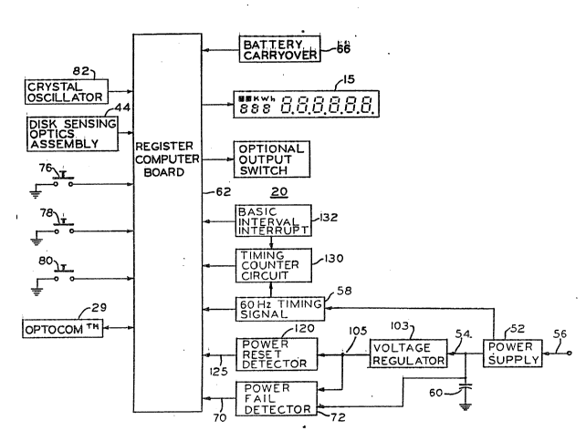
Referring next to FIGS. 2 and 3. The electronic register 20
includes the register computer board 62 which contains a ROM
memory, a RAM memory and the central processing unit or
microprocessor 61. A plurality of inputs are provided to the
microprocessor 61 on the regi~ter computer board 62 including the
output of the disk sensing optics assembly 44 which provides pulses

343~)

11 ME-234
responsive to the rate of energy consumed by the load being
metered, and inputs from the optical coupler 29.
As shown in FIG. 4, ~he unregulated power supply 52 includes
an input trans~o~er 88 supplied by the AC power lines 56 to the
primary winding 900 A diode bridge 93 including diodes 94, 96, 98~
and 100 is connected across the secondary winding 92 of transformer
88. The filtPr capacitor 60 is connected across the power supply
output voltage 54, with one side connected to ground 102, to
provide filtering and also to maintain the electronic register DC
power during brief power outages. Power supply 52 thus supplies DC
power 54 to the register computer board 62, and receives electrical
energy from the AC power lines 56 from which the load being metered
obtains electric energy. The power supply 52 also provides a
timing signal 58 to the register computer board 62, which in the
case of a 60 Hertz power line 56 would be a 60 Hertz signal as
indicat~d in FIG. 3.
When a power outage occurs, the unregulated voltage across the
filter capacitor 60 of tha register power supply 52 begins to
decay. When the DC voltage on the capacitur 60 reaches the
predetermined or preset power fail threshold, a power fail
interrupt signal is provided to the regis~er computex board 62 by
the power fail detector 72. The power fail detector circuit 72 is
shown in FIG. 5. Referring to FIG. 5, the power fail detector
circuit 72 monitors the unre~ulated supply voltage S4 from the
power supply 52. The voltages 105 and 107 are provided from the


11 ME-234
voltage regulator 103 connected in series with the output 54 of the
power supply 52. When the threshold voltage 111 established by the
ratio of the resistors 106 and 108 ~.ops below the reference value
established by a zener diode 113, comparator 110 will go low
causing transis~or 112 to turn of~, sending a power fail signal 70
to ~he microprocessor 61 and inter~pting the microprocessor to
send it into the power down mode of operation.
The power supply capacitor 60 thus discharges until the
regulated logic supply voltage 105 which typically is at 5 volts,
drops to the level where the power fail detector 72 is actuated.
This discharge time and delay can be in the order of a second or
seconds for each power outage, and this delay i5 compensated fox as
described below. The carry over battery 66 is connected to provide
power fsr the electronic register 20 during the power down mode o~
operation. The carry over battery 66 is a non-rechargeable single-
cell lithium battery, and is normally isolated from the 5 volt
re~ulated power supply voltage 105 by a reverse-biased diode. When
the regulated power supply 105 drops below the voltage of the car~y
over battery 66, its isolating diode becomes forward biased and the
c~rry over battery is connectPd to power the electronic register
20. The carry over battery 66 is sufficient to maintain all data
stored in the RAM memory of the microprocessor 61 and also maintain
power dswn operation of the microprocessor.
In the power down mode of operation, the microprocessor 61
"shuts down" operation to conserve power, and the li~uid crystal

f-3~


11-ME-234
display 15 is turned off. Beoause the programmable output switch
is a latching type relay, it retains its la~t state. While in the
power down mode of opexa~ion, the microprocessor 61 maintain~ power
outage time and monitors the power line 56 to determine i~ power
has been restored. During power ou~:ages and power down operation,
no switch inputs from demand reset switch 76, display switch 78 or
test switch 80 is recognized, and no display action is displayed by
the liquid crystal display 15, and no output activity occurs.
Outage timekeeping is done, using the crystal oscillator 82 input
to the microprocessor 61 as the secondary time ba~e during such
extended power outages. The normal frequency of the crystal
oscillator, as determined by its crystal is 32,?68 Hertz.
When the power fail signal 70 goes low the microprocessor 61
recognizes that power has been restored, and the microprocessor
"starts up." The microprocessor 61 must then bring the clock and
calendar up to date, since only elapsed time was accumulated during
the power outage. All of the checks of the time of use schedules,
programmable dates, and similar data are accomplished in the same
manner as in real time operationO Display function at liquid
crystal display 15 and output functions are not provided during
this "catch up" period. When all the time accumulated during the
power outage as descri~ed below is added to the register clock, the
microprocessor 61 is then caught up to the current time. At this
time, the elec~r~nic register 20 will be at the proper date and
ti~e, the season and time of use date will be


~' '

;;2C)3~3~
ll-ME-234
updated to the current schedule, and the electronic register 20
will begin its normal mode o~ operation.
The "catch up" period takes approximately one-half second per
hour of power outage. After a two-day pow~r outage, fox example,
the electronic register 20 could take abou~ as long as 24 seconds
to "catch up." During this time, the electronic register 20 will
display all 8~s as shown in FIG~ 3 and not respond to the reset
switch 76, display switch 78, or to the programmer. However, the
electronic register 20 does count 60 Hertz pulses and al50 counts
input signals or input pulses from the disk sensin~ optics assembly
44 representing energy consumption by the load beiny metered during
the "catch up" period. A ~ast ~catch up" method is used for power
outages lasting more than one day, allowing 90 days of power outage
tLme to be "caught up" in about 30 seconds.
Th2 number of minutes the electronic register 20 was on
battery carryover 66 is added to the cumulative total of time on
battery carryover and is selectable for display. Time on battery
carryover is maintained as an aid in determining the expected
useful life of the battery 66 and when the battery should be
replaced. Time on carryover can be reset to zero with the Register
Programmer each time a new battery i~ install~d.
As mentioned abo~e in a number of contexts, one of the most
impoxtant ~unctions of the electronic register 20 is to keep time.
The primary time base is the 60 Hertz input 56 which is used for
the clock and calendar ~unctions o~ the electronic register 20.

~1~3~3~ 3~
11-ME-234
This is accomplished by having the 60 H~rtz timing ~ignal 58
interrupt the microprocessor 61, causing the microprocessor to
racognize that another 1/60th of a second has passed~ When 3600
interrupts (on 60 Hertz operation) have occurred, one minute has
passed and the clock time .is updated. At each quarter hour, the
time of use schedule is checked to cletermine if a time of use rate
change should occur, or if a load control action should be
activated. Every four quarter hours, the hour is updated. The
time display encompasses 00 throuyh 23 hours and 00 through 59
minutes with 00 hours and oo minutes bein~ midnight. Every
midnight, when the day changes, it is checked to determine i~ it
was the last day of the month and, if reguired, will change the
date to the first day of the following month. The date is
displayed in a six~digit format such as day/month/year~ The last
day of the month is determined from a table stored in the ROM
memory and February 29th is added every four years, on leap year.
In addition, the time of use or demand register 20 accurataly
programs in ~eason changes, holidays and daylight saving tIme since
billing is frequently dependent upon such factors.
It is thus apparent that accurate billing is dependent on
accurate time keeping. ~he electronic register, for example, will
record the date and time of the maximum energy demand by the load
being metered as well as the ~ive highest demands which are
independent of the time of use or discounted periods.
However, the filter capacitor 60 at the outpllt o~ the power

12


,:


3~3
11-ME-234
supply 52 is necessarily of a large capacitance in order that it
will not respond to extremely short or momentary power outages.
Relatively short power ou~ages of ~.he type which may cause lights
to flicker, or dim momentarily, and which are frequently
encountered, for example during electrical storms, do not interrupt
the operation described above; th,at is, they do not cause the
actuation of power fail detector 7:2, ~he take over by carry over
battery 66, the power down mode of operation of the microprocessor
61, and backup timekeeping utili~ing crystal oscillator 82, as
described above. Instead, capaeitor 60 maintains operating power
during such momenta~y power outage~.
However, particularly if the power consumption by the
electronic register 20 is at a minimum or low value, and if the AC
line voltage on the power lines 56 is at a hi~h level ju~t before
a power outage which is longer than the momentary type, there may
be a relatively long delay be~ora the electronic register 20
recognizes the power outage, and this delay will result in the
electronic register losing time. The capacitor 60 under such
conditions will maintain a power on condition by maintai~ing ~he
power supply output 54 at a level above that which will activate
power fail detector 72. During ~his time, the 60 ~ertz timing
signal circuit 58 is not raceiving an input, and time will be lost
during ~he period it takes for the capacitor 60 to discharge
adequately for the power fail detector 72 to detect the presence of
a power outage. The operation o~ the present invention to

;~)3~
ll-ME 234
compensate ~or that period of time is illustrated by way o~ the
block diagram in FIG. 5 and the ~planation of its operation may be
assisted by the algorithm s~t forth below, which is included ~or
completeness of description.


_
ALGORITH~:
START Basic Interval Interrupt

toggle odd count bit (ODDFLG)
IF odd count bit is clear
incr~ment internal counter tPHZCNT)
ENDIF
END BASIC Interval interrupt
*
START 60 Hertz Interrupt
*


zero PHZCNT
END 60 Hertz Interrupt

*
*


START Power Fail Interrupt
*


REPEAT
turn off main clock
REPE~T
switch to HALT mode
sleep for one half second ~ntil watch mode interrupt
add one half second's hertz count to hextz count (PHZCNT)
IF PHZCNT ~= hertz per minute (CPNNUM)
subtract one minute's hertz count from PHZCNT
increment power dow~ minute coun~er (PMNREG)
ENDIF
UNTIL power is on
*
*
IF PHZCNT >= hertz per minute (CPMNUM)
subtract one minute' 5 hertz count from PHZCNT
increment power do~n minute counter (P~NREG)
ENDIF
turn on main clock

14


- ,
; ~ '
,

.

. ~

~3l'13~
11-ME-234

~NTIL power is still on
*
subtract elapsed hertz colmt (PHZCNT) from hertæ count
(HRZCNT)
IF HZCNT ~= 0
add cycles per minute (CPMNUM) to HRZCNT
increment elapsed minutes (PMNREG)
ENDIF
*
END Power Fail Interrupt


Referring to the algorithm above and to FIG. 5, time is kept
for performing the various timing functions described above by
monitoring the line frequency 56 thr~ugh the 60 Hertz timing signal
58 and generating an interrupt for every line frequency cycle, that
is, for every 16 2/3 milliseconds at 60 Hert~. However, the basic
interval interrupt or operating pulses utilized in the electronic
register Z0 during which the emitter/detector pairs in disk sensing
optics ass~mbly ~4 are pulsed is 7.8125 milliseconds, or slightly
more than twice as fast as the line frequency. The basic interval
interrupt ~requency is provided by the primary system oscillator
which oscillates at 4.194 Megahertz. Time is kept by monitoring
the power line frequency and generating an interrupt for every line
frequency cycle and decrementing a timing counter circuit (HRZCNT)
130. When HRZCNT 130 reaches zero it is set to ~he number of
cycles in one minute 3600 (CPMNUM) and th2 system time is
incremented by one minute, that is one minute is added to the
ti~ekeeping of elactronic register 20.
The basic interval interrupt 132 i5 used to account for the
time which would be lost between a power outage and actuation of


;~3~3~Cl
11 ME-234
power fail deteckor 7~. To account for this time, an internal
counter (PHZCNT) is used and read only when a power outage occurs.
The adjusted time will be ~ast because ~he basic interval timer is
approximately 6.6% faster than the 60~z line frequency. When a
register starts for the fixst time, PHZCNT will be set to zero~
PHZ~NT is then incremented every other time the basic interval
interrupt is entered. Every time the line frequency interrupt is
entered P~ZCNT is cleared. Because the basic interval and the 60~z
interrupts are asynchronous, the next odd count will occur between
0.Oms and 15.625ms after the 60Hz interrupt occurs.
When a power fail is detected, PHZCNT is used to keep track of
the time during the power outage. The register "wakes up" Pvery
1/2 second and 30 (cycles) is added to PHZCNT. If PHZCNT is
~reater than or equal to CPMNUM, CPMNUN is subtracted from PHZCNT
and the n~mber o~ minutes accumulated duri~g the present power
outage (PMNREG) is increme~ted. When the power outag~ is
completed, PHZCNT is used to adjust HZCNT 130 and PMNREG.
While the pres~nt inven~ion has be~n described for use with 60
Hertz power lines, it is equally applicable to other power line
~requencies, such as 50 ~ertz, by adjustment of the tlmers or
counters and the algorithm to 50 cycle operation.
Thus, ~hile the present invention has been dascriked through
pr~ferred embodiments, such embodiments are provided by way of
example only. Nu~erous variations, chanqes and substitutions,

including those discussed above will oceur to those skilled in the
art without departing from the scope of the present invention in
the following claims.
16


`
.

Representative Drawing
A single figure which represents the drawing illustrating the invention.
Administrative Status

For a clearer understanding of the status of the application/patent presented on this page, the site Disclaimer , as well as the definitions for Patent , Administrative Status , Maintenance Fee  and Payment History  should be consulted.

Administrative Status

Title Date
Forecasted Issue Date Unavailable
(22) Filed 1991-01-17
(41) Open to Public Inspection 1991-10-06
Dead Application 1996-07-17

Abandonment History

There is no abandonment history.

Payment History

Fee Type Anniversary Year Due Date Amount Paid Paid Date
Application Fee $0.00 1991-01-17
Registration of a document - section 124 $0.00 1991-07-05
Maintenance Fee - Application - New Act 2 1993-01-18 $100.00 1992-12-10
Maintenance Fee - Application - New Act 3 1994-01-17 $100.00 1993-12-02
Maintenance Fee - Application - New Act 4 1995-01-17 $100.00 1994-12-15
Owners on Record

Note: Records showing the ownership history in alphabetical order.

Current Owners on Record
GENERAL ELECTRIC COMPANY
Past Owners on Record
BALCH, RICHARD A.
Past Owners that do not appear in the "Owners on Record" listing will appear in other documentation within the application.
Documents

To view selected files, please enter reCAPTCHA code :


To view images, click a link in the Document Description column. To download the documents, select one or more checkboxes in the first column and then click the "Download Selected in PDF format (Zip Archive)" or the "Download Selected as Single PDF" button.

List of published and non-published patent-specific documents on the CPD .

If you have any difficulty accessing content, you can call the Client Service Centre at 1-866-997-1936 or send them an e-mail at CIPO Client Service Centre.


Document
Description 
Date
(yyyy-mm-dd) 
Number of pages   Size of Image (KB) 
Drawings 1991-10-06 4 104
Claims 1991-10-06 17 727
Abstract 1991-10-06 1 27
Cover Page 1991-10-06 1 16
Representative Drawing 1999-07-05 1 21
Description 1991-10-06 16 705
Fees 1994-12-15 1 54
Fees 1993-12-02 1 45
Fees 1992-12-10 1 46
Fees 1992-12-10 1 44