Note: Descriptions are shown in the official language in which they were submitted.
1
ADAPT' I VE D I VERB I TY EQU I BST ARRANGE~l~T
FOR CELLUIsAR MOBILE TELEPHONE SSiSTEMS
FIELD O~" THE I~d~I3TI0hd
The invention relates to improvements in
cellular telephone base stations.
BACitGR.OTJND AND SU1~AR'Y OE THE I'IOI~
45MR00619
d~ ~ rJ~
Contemporary cellular mobile telephone systems
conventionally include a "diversity" system of some
nature in the base or fixed station receivers to
reduce the effects of multipath fading wherein large
rapid fluctuations of signal le~rel occur. In such
diversity systems the signals received by two or
more antennas are normally made available to the
receiving equipment and a process or scheme is
provided whereby when the signal from one antenna is
experiencing a large negative fluctuation or deep
fade the signal from another antenna may be
substituted. Such switching thus produces a signal
level of higher average signal strength, and the
quality of communications is inherently improved.
A typical such diversity system associated with
receiving equipment is illustrated in Figure 1 which
is a simplified block diagram illustrating a single
channel. In a typical such system~each antenna
.c:anventionally may serve many channels through a
multicoupler. Although such multicouplers are not
illustrated in subsequent fic~.ires, the e.~cemplary
embodiments found therein may be assumed to include
such multicouplers. As illustrated in Figure l,
45MR00519
ff~ ~.:~ ~ ~ ~.
such systems are provided with two receivers per RF
channel, and each receiver has an antenna input and
audio output as well as a received signal strength
indicator (RSSI) output. The latter output is an
analog output which is indicative of or provides a
measure of the received RF signal strength at the
antenna input. A comparison of the RSSI receiver
outputs is made to determine the larger of the two,
and the generated high or low signal may be used to
operate a switch such as SW1 so as to select the
input for the audio processing element from the
receiver with the highest RSSI signal. Such a
diversity scheme is known as a "post-detection
receiver selection by RSSI'° and is in common use. ,
It is else known to use the RSSI or "received
signal strength indicator" for other purposes such
as determining when it is necessary to hand off or
transfer the communications function to another
cell. Such a determination rnay be made by
converting the RSSI measure to a digital format for
transmission to a central processor for comparison
with similar signals from other cells so that the
cell having the strongest signal from the mobile
unit may be determined. The RSSI signals may be
used for these and other purposes through the.use of
a sampling switch means (SW2), an analog-to-digital
converter and the logic unit as illustrated in
Figure 1.
Diversity circuits where the instantaneously
larger of the input signals is passed to the
receiver, operate with sufficient speed to follow
the rather large and rapid fluctuations of the
received signal strength that are present due to
45MR~0619
3
s s ~ ,~
8 ~ ~ l~ t
9
multipath fading. Determining when to transfer or
hand off the communications function to another
cell, however, is not dependent on rapid
fluctuations but is dependent on the mobile position
and average signal strength. Accordingly, both
instantaneous and average signal strengths must be
determined.
As seen in Figure 1 two receivers and two
antennas are required for each area to be covered.
However, in areas where 'the number of subscribers is
quite high it is necessary to provide smaller cells
and re-use frequencies in cells that are relatively
close to each other in order to provide a
sufficiently high number of channels to handle the
communication traffic. Tn such areas it is
conventional to subdivide cells into sectors and use
directional antennas to reduce interfering signals
from other cells. Each sector would require two
antennas and two receivers for maintaining diversity
as noted above. Where a cell, for example, is
divided an'to three 120° sectors, six'receiving
antennas would be required. When the cell is
further divided, maintaining diversity would lead to
a prohibitively large number of antennas and
overcrowding of support towers and the like.
Clearly, under such circumstances it would be
desirable to provide the benefits of diversity but
with fewer antennas being required in each sector of
a cell.
We have discovered that effective diversity
with only one receiver antenna in each sector of a
sectored cell may be obtained through the use of
"adaptive'° diversity. Such diversity dynam9.cally
45MR00~1g
4 ~ #! ,.7
J~ w ~ ~~ iJ. ~ ,1
adapts to changing signal conditions wherein an
analog comparator accepts RSSI signals from two
receivers and the receives operate to receive the
signals from three sectors of a sectored cell; one
receiver being connected to the center sector
antenna and the otkaer receiver being switchably
connected between left and right adjacent sector
antennas. Effective diversity is maintained (for a
large portion of the time) between the center sector -
and one of the adjacent sectors. For very short
periods of time the audio is taken from the center
sector only while the second receiver measures RSSI
in the other adjacent sector. By keeping track of
average signal levels in both adjacent sectors we
can adaptively determine which adjacent sector has
the largest average signal and use it during the
large time period when diversity is in effect.
Such adaptive diversity method and apparatus
not only maintains diversity where large rapid
fluctuations of signal level occur but also
dynamically adapts to changing conditions due to
movement of the mobile unit. Thus, the shortcomings
of the prior art are overcome.
These and further objects and advantages of the
present invention will become more apparent upon
reference to the following specification, appended
claims and drawings.
B~.taE~' DESCItIP'~ION OE Tf3E D1RA~IPrGS
FIGURE 1 is a diagram of a prior art base
station including a diversity system whereby the
strongest of the two audio signals received by two
45MR00619
antennas is used to maintain a higher average signal
level;
FIGURE 2 shows part of a cell which has been
divided into a number of sectors with each sector
including a directional antenna;
FIGURE 3 illustrates a manner in which adjacent
sector diversity may be obtained using three
directional antennas and three receivers;
FIGURE ~ shows an attempt to provide adjacent
sector diversity with only two receivers and three
antennas;
FIGURE 5 illustrates the preferred exemplary
embodiment for obtaining adaptive diversity in a
sectored cell;
FIGtIRES 6A to 6D show portions of a timing .
diagram of the methodology followed by the exemplary
structure of Figure 5; and
FIGURE 7 is an exemplary embodiment similar to
that which is found in Figure 5 illustrating
additional variations thereof.
DET.i~IhED DESCFtIPTIOPd O&' TklE I)R~eVirl~G~
Ae illustrated in Figure 2) a cell may be
divided into a number of sectors with each sector
including a directional antenna. Tdeali~ed signal
level contours of equal signal level for two of the
CA 02034401 1999-08-19
6
45MR00619
sectors labelled S and RA are also illustrated.
Such contours show that although the maximum signal
will normally be obtained by an antenna from a
mobile located within the boundaries of the sector
containing the antenna, signals of only a little
less amplitude can be obtained by an antenna
located in another sector. Similar antenna
propagation patterns, although not illustrated,
also apply to the left adjacent sector LA.
As illustrated in Figure 2, a particular
mobile is located in sector S at the point M, and
it is clear that the antenna in sector S will be
receiving the mobile signal at some average level.
The antenna in sector RA (right side adjacent
sector) will also be receiving the mobile signal
but a reduced average level. Depending on the
location of the mobile the average signal level
received at RA will range from nearly equal to that
detected by the antenna in sector S to a few dB
lower than the signal received at S. The former
situation would occur, for example, when the mobile
was on the sector border; whereas, the latter would
occur with the mobile in the center of sector S.
Under such circumstances if multipath fading
phenomena occurred in sector S (fading in the range
of 20 to 30 dB), the signal from RA for the
duration of the fade may be on the order of 10 or
20 dB stronger. Similar signal levels and
conditions may be found in the left adjacent sector
LA when the mobile is on that side of sector S.
Clearly, by using the signals from the sectors
adjacent the S sector, effective diversity may be
provided with only one receiving antenna in each
45MFt00619
,.
sector. Additionally, it is clear that if the
average signal level in an adjacent sector.such as
RA becomes larger than the'average signal in sector
S, the conditions are such that a transfer to the
former sector, i.e. a handoff, would be appropriate
since the mobile is no longer truly within sector S.
' Apparatus for obtaining such~diversity and
handoff transfers is illustrated in Figure 3 which
differs from that which is shown in Figure 1 in that
three receivers 1, 2 and 3 are provided with three
RS~r.branch paths being compared by element 4 where
the latter element operates as a thre~ pole
switching arrangement for feeding the strongest
audio signal to the base station audio processing
system 5, That is to say, if the strongest
instantaneous signal is received by sector S antenna
6, switch SW1 connects receiver 2 of sector S to
element 5. With multipath propagation fading
phenomena present in sector S, either sector RA or
sector LA would furnish the audio input to element 5
depending on which sector had the strongest signal.
Although such a system is clearly operable, it
has the disadvantage of the additional expense
incurred by rewiring a third receiver. As
illustrated in Figure 4, a two-receiver system for
providing adjacent sector diversity is obtainable by
connecting the adjacent sector antennas 6 and B to
.the second receiver and controlling the illustrated
switch positions through the use of digital logic
9. The dotted lines indicate one or more switch
control signals which allow the logic circuits to
exercise control over the switches. Switch SW2
allows the analog-to-digital converter to measure
45MR00619
8
'~~ ~,o f ~a rf y.: F.~J
RSSI samples from either receiver. The antenna
switch AS6J allows receiver 2 to be connected to
either of the adjacent sector antennas (6 and 8).
Under initial conditions the audio is, as
illustrated, connected from receiver 1 by way of SW1
to audio processor 5. Additionally, the RSSI signal
from receiver 1 is connected to converter 10 by way
of S~d~. Logic 9 would measure the received signal
strength indicator (RSSI) of sector S arid thereafter
the logic would connect converter 1t~ to receiver ~'
and male similar measurements in each of the
adjacent sectors in a sequential manner.
A comparison of the measurements by the logic
element would indicate the highest signal strength
and set the switches appropriately. If the RSSI in
sector S, for example, were the largest measured,
the audio switching would be as illustrated in the
figure. Thereafter, the measurement cycle would be
repeated and an adjacent sector such as LA or RA
would be connected for providing the audio input to
element 5 if it provided the strongest signal as
indicated in the subsequent measurements. Logic
unit 9 operates the antenna switch in a fashion
similar to SW1. That is to say, in each measurement
cycle the adjacent sector having the largest .
measured RSSI would be connected to receiver 2 and
would be changed only if a subsequent measurement
indicated that the other adjacent sector RSSI were
stronger.
Although such a system requires only two
receivers, the analog comparator has been replaced
by a sequential digital RSSI measurement routine
wherein the receiver whose audio output is not being
k
45MR0061g
transmitted to element 5 is being used to measure
signal strength in the adjacent sectors. Although
this process is wor3~able 'in principle as to
providing audio improvement due to diversity
switching, practical implementation presents a
problem since the measurements are no longer being
made in a simultaneous manner. That is to say,
significant fades in the sector signals may occur
many times a second and last for only a few
milliseconds. In order for diversity to provide
improved signal quality substantially instantaneous
switching is required when multipath fading is
sensed. To obtain such instantaneous switching, the
entire process of switching antennas, acquiring and
evaluating new RSSI measurements and switching the
appropriate audio output signal to processor 5 must
be completed in no more than a couple of
microseconds in order for diversity to be
effective. Such high performance sequential circuit
designs are difficult to obtain and expensive.
Accordingly, such circuit designs would not be well
suited fox obtaining competitive commercial products.
As previously noted, we have discovered a
manner and means of overcoming the shortcomings of
the previously described arrangements. The
exemplary embodiment of Figure 5 is an arrangement
fox obtaining effective diversity with only one
antenna in each sector of a sectored cell and with
.adaptive diversity obtained through the use of
structure which dynamically adapts to changing
signal conditions due to movement of the mobile, as
well as the effects of multipath fading.
45MROOC19
r~
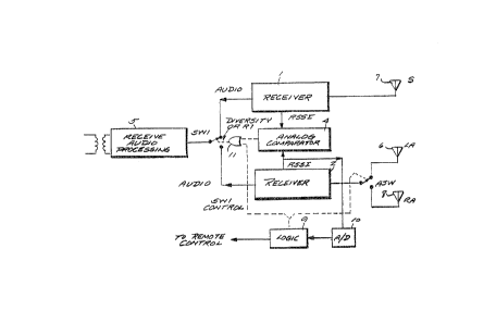
The structure uses an analog comparator which
obtains RSSI signals from two receivers) wherein the
comparator owtput is connected to switch SW1 by way
of a logical OR-like switching structure 11 which is
symbolically shown. Such OR structure allows (under
the control of logic element 9) a diversity
operation between the output of receiver 1 and the
output of receiver 2 or requires the audio output
from receive 1 to be passed by way of switch SW1 to
processor 5 for short periodic intervals. During
the short periodic intervals, receiver 2 is used to
measure the RSSI from the left and right adjacent
sectors by using elements 9 and 10 to determine
which adjacent sector is producing the strongest
signal and, therefore, which sector antenna is to be
connected to receiver 2.
The process may be understood by again
considering the example illustrated in Figure 2
where the mobile is located at M which is closer to
sector RA than to sector LA. The signal in sector
RA, accordingly, will be stronger than the signal
sensed by antenna 6 in sector LA. If the location
of the mobile unit were known in advance, the
operation of the antenna switch ASW to select RA for
connection to receiver 2 would be a foregone .
conclusion and easily implemented. Although such
information is not available in advance, the
invention takes advantage of two facts; namely, (a)
that the location of the mobile unit within a cell
changes relatively slowly compared to the rather
rapid fluctuations of multipath fading, and (b)
improvements in the recovered audio due to effective
diversity is a statistical process which obtains
45MR00619
11
improved duality of communications by reducing 'the
ayerage noise level in the recovered audio. As to
the first noted fact, although multipath fading must
be overcome by the rapid switching provided by a
diversity system, since the average signal level
changes slowly, it is possible to determine the
average signal level by making less frequent
measurements than is required for maintaining
diversity.
We have discovered that effective diversity can
be maintained for a large portion of the time, fox
example 90% of the time, and that the resulting
improvement in duality is substantially equal to
that obtained where diversity is maintained 100% of
the time. We have further discovered that average
adjacent sector signal levels may be obtained by
taking periodic short samples of the RSSI in the
adjacent sectors and that such samples provide a
measure which indicates which adjacent sector has
the strongest signal and, therefore, the position
which should be assumed by switch ASW. Under such
circumstances receiver 2 can be connected to the
antenna of the adjacent sector with the strongest
signal as well as the analog comparator and
thereafter provide effective diversity between
sector S and the strongest adjacent sector. As
afarmentioned, said diversity periods are relatively
long, such as 90% of the period. During the short
periodic samples when the relative signal strengths
of the adjacent sectors is measured, logic element 9
by way of OR structure Z1 farces switch SW1 to
connect the receiver 1 audio to processor 5.
Accordingly, during all portions of the period an
45MFt00619
m ~~~;',,
,_
audio signal is applied to the processor 5, albeit,
without diversity during the short sampling or
measuring periods. However, the worst that can
happen during the short measuring period would be a
deep fade in the signal from the antenna in the S
sector, which, of course, could happen during the
measurement process. Statistically, however, such
deep fades occur much less than 50% of the time
during multipath fading. As such the average signal
strengths may be maintained at a high signal Level,
and consequently, the quality of communications is
improved through the use of a relatively simple and
inexpensive circuit design which is well suited for
inclusion in a competitive commercial product.
The process of the exemplary embodiment of
Figure 5 may be more fully understood from a
consideration of the timing diagrams illustrated in
Figures 6A to f~D. Figure 6A illustrates that
diversity is effective, i.e., SW1 continually
selects the strongest of the two receiver audio
output signals, except when measurements are made
during the relatively short sampling periods. As
illustrated in Figure 6B, during the relatively long
diversity periods the switch SW1 may connect either
of the receivers to the audio processor 5 but. during
the relatively short measuring periods only receiver
1 is connected to element 5. Figure 60 indicates
w_ h:ich . antenna ( f~ or 8 ) i s connected to the second
receiver by way of switch ASW at any particular
time. The particular antenna cann~ected, of course,
will depend upon the measured signal strength from
the antennas which are sampled in the timed manner
illustrated in Figure 6D.
45MR00619
13 ~H~rai~ ~~ ~~.;
Considering the timing cycles of Figures 6A to
~D together at time TO when diversity is active
between sectors S and LA,' sector RA and its antenna
are inactive in the sense of not being connected to
receiver 2. At time T1, although diversity is still
active, the RSSI of the active sector LA is sampled
and measured at the converter 10, and logic 9 then
controls SW1 to select the audio from receiver 1 for
transmission to processor 5. Simultaneously, the
logic element 9 operates switch ASW to connect
receiver 2 to the "inactive" RA sector and at time
T2 the RSSI of sector RA is sampled and measured.
The time difference between T1 and T2 is critical
only to the extent of allowing sufficient time for
the signal strength of receiver 2 to settle to its
new value after the operation of the antenna switch
ASW. A comparison is then made by logic element 9
to determine whether the signal strength of sector
LA or RA is strongest, and the positioning of swatch
ASW is made in accordance with the determination.
Thereafter, logic 9 allows switch SYJ-1 to again
operate in a diversity mode.
As illustrated in Figure 6C, the right adjacent
sector at time T2 would be determined to be larger
than the left adjacent sector LA such that when
diversity is reactivated, the active sector is
changod from adjacent sector LA to adjacent RA.
Additionally, in the period between T2 and T3,
Idiverslty is active between sector S and sector RA
with LA "inactive". Moreover, as clearly
i.llus~trated in Figure 6A, at the end of time T3 a
new measurement cycle begins but with sector RA
measured during the active diversity period and
451~IR00619
14 ~;~~ja;~k;
.~ ~.; e.i
sector LA measured when SW1 is forced to connect
receiver 1 to processor S.
Accordingly, the exemplary embodiment of Figure
provides a circuit design that not only provides
high quality communications but provides such
results with a design well suited to a competitive
commercial product. Moreover, the problems of the
prior art are avoided by dynamically adapting to
changing signal conditions whereby effective
diversity is obtained to combat the effects of
multipath fading as well as changing signal
conditions due to movement of the mobile unit. The
latter condition is measured for the purpose of
using the strongest sector signal as well as
determining when cell-to-cell transfer or handoff
should occur.
Figure 7 illustrates variations of the
exemplary embodiment of Figure 5. For example, the
RSSI of sector S and receiver 1 may be measured and
stored in logic 9, and the RSSI of additional
sectors may also be measured during the periodic
short samples of adjacent and other sectors, said
other sectors being represented by sector S and
antenna 12. The measuring of additional such signal
strength samples may be used fox storing average or
rolling values or for comparison purposes with the
RSSI of sector S along with other RSSI's for
determining, among other things, the need for
cell-to-cell transfer or handing off. Additionally,
the inclusion of other sectors in the diversity may '
take into consideration the RSSI Of the sector
diametrically opposite from the S sector in order to
handle the case where the mobile unit is passing
45MR00619
substantially directly under the antenna tower
through the center of the cell.
Still other variations will occur to those
skilled in the art. For example, logic unit 9 may
be advantageously designed to choose or base its
decisions on more than one sample of RSSI from a
particular sector. Such decisions may be based upon
maintaining average readings of RSSI from each
sector and updating the averages at each measurement
cycle. The choice of which receiver to use when
based upon such average signals is indicative of the
position of the mobile unit and such averages would
vary slowly.
Additionally, the artisan will recognize that
the sequence in which the switches are operated and
the measurements taken may be varied within the
teachings of our disclosure. In Figures 6A to 6D,
for example, the time during which diversity is
active can be maximized by making the order in which
the adjacent sectors are measured dependent upon
which sector is currently active. Such an
operation, however, is not necessary and the logic
may be simplified by making the order fixed and
extending the diversity inactive period to cover
measurements of both adjacent sectors. Still
further, the artisan will recognize that
contemporary circuit elements may be used to
implement the exemplary embodiments illustrated and
described. For example, the switches such as SC~~.
could be implemented with commercially available
solid state devices such as CMOS transmission
gates. Addi't:ionally, the antenna switch ASW could
also be a solid state device such as a pin diode RF
45MR00619
16 c~, :$6. (~ 5 y a
~~~a~i~~j °)
switch: Stil1 further, the logic element 9 could be
easily implemented by way of programming
conventional microprocessogs.
While the invention has been described in
connection with what is presently considered to be
the most practical and preferred embodiment, it is
to be understood that the invention is not to be
limited to the disclosed embodiment, but on the
contrary, is intended to cover various modifications
and equivalent arrangements included within the
spirit and scope of the appended claims.