Note: Descriptions are shown in the official language in which they were submitted.
Z034575
- 1 -
GARBAGE DISPOSER
BACKGROUND OF THE INVENTION
l. Fleld of the Invention
The present invention relates to an apparatus for
disposal of wet garbage f rom a kitchen. More particularly,
the invention relates to a garbage disposer which pulverizes
garbage, drys it and discharges only the resulting water into
a sewage system.
2. Description of the Prior Art
The garbage disposer is a well-known device for disposal
of kitchen garbage. The disposer is generally attached to the
drain line of a kitchen slnk and adapted to comminute the
garbage so that Lt can be discharged into a sewage system.
However, when the garbage is thus finely-divided and
discharged directly into a sewage system, the contamination of
sewage water is so serious that a great processing burden is
imposed on the downstream disposal plant. Furthermore, if
such a device is used in an area where the sewage water is
not further processed but discharged directly into a river or
the sea, it presents a serlous enviromental problem.
SUMMARY OF THE INVENTION
The present invention has been conceived and accomplished
to overcome the drawbacks of the prior art garbage disposer.
It is, therefore, a primary ob~ect of the present
invention to provide a garbage disposer which comminutes
garbage with high efficiency, drys the comminuted garbage and
discharges only the . 1 water lnto a sewage system with
the L l Llt:LIt solid matter being retained to thereby minimize
- 2 - Z034575
the pollution of sewage water, thus contributing to
alleviation of burdens on the ~UWII~BL'~ -- sewage disposal plant
and prevention of pollutions.
It ls another ob~ect of the present lnventlon to provlde
a garbage dlsposer whlch comprises a pulverizing segment for
commlnutlng he garbage and a dry segment for withdrawing
water f rom the pulverized garbage in an integral combination
whlch is compact and, therefore, space-saving and can be
installed at the sink just as the prior art disposer.
The above and further ob~ects, features and advantages of
the invention will more fully appear from the followlng
descrlptlon with reference to the accompanying dra~ins. It
is to be expressly understood, however, that the drawings are
for purpose of lllustratlon only and are not lntended as a
definltion of the limits of the lnventlon.
BRIEF DESCRIPTION OF THE DRA~JINGS
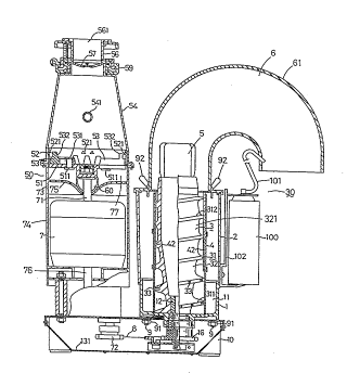
Fig. l is a longitudlnal section view showing a garbage
disposer embodying the prlnciples of the present invention;
and
Flg. 2 is a disassembled perspectlve vlew of the same
d isposer.
DETAILED l~ N OF THE ~ EMBODIMENTS
Referrlng to Figs. ~ and 2, the garbage dlsposer of the
invention comprises a base lû, mounted thereon, a motor 7 and
f~ a garbage drying means 3O as mounted on~ base, and a
garbage pulverizing means 50 disposed on ~ motor 7.
The E~:arbage pulverlzlng means 50 comprlses a crushlng
30 rotor 5l, a crushlng rlng 52, a palr of crushing members 53,
_ 3 _ 2034575
53, a cover 54, a water seal ring 55, a check valve 57, a
charging port 56, a lid 58 and a cf~nn~rt;ng ring 59.
The crushing rotor 51 is directly mounted on an upper
shaft 71 of the motor 7. The outside diameter of the
crushing rotor 51 is slightly smaller than the out8ide
~1;. t~r of the motor 7.
The crushing ring 52 has an inner ~ ti~r slightly
larger than the outside diameter of the crushing rotor 51.
The ~nt~rn;ll wall of the crushing ring 52 is provided with
a plurality of cutout projections 521 f~l~t~n~;n~ inwardly and
the lower edge of the ring 52 is serrated.
The afore3aid pair of crushing members 53, 53 is so
configured that each member is generally elliptical in plan
view and has a crushing projection 532 on the upper face of
its forward end and an elongated groove 531 formed in the
direction o~ its maj or axis at its base . The elongated
grooves 531, 531 of these crushing members 53, 53 are
engaged by pins 511, 511 secured toward the center of the
crushing rotor 51 80 that the rrl~qh;ng members 53, 53 may
respectively slide in the radial direction of the crushing
rotor 51. In this aLLCLlly~LlLe:llt, as the motor 7 is driven to
turn the crushing rotor 51, the respective crushing members
are centrifugally caused to slide toward the outer
circum~erence of the crushing rotor 51 and the locus of the
crushing projections 532, 532 approach the cutout
projections 521 of crushing ring 52 so that the garbage is
pulverized between these crushing projections 532, 532 on
the one hand and the cutout projections 521 on the other
hand .
The aforesaid cover 54 covers the crushing rotor 51 and
crushing ring 52 from above and is configured generally like
Z034~;75
-- 4 -
a truncated cone. This cover 54 is rigidly secured to the
upper end of a case 74 housing the motor 7 with a setscrew
means through a water seal ring 55. A water supply port 541
formed in the peripheral wall of the cover 54 communicates
with a water faucet so that the water necessary for crushing
of garbage can be introduced into the cover 54 through this
water supply port 541.
The charging port 56 is communicable with a garbage
discharge port of a garbage tank at the sink and its top
0 opening 561 is provided with said lid 58 for opening and
closing.
The check valve 57 is separates the cover 54 and the
charging port unit 56 from each other and is made of rubber.
The check valve 57 is formed with a plurality of incisions 571
extendin~ radially from its center. This check valve 57 is
interposed between the top opening of the cover 54 and the
charging port 56.
~~ The connecting ring 59 ~ links the cover 54 and the
charging port unit 56 as a unit.
The garbage pulverizing segment 50 is not limited to the
one described above but may be similar to the crushing segment
of the prior art disposer.
The motor 7 is housed in a case 74 mounted on the base
l O. The upper end of the case ~4 is provided with an inward
partitioning wall 75, forming a free space 7~ between
partitioning wall 75 and the crushing rotor 51 of the garbage
pulverizing segment 50. The upper shaft 71 of the motor 7
extends through this partitioning wall 75, while the lower
shaft 76 is connected to a pulley 72 within the base through a
speed reduction ' ~- not shown.
5 :~03~575
The reference numeral 60 indicates a garbage discharge
port. This garbage discharge port 60 is disposed in the
perlpheral wall 73 of the case 74 housing the motor 7 in such
a manner that it c~ ~n~ tes with~ free space 77 so that
+h~
S the garbage crushed by G~id garbage pulverizing segment 50 is
discharged f rom the pulverizing segment 50 via the space 77.
Connected to this garbage discharge port 60 is a discharge
pipe 601 which, in turn, is connected to a feed pipe 111 on
the garbage charging port 14 via a hose of PVC or the like
0 material ~not shown) as will be described hereinafter.
The garbage drying segment 30 includes a bottom
cylindrical member 1, a rotary shaft 12, a screw 3, a screen
4, a case 2 and a discharge pipe 61.
The cylindrical bottom member 1 has a bottom wall 11 and
is provided with bolt holes 161 circumferentially 90 degrees
apart. The bottom wall 11 is centrally provided with a
through-hole through which ~ rotary shaft 12 is passed.
The cylindrical bottom member 1 is further provided with a
garbage charging port 14 and a water discharge port 15 in
parallel on its peripheral wali. Connected to the garbage
charging port 14 is a charglng plpe 111 whlch, aforesald, is
connected to the discharge pipe 601 on the side of the garbage
dlscharge port 60 via a hose of PVC or the like (not shown).
The inner end part of the garbage charging port 14 forms a
proJecting orifice 17 extending into the cylindrical bottom
member 1. Connected to the water discharge port 15 ls the
water discharge pipe 112 which is connected to a draln plpe
of a sink or a sewage system, for instance, via a hose not
shown.
The rotary shaft 12 is disposed in such a manner that lt
- 6- 2034~75
~'IQ
extends out of ~ base 10 into ~ cylindrical bottom
member 1. This rotary shaft 12 is provided with a pulley 16
at its lower end and this pulley is connected to the pulley 72
on the motor 7 side via a chain or a belt 8.
The screw 3 cooperates with a screen 4 to dry the garbage
crushed by the garbage pulverizing segment 50, and a lower
portion corresponding to about one-third of its length
constitutes a forced feed segment 320, while the r~ ~;n~nE
portion of the screw 3 constitutes a compression segment 321.
0 This screw 3 has a helical blade 31 on the peripheral surface
of its trunk portion 32. The trunk portion 32 is gradually
increased in diameter from the lower end to the upper end.
The helical blade 31 of the screw 3 is gradually reduced in
pitch from the lower end to the upper end, and the outer
diameter of the compression segment 321 is smaller than the
outer diameter of the forced feed segment 320. Furthermore,
this blade 31 has a plurality of anti-wear pins 33 embedded
in the peripheral part of its compression segment 320.
The screen 4 passes water selectively and is
cylindrically configured. The inner diameter of this screen 4
is approximately equal to the outer diameter of the blade 31
at the forced feed segment 320 and the length of the screen 4
is approximately equal to the length of the screw 3. The
lower end of the screen 4 is formed with a cutout 41 for
accepting the projecting orificel7 within the cylindrical
bottom member 1, whereby the garbage is introduced into the
screen 4 from below. The inner circumferential surface of
the screen 4 which corresponds to the compression segment 321
of the screw 3 is provided with four blocking bars ~ for
arresting the flow of garbage in the rotatlonal direction of
~03~7S
- 7 -
the screw 3 at equal intervals. The thlckness of these
blocking bars 42 is so designed that the peripheral surface of
the blade 31 at the compresslon segment 321 of the screw 3
barely contacts the surface of the blocking bars 42.
The reference numeral 5 indicates a stirring member.
This stirring member 5 is adapted to loosen the garbage
compressed and dried by ~ screw 3 and screen 4, and as
mounted on the top of the screw 3, it revolves along with the
screw 3.
The case 2 is a cylin~drical member disposed to enclose
the screen 4. This case 2 has a diameter equal to the
diameter of ~ bottom member 1 and is mounted on a top edge
13 of the bottom member 1 through an O-ring 113. This case 2
has, on the circumferential surface close to its upper edge,
~5 four stationary members 22 each having a bolt hole 21 at
angular intervals of 90 . A deodorant can-mounting member
102 is secured to an appr~priate part of the peripheral wall
of the case 2.
The discharge pipe 61 constitutes a discharge way 6 for
discharglng the crushed and dried garbage and its forward
open end portion is downwardly curved. The base of this
discharge pipe 61, i.e. the ~onnection thereof to the case 2
in its upper position, is provided with a square flange 62.
This flange 62 has bolt holes 63 at four corners. Inserted
through the wall at the open end of this discharge pipe 61 is
the free end of the PVC pipe:101 extending from the deodorant
can 100 mounted on the mounting member 102 of the case 2.
Furthermore, a bag (not shown) for collecting the dried
garbage is attached to the Open end portion of the discharge
pipe 61 with the aid of a band 64.
- 8 - Z034575
The aforementioned cylindrical bottom member 1, case 2
and discharge pipe 61 are Jointed in stack by means of four
elongated bolts 9 erected from within the base 10 and
butterf ly nuts 92 respectively threaded onto the top ends of
5 A~ ~F elongated bolts 9. Thus, the elongated bolts 9 pass
through the bolt holes (not shown~ in base 10, bolt holes 161
in bottom member 1, bolt holes 21 in case 2, and bolt holes
63 in dlscharge pipe 61 in Cl]rrl~C~;r~ and ~butterfly nuts
92 are respectively threaded onto the top ends of these
0 bolts.
The reference numeral 131 indicates a chaln case.
The actions of the garbage disposer of the above
construction are explained below.
First, the apparatus is supplied with electric current to
start the motor 7, whereupon the crushing rotor 51 of the
garbage pulverizing segment 50 and the screw 3 of the garbage
drying segment 3O are simultaneously driven.
The lid 58 of the garbage pulverizing segment 50 is then
removed and the garbage is charged f rom the end opening 561 of
the charging port unit 56, whereupon the garbage under its
own weight pushes the check valve 57 and falls into the cover
54. By this time, the space within the cover 54 has been
supplied with an appropriate amount of tap water for assisting
in smooth crushing of garbage f rom a faucet through the water
supply port 541. When a substantial amount of water entrains
the garbage f rom the garbage tank of a sink into the cover
unit 54 through the charging port 56, the above supply of
water from the faucet is not required.
The water-containing garbage falling into the cover unit
54 is finely divlded between the crushing pro~e-tions 532, 532
Z034575
g
of the crushing members 53, 53 and the cutout proJections 521
of the crushing ring 52.
The wet garbage thus comminuted enters into the free
space 77 below the crushing rotor 51, from which it travels
through the garbage discharge port 60, discharge pipe 601,
hose (not shown), feed pipe 111 and garbage charging port 14
into the screen 4 at the proJecting orifice 17.
The wet garbage introduced into the cylindrical screen 4
is delivered upward by the revolving screw 3. First, in the
(~ forced feed segment 320 of the screw 3, the garbage is
spirally fed upward within the screen 4 as the screw 3
revolves. In this course, the garbage is somewhat dried by a
centrifugal force and the resulting water flows through the
screen 4 into the space between the screen 4 and the case 2.
The partially dried garbage is further pressure-fed upward by
the screw 3 but when the garbage reaches the zone of the
blocking bars 42 of the screen 4, it is arrested by blocking
bars 42 against movement in the rot~ rion~ directlon of the
screw 3 and rises along the bars 42 within the screen 4. In
this connection, since the diameter of the trunk portion 32 of
the screw 3 is gradually larger f rom the lower end to the
upper end and the pitch of the blade 31 gradually diminishes
from the lower end to the upper end as mentioned hereinbefore,
the garbage is progressively compressed as it rises so that
it is efficiently dried. The rcu~tin~; water flows through
the screen 4 into the space between the screen 4 and the case
2. In this manner, the water passing through the screen 4 in
the forced feed segment 320 and compression segment 321 of the
screw 3 is discharged from the bottom of the bottom member 1
into a drain pipe at the sink or a sewage system through the
2034575
- 10 -
o~tscl~,~
water-~e port 15 and discharge pipe 112.
The garbage thus efficiently dried in the garbage drying
segment 30 is loosened up by the stirring member 5 on the top
of the screw 3. The loosened garbage travels through the
discharge way 6 within the discharge pipe 61 and collects in a
bag (not shown~ attached to the open end of the discharge
pipe 61 with the band 64. The dried garbage collected in the
bag is discarded together with other household rubbish for
disposal.
0 Either before or after collection of the garbage in the
bag, a nozzle of the deodorant can l OO is actuated to spray
the deodorant at the open end of the discharge pipe 61,
whereby the malodor of the garbage is cancelled and no
discomfort is felt in removing the bag from the discharge pipe
61.
While there has been described what is at present
considered to be preferred embodiments of the inventLon, it
will be understood that various modif icatiops may be made
therein, and it is intended to cover in the appended claims
all such modifications as fall within the true spirit and
scope of the invention.