Note: Descriptions are shown in the official language in which they were submitted.
203~7 ~ 3
,
Attorney Docket No. 8021-9
PENDANT CONNECTOR
BACKGROUND OF THE INVENTION
The present invention relates generally to
;5 ornamental jewelry, more particularly to a novel device for
attaching a pendant to a decorative chain.
- The prior art provides no reliable method for
;attaching a substantially flat pendant to a necklace or long
chain when the pendant possesses a connecting loop oriented
at right angles to its front face. When a single connecting
loop is used, such a pendant will not hang correctly because
the front face will be at right angles to the longitudinal
axis of the necklace.
:
;SUMMARY OF THE INVENTION
The present invention provides an aesthetically
pleasing solution to this problem by using two interlocking
latching elements. One element is hung from the other by
means of a small eyelet that allows the two elements to be
oriented at right angles to each other and also eliminates
excess play between the two elements. The element bearing
the eyelet possesses a locking bar having a longitudinal
slot that permits the eyelet to engage the other latching
element even after the bar is swiveled to its locked
position.
According to the present invention, a device is
provided for removably attaching a pendant to a decorative
chain, usually a necklace. The device comprises a pair of
interlocking arcuate latching elements. The first element
receives the chain and has an arm swivably attached to one
end which engages the other end of the element when it is
swiveled to a closed position. When the arm is closed, a
locked loop around the chain is formed. The second latching
element receives a connecting loop on the pendant to be
attached to the chain. The second element has a locking bar
'
..
.... . .. . : . :
, ': ~ ~ ' ' ., ' . ' ' ' : -
,
:. . ' . ~' . .: .. ., ' - . -
203~7~3
swivably attached at a point adjacent to an eyelet on one
. .
end. The eyelet is adapted for receiving the first latching
element before its arm is swiveled to a closed position.
~ When the two elements are interlocked in this manner, they
- 5 are oriented at right angles to each other. The use of the
eyelet to interlock the two elements prevents excess play
that would occur if two interlocking loops were used. The
locking bar has a longitudinal opening through which the
eyelet protrudes when the locking bar is swiveled to a
closed position. When the locking bar engages the opposite
end, it creates a closed, locked loop around the connecting
loop on the pendant.
Using the present invention, a pendant which is
substantially flat and has a connecting loop oriented
transverse to the front face can be hung from a necklace.
Unlike the prior art, the claimed device allows the pendant
to be attached so that the front face can be seen because it
hangs parallel with the longitudinal axis of the chain.
; BRIEF DESCRIPTION OF THE DRAWINGS
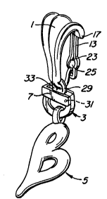
Fig. 1 is a front elevational view of the present
invention attached to a decorative chain and pendant.
Fig. 2 is a side elevational view of the first
latching element of the present invention.
Fig. 3 is a front elevational view of the second
latching element of the present invention.
Fig. 4 is perspective view of the first latching
element of the present invention.
Fig. 5 is a perspective view of the two latching
elements of the present invention
DETAILED DESCRIPTION OF T~E DRAWINGS
Referring now to Fig. 1 the device of the present
invention can be seen to include a first arcuate latching
element 1 and a second arcuate latching element 3. The
device allows a pendant 5 to be attached to a decorative
chain 7, typically a necklace. The first and second
s .
, . .
;. :
.: . . . ~ - .
3 ~34713
latching elements 1 and 3 can be formed by any standard
method known in the art, including, but not limited to, lost
wax molding, casting or the like. The elements can be
formed from any standard material known in the art
including, but not limited to, gold, silver, or brass. In
the embodiment illustrated, the pendant 5 is substantially
flat with a connecting loop 9 oriented transverse to the
front face ll of the pendant 5. The device of the present
invention allows for the attachment of the pendant 5 to a
~ 10 chain 7 such that pendant's front face 11 can be located
- parallel with a longitudinal line generally defined by that
portion of the chain 7 to which the latching element
attaches. Thereby, the pendant 11 is better able to be
; seen. In the prior art, such a pendant could not be
; 15 attached to a necklace because the orientation of the
' pendant would be incorrect.
Referring now to Fig. 2 the first latching
element 1 is seen to include an arm 13 attached to a first
end 15 of the first latching element 1 by a hinge 17. The
arm 13 can be swiveled to a closed position so that the end
19 engages the second end 21 of the first latching
element 1.
Fig. 3 illustrates one embodiment of the present
invention in which the arm 13 is formed to have an aperture
23 at the end 19 of the arm 13 that engages the second end
21 of the first latching element 1. The second end 21 is
formed to have a bulb 25 that prevents the arm 13 from
inadvertently slipping off the second end 21. Preferably,
the arm 13 is constructed to receive and removably capture
the bulb 25, placing the latching element in a latched
condition. For this purpose, the arm 13 is constructed to
have an elongate slit 14 of sufficient resilience to
removably receive and hold the bulb 25.
As Figs. 4 and 5 show, the second latching
element 3 is of two-piece construction: (1) an arcuate
member 26 having a pair of terminating ends 28 and 29 that
de~ine an opening 30, and (2) swivably attached to the
,~'
.. . .
, . .
:: .
..
~03~713
arcuate member 28, at 31, adjacent to the end 29, a locking
- bar 27. Formed in the end 29 is an eyelet 32. The locking
bar 27 is provided, in the top thereof, with a longitudinal
opening 33 (Fig. 5) through which the eyelet 32 is adapted
to protrude when the locking arm is swivelled to a position
that closes the latching element 3, as illustrated in
Fig. 5.
Fig. 5 illustrates the complete device and the
interaction of the first and second latching elements 1 and
3. After a pendant 5 is attached to the second latching
element 3 and the locking bar 27 is locked into place, the
eyelet 29 engages the second end 21 of the first latching
element 1. The arm 13 of the first latching element 1 is
then swiveled into place thus locking the first latching
element 1 to the second latching element 3. At the same
time, the first latching element forms a closed locked loop
around the chain 7, so that the pendant 5 is attached to the
chain 7.
Although the best mode contemplated for carrying
out the present invention has been herein shown and
described, it will be apparent that modification and
variation may be made without departing from what is
regarded to be the subject of the invention.
:
. '
, .
:. :, .