Language selection

Search

Patent 2035079 Summary

Third-party information liability

Some of the information on this Web page has been provided by external sources. The Government of Canada is not responsible for the accuracy, reliability or currency of the information supplied by external sources. Users wishing to rely upon this information should consult directly with the source of the information. Content provided by external sources is not subject to official languages, privacy and accessibility requirements.

Claims and Abstract availability

Any discrepancies in the text and image of the Claims and Abstract are due to differing posting times. Text of the Claims and Abstract are posted:

  • At the time the application is open to public inspection;
  • At the time of issue of the patent (grant).
(12) Patent: (11) CA 2035079
(54) English Title: SCREW TOP
(54) French Title: COUVERCLE A VISSER
Status: Expired and beyond the Period of Reversal
Bibliographic Data
(51) International Patent Classification (IPC):
  • B65D 41/34 (2006.01)
  • B65D 55/02 (2006.01)
(72) Inventors :
  • DEBETENCOURT, JEAN (Belgium)
(73) Owners :
  • L & M SERVICES B.V.
(71) Applicants :
  • L & M SERVICES B.V.
(74) Agent: SMART & BIGGAR LP
(74) Associate agent:
(45) Issued: 1995-09-12
(22) Filed Date: 1991-01-28
(41) Open to Public Inspection: 1991-08-06
Examination requested: 1991-10-23
Availability of licence: N/A
Dedicated to the Public: N/A
(25) Language of filing: English

Patent Cooperation Treaty (PCT): No

(30) Application Priority Data:
Application No. Country/Territory Date
90870020.6 (European Patent Office (EPO)) 1990-02-05

Abstracts

English Abstract


The invention relates to a screw top comprising
essentially two elements formed by a skirt and a sealing ring connected
together in a number of places by means of small cross-elements
which can be broken when unscrewing the top, characterised in that
of said two elements, either the skirt (2) or the sealing ring (3) compri-
ses prolongations (8-10) which extend sufficiently far towards and
beyond the opposite element so as to prevent any deformation of
the sealing ring (3) in the radial direction of the top.


Claims

Note: Claims are shown in the official language in which they were submitted.

THE EMBODIMENTS OF THE INVENTION IN WHICH AN EXCLUSIVE
PROPERTY OR PRIVILEGE IS CLAIMED ARE DEFINED AS FOLLOWS
1. A screw top having a longitudinal axis comprising:
a skirt disposed about said axis;
a sealing ring disposed about said axis and spaced
from the skirt leaving an axial gap therebetween;
a predetermined number of cross-elements extending
between a lower edge of said skirt and an upper edge of said
sealing ring for being broken when unscrewing the skirt due to
their small section;
prolongation means extending from said lower edge of
said skirt towards and beyond said upper edge of said sealing
ring along an innermost side of said sealing ring for preventing
any deformation of said sealing ring in a radial direction so as
to avoid rupture of said cross-elements.
2. A screw top as claimed in claim 1, wherein said
prolongations extend in a direction substantially parallel to
said longitudinal axis of said top.
3. A screw top as claimed in claim 1, wherein the
prolongation means comprises a plurality of circumferentially
spaced prolongations.

Description

Note: Descriptions are shown in the official language in which they were submitted.


-- I, 2035079
SCREW TOP
The present invention relates to a screw top compris-
ing essentially two elements formed by a skirt and a sealing
ring which is in a predetermined number of places connected to
said skirt by means of small cross-elements which can be
broken when unscrewing the top due to their small section.
A top which offers this particularity has been the
subject of the Luxemburg Patent Application No. 87469 of March
8, 1989 in the name of the applicant.
The top described in this patent application has such
a structure that the displacements of the skirt with respect
to the sealing ring according to the geometrical axis of the
top do not cause a too early and thus untimely separation of
these two top elements. The tops of this type, conceived by
the applicant, form thus from this point of view a remarkable
amelioration.
However, it appeared that the sealing ring could
still come loose from the skirt due to shocks transmitted to
these tops during their transfer in distribution machines.
Indeed, the lateral shocks transmitted to these tops can cause
the rupture of some of the small cross-elements to which is
referred to in the preamble.
The present patent application has for its object to
remedy this serious disadvantage, i.e. that which causes that
too many tops to be removed and which requires inspections
which would be preferably avoided.
Therefore this invention seeks to provide a screw top
-- 1 --
~ ~ 71224-2
;. ~

2035079
having a longitudinal axis comprising:
a skirt disposed about said axis;
a sealing ring disposed about said axis and spaced
from the skirt leaving an axial gap therebetween;
a predetermined number of cross-elements extending
between a lower edge of said skirt and an upper edge of said
sealing ring for being broken when unscrewing the skirt due to
their small section;
prolongation means extending from said lower edge of
said skirt towards and beyond said upper edge of said sealing
ring along an innermost side of said sealing ring for
preventing any deformation of said sealing ring in a radial
direction so as to avoid rupture of said cross-elements.
Other details and advantages of the invention will
appear from the following description of a screw top equipped
with a sealing ring according to the invention. This
description is only given by way of example and does not limit
the invention. The reference numerals relate to the annexed
figures.
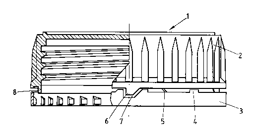
Figure 1 is partly a section and partly an
elevational view of the top according to the invention in a
first embodiment.
Figure 2 is an analogous view related to a first
variant.
Figure 3 is an analogous view related to a second
variant.
Figure 4 is an analogous view related to a third
variant.
-- 2
71224-2

2035079
The screw top 1 shown in these four figures comprises
a skirt 2 and a sealing ring 3.
On the skirt or on the sealing ring can be provided
protective backing elements 4 which prevent that the skirt 2
approaches completely the sealing ring 3 whereby some of the
small cross-elements 5 connecting the sealing ring to the
skirt would break.
All these details, such as the presence of a tooth 6
projecting into a cutout 7 of the sealing ring 2, have been
described in the above-mentioned Luxemburg application.
It is to be noted that the present invention aims at
improving these but also other types of tops provided that
they comprise a skirt, a sealing ring and small cross-elements
connecting these elements together.
In order to avoid that one or more of these small
cross-elements would be broken during mechanical
manipulations, means are provided, according to the present
patent application, which prevent any radial displacement of
the sealing ring 3, i.e. any
- 2a -
71224-2

- 3 2035079
movement towards the in - or the outside of the top.
This object can be reached by different possible,
technical embodiments but it will be clear that some of them ~vill
give problems with respect to the design of the injection moulds.
5Referring to Figure 1, it can be seen that the skirt
2 comprises a prolongation 8 directed towards the sealing ring 3.
When the top and the sealing ring take the position shown in the
figure, i.e. when the small cross-elements aren't broken yet, the
prolongation 8 of the skirt 2 of the top extends sufficiently far so
10as to prevent ai~y radial deformation of the sealing ring. Thereto
it is enough that the prolongation 8 extends a tenth of a millimeter
or some tenths of a millimeter beyond the edge of the sealing ring
which is directed towards the skirt.
A f irst variant of the top according to the invention
15is represented in Figure 2 wherein the prolongation, indicated here
by reference 9, is provided at the outer side of the sealing ring 3.
It's enough that the prolongation 9 extends very slightly beyond the
free edge of the sealing ring 3 to prevent any radial movement of
this sealing ring. In the two cases, the sealing ring keeps perf ectly
20its circular shape and no rupture of the small cross-elements 5 is
to be feared.
The same situation is created by the second variant
shown in Figure 3 wherein it is on the contrary the sealing ring 3
which is provided with a prolongation, indicated by reference 10,
25at the outsider of the part of the top skirt 2 which is directed towards
the sealing ring.
It will be clear that even when the most logical
embodiments consist in providing prolongations 8-10 extending circularly
over the total periphery either of the skirt of the top or of the sealing
30ring, these prolongations could also be provided at some places only.
In a last variant it would also be possible to prolong
all the ribs 11 or some of them. By rib it has to be understood the
vertical projections, the skirt of certain tops present at the outside,
generally with the object to make screwing and unscrewing easier.
35Although several embodiments have been described,

~ 4 ~ 2035079
some of which have to be considered as preferred embodiments from
the point of view of realising pieces which permit the injection of
tops according to the invention, it will be noted that all these embodi-
ments realise the same object which is to prevent any radial movement
of the sealing ring, these movements being the cause of the rupture
of the small cross-elements 5.
In principle, the invention is thus not limited to
the described embodiments and many modifiations could be brought
thereon without leaving the scope of the present Patent Application.

Representative Drawing
A single figure which represents the drawing illustrating the invention.
Administrative Status

2024-08-01:As part of the Next Generation Patents (NGP) transition, the Canadian Patents Database (CPD) now contains a more detailed Event History, which replicates the Event Log of our new back-office solution.

Please note that "Inactive:" events refers to events no longer in use in our new back-office solution.

For a clearer understanding of the status of the application/patent presented on this page, the site Disclaimer , as well as the definitions for Patent , Event History , Maintenance Fee  and Payment History  should be consulted.

Event History

Description Date
Time Limit for Reversal Expired 2009-01-28
Letter Sent 2008-01-28
Inactive: Late MF processed 2003-02-13
Inactive: Late MF processed 2001-03-26
Letter Sent 2001-01-29
Letter Sent 2000-07-26
Inactive: Late MF processed 1999-02-17
Letter Sent 1999-01-28
Grant by Issuance 1995-09-12
Request for Examination Requirements Determined Compliant 1991-10-23
All Requirements for Examination Determined Compliant 1991-10-23
Application Published (Open to Public Inspection) 1991-08-06

Abandonment History

There is no abandonment history.

Fee History

Fee Type Anniversary Year Due Date Paid Date
MF (patent, 7th anniv.) - standard 1998-01-28 1997-12-22
Reversal of deemed expiry 2003-01-28 1999-02-17
MF (patent, 8th anniv.) - standard 1999-01-28 1999-02-17
MF (patent, 9th anniv.) - standard 2000-01-28 1999-12-13
Registration of a document 2000-06-20
Reversal of deemed expiry 2003-01-28 2001-03-26
MF (patent, 10th anniv.) - standard 2001-01-29 2001-03-26
MF (patent, 11th anniv.) - standard 2002-01-28 2002-01-14
MF (patent, 12th anniv.) - standard 2003-01-28 2003-02-13
Reversal of deemed expiry 2003-01-28 2003-02-13
MF (patent, 13th anniv.) - standard 2004-01-28 2003-12-23
MF (patent, 14th anniv.) - standard 2005-01-28 2004-12-22
MF (patent, 15th anniv.) - standard 2006-01-30 2005-12-23
MF (patent, 16th anniv.) - standard 2007-01-29 2006-12-19
Owners on Record

Note: Records showing the ownership history in alphabetical order.

Current Owners on Record
L & M SERVICES B.V.
Past Owners on Record
JEAN DEBETENCOURT
Past Owners that do not appear in the "Owners on Record" listing will appear in other documentation within the application.
Documents

To view selected files, please enter reCAPTCHA code :


To view images, click a link in the Document Description column. To download the documents, select one or more checkboxes in the first column and then click the "Download Selected in PDF format (Zip Archive)" or the "Download Selected as Single PDF" button.

List of published and non-published patent-specific documents on the CPD .

If you have any difficulty accessing content, you can call the Client Service Centre at 1-866-997-1936 or send them an e-mail at CIPO Client Service Centre.


Document
Description 
Date
(yyyy-mm-dd) 
Number of pages   Size of Image (KB) 
Abstract 1994-03-01 1 10
Claims 1994-03-01 1 21
Drawings 1994-03-01 2 45
Description 1994-03-01 4 108
Abstract 1995-09-11 1 13
Description 1995-09-11 5 148
Claims 1995-09-11 1 31
Drawings 1995-09-11 2 46
Representative drawing 1998-07-16 1 10
Maintenance Fee Notice 1999-02-24 1 179
Late Payment Acknowledgement 1999-02-28 1 172
Maintenance Fee Notice 2001-02-25 1 176
Late Payment Acknowledgement 2001-03-29 1 171
Late Payment Acknowledgement 2003-02-19 1 167
Maintenance Fee Notice 2008-03-09 1 172
Fees 1994-10-02 2 60
Fees 2002-01-13 1 37
Fees 1996-12-18 1 239
Fees 1995-12-17 1 50
Fees 1994-12-13 1 66
Fees 1993-12-21 1 39
Fees 1992-12-17 1 33
Prosecution correspondence 1991-01-27 12 516
Examiner Requisition 1994-07-04 3 100
Prosecution correspondence 1995-01-04 2 70
Prosecution correspondence 1995-06-01 1 35
Prosecution correspondence 1995-02-16 1 23
Courtesy - Office Letter 1995-07-13 1 56
Correspondence related to formalities 1995-06-05 1 33
Prosecution correspondence 1991-10-22 1 27
Courtesy - Office Letter 1992-05-12 1 37
Correspondence related to formalities 1991-06-13 1 33
Courtesy - Office Letter 1991-06-04 1 33