Sélection de la langue

Search

Sommaire du brevet 2035079 

Énoncé de désistement de responsabilité concernant l'information provenant de tiers

Une partie des informations de ce site Web a été fournie par des sources externes. Le gouvernement du Canada n'assume aucune responsabilité concernant la précision, l'actualité ou la fiabilité des informations fournies par les sources externes. Les utilisateurs qui désirent employer cette information devraient consulter directement la source des informations. Le contenu fourni par les sources externes n'est pas assujetti aux exigences sur les langues officielles, la protection des renseignements personnels et l'accessibilité.

Disponibilité de l'Abrégé et des Revendications

L'apparition de différences dans le texte et l'image des Revendications et de l'Abrégé dépend du moment auquel le document est publié. Les textes des Revendications et de l'Abrégé sont affichés :

  • lorsque la demande peut être examinée par le public;
  • lorsque le brevet est émis (délivrance).
(12) Brevet: (11) CA 2035079
(54) Titre français: COUVERCLE A VISSER
(54) Titre anglais: SCREW TOP
Statut: Périmé et au-delà du délai pour l’annulation
Données bibliographiques
(51) Classification internationale des brevets (CIB):
  • B65D 41/34 (2006.01)
  • B65D 55/02 (2006.01)
(72) Inventeurs :
  • DEBETENCOURT, JEAN (Belgique)
(73) Titulaires :
  • L & M SERVICES B.V.
(71) Demandeurs :
  • L & M SERVICES B.V.
(74) Agent: SMART & BIGGAR LP
(74) Co-agent:
(45) Délivré: 1995-09-12
(22) Date de dépôt: 1991-01-28
(41) Mise à la disponibilité du public: 1991-08-06
Requête d'examen: 1991-10-23
Licence disponible: S.O.
Cédé au domaine public: S.O.
(25) Langue des documents déposés: Anglais

Traité de coopération en matière de brevets (PCT): Non

(30) Données de priorité de la demande:
Numéro de la demande Pays / territoire Date
90870020.6 (Office Européen des Brevets (OEB)) 1990-02-05

Abrégés

Abrégé anglais


The invention relates to a screw top comprising
essentially two elements formed by a skirt and a sealing ring connected
together in a number of places by means of small cross-elements
which can be broken when unscrewing the top, characterised in that
of said two elements, either the skirt (2) or the sealing ring (3) compri-
ses prolongations (8-10) which extend sufficiently far towards and
beyond the opposite element so as to prevent any deformation of
the sealing ring (3) in the radial direction of the top.

Revendications

Note : Les revendications sont présentées dans la langue officielle dans laquelle elles ont été soumises.


THE EMBODIMENTS OF THE INVENTION IN WHICH AN EXCLUSIVE
PROPERTY OR PRIVILEGE IS CLAIMED ARE DEFINED AS FOLLOWS
1. A screw top having a longitudinal axis comprising:
a skirt disposed about said axis;
a sealing ring disposed about said axis and spaced
from the skirt leaving an axial gap therebetween;
a predetermined number of cross-elements extending
between a lower edge of said skirt and an upper edge of said
sealing ring for being broken when unscrewing the skirt due to
their small section;
prolongation means extending from said lower edge of
said skirt towards and beyond said upper edge of said sealing
ring along an innermost side of said sealing ring for preventing
any deformation of said sealing ring in a radial direction so as
to avoid rupture of said cross-elements.
2. A screw top as claimed in claim 1, wherein said
prolongations extend in a direction substantially parallel to
said longitudinal axis of said top.
3. A screw top as claimed in claim 1, wherein the
prolongation means comprises a plurality of circumferentially
spaced prolongations.

Description

Note : Les descriptions sont présentées dans la langue officielle dans laquelle elles ont été soumises.

-- I, 2035079
SCREW TOP
The present invention relates to a screw top compris-
ing essentially two elements formed by a skirt and a sealing
ring which is in a predetermined number of places connected to
said skirt by means of small cross-elements which can be
broken when unscrewing the top due to their small section.
A top which offers this particularity has been the
subject of the Luxemburg Patent Application No. 87469 of March
8, 1989 in the name of the applicant.
The top described in this patent application has such
a structure that the displacements of the skirt with respect
to the sealing ring according to the geometrical axis of the
top do not cause a too early and thus untimely separation of
these two top elements. The tops of this type, conceived by
the applicant, form thus from this point of view a remarkable
amelioration.
However, it appeared that the sealing ring could
still come loose from the skirt due to shocks transmitted to
these tops during their transfer in distribution machines.
Indeed, the lateral shocks transmitted to these tops can cause
the rupture of some of the small cross-elements to which is
referred to in the preamble.
The present patent application has for its object to
remedy this serious disadvantage, i.e. that which causes that
too many tops to be removed and which requires inspections
which would be preferably avoided.
Therefore this invention seeks to provide a screw top
-- 1 --
~ ~ 71224-2
;. ~

2035079
having a longitudinal axis comprising:
a skirt disposed about said axis;
a sealing ring disposed about said axis and spaced
from the skirt leaving an axial gap therebetween;
a predetermined number of cross-elements extending
between a lower edge of said skirt and an upper edge of said
sealing ring for being broken when unscrewing the skirt due to
their small section;
prolongation means extending from said lower edge of
said skirt towards and beyond said upper edge of said sealing
ring along an innermost side of said sealing ring for
preventing any deformation of said sealing ring in a radial
direction so as to avoid rupture of said cross-elements.
Other details and advantages of the invention will
appear from the following description of a screw top equipped
with a sealing ring according to the invention. This
description is only given by way of example and does not limit
the invention. The reference numerals relate to the annexed
figures.
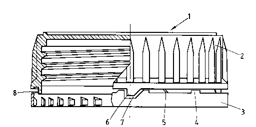
Figure 1 is partly a section and partly an
elevational view of the top according to the invention in a
first embodiment.
Figure 2 is an analogous view related to a first
variant.
Figure 3 is an analogous view related to a second
variant.
Figure 4 is an analogous view related to a third
variant.
-- 2
71224-2

2035079
The screw top 1 shown in these four figures comprises
a skirt 2 and a sealing ring 3.
On the skirt or on the sealing ring can be provided
protective backing elements 4 which prevent that the skirt 2
approaches completely the sealing ring 3 whereby some of the
small cross-elements 5 connecting the sealing ring to the
skirt would break.
All these details, such as the presence of a tooth 6
projecting into a cutout 7 of the sealing ring 2, have been
described in the above-mentioned Luxemburg application.
It is to be noted that the present invention aims at
improving these but also other types of tops provided that
they comprise a skirt, a sealing ring and small cross-elements
connecting these elements together.
In order to avoid that one or more of these small
cross-elements would be broken during mechanical
manipulations, means are provided, according to the present
patent application, which prevent any radial displacement of
the sealing ring 3, i.e. any
- 2a -
71224-2

- 3 2035079
movement towards the in - or the outside of the top.
This object can be reached by different possible,
technical embodiments but it will be clear that some of them ~vill
give problems with respect to the design of the injection moulds.
5Referring to Figure 1, it can be seen that the skirt
2 comprises a prolongation 8 directed towards the sealing ring 3.
When the top and the sealing ring take the position shown in the
figure, i.e. when the small cross-elements aren't broken yet, the
prolongation 8 of the skirt 2 of the top extends sufficiently far so
10as to prevent ai~y radial deformation of the sealing ring. Thereto
it is enough that the prolongation 8 extends a tenth of a millimeter
or some tenths of a millimeter beyond the edge of the sealing ring
which is directed towards the skirt.
A f irst variant of the top according to the invention
15is represented in Figure 2 wherein the prolongation, indicated here
by reference 9, is provided at the outer side of the sealing ring 3.
It's enough that the prolongation 9 extends very slightly beyond the
free edge of the sealing ring 3 to prevent any radial movement of
this sealing ring. In the two cases, the sealing ring keeps perf ectly
20its circular shape and no rupture of the small cross-elements 5 is
to be feared.
The same situation is created by the second variant
shown in Figure 3 wherein it is on the contrary the sealing ring 3
which is provided with a prolongation, indicated by reference 10,
25at the outsider of the part of the top skirt 2 which is directed towards
the sealing ring.
It will be clear that even when the most logical
embodiments consist in providing prolongations 8-10 extending circularly
over the total periphery either of the skirt of the top or of the sealing
30ring, these prolongations could also be provided at some places only.
In a last variant it would also be possible to prolong
all the ribs 11 or some of them. By rib it has to be understood the
vertical projections, the skirt of certain tops present at the outside,
generally with the object to make screwing and unscrewing easier.
35Although several embodiments have been described,

~ 4 ~ 2035079
some of which have to be considered as preferred embodiments from
the point of view of realising pieces which permit the injection of
tops according to the invention, it will be noted that all these embodi-
ments realise the same object which is to prevent any radial movement
of the sealing ring, these movements being the cause of the rupture
of the small cross-elements 5.
In principle, the invention is thus not limited to
the described embodiments and many modifiations could be brought
thereon without leaving the scope of the present Patent Application.

Dessin représentatif
Une figure unique qui représente un dessin illustrant l'invention.
États administratifs

2024-08-01 : Dans le cadre de la transition vers les Brevets de nouvelle génération (BNG), la base de données sur les brevets canadiens (BDBC) contient désormais un Historique d'événement plus détaillé, qui reproduit le Journal des événements de notre nouvelle solution interne.

Veuillez noter que les événements débutant par « Inactive : » se réfèrent à des événements qui ne sont plus utilisés dans notre nouvelle solution interne.

Pour une meilleure compréhension de l'état de la demande ou brevet qui figure sur cette page, la rubrique Mise en garde , et les descriptions de Brevet , Historique d'événement , Taxes périodiques et Historique des paiements devraient être consultées.

Historique d'événement

Description Date
Le délai pour l'annulation est expiré 2009-01-28
Lettre envoyée 2008-01-28
Inactive : TME en retard traitée 2003-02-13
Inactive : TME en retard traitée 2001-03-26
Lettre envoyée 2001-01-29
Lettre envoyée 2000-07-26
Inactive : TME en retard traitée 1999-02-17
Lettre envoyée 1999-01-28
Accordé par délivrance 1995-09-12
Exigences pour une requête d'examen - jugée conforme 1991-10-23
Toutes les exigences pour l'examen - jugée conforme 1991-10-23
Demande publiée (accessible au public) 1991-08-06

Historique d'abandonnement

Il n'y a pas d'historique d'abandonnement

Historique des taxes

Type de taxes Anniversaire Échéance Date payée
TM (brevet, 7e anniv.) - générale 1998-01-28 1997-12-22
Annulation de la péremption réputée 2003-01-28 1999-02-17
TM (brevet, 8e anniv.) - générale 1999-01-28 1999-02-17
TM (brevet, 9e anniv.) - générale 2000-01-28 1999-12-13
Enregistrement d'un document 2000-06-20
Annulation de la péremption réputée 2003-01-28 2001-03-26
TM (brevet, 10e anniv.) - générale 2001-01-29 2001-03-26
TM (brevet, 11e anniv.) - générale 2002-01-28 2002-01-14
TM (brevet, 12e anniv.) - générale 2003-01-28 2003-02-13
Annulation de la péremption réputée 2003-01-28 2003-02-13
TM (brevet, 13e anniv.) - générale 2004-01-28 2003-12-23
TM (brevet, 14e anniv.) - générale 2005-01-28 2004-12-22
TM (brevet, 15e anniv.) - générale 2006-01-30 2005-12-23
TM (brevet, 16e anniv.) - générale 2007-01-29 2006-12-19
Titulaires au dossier

Les titulaires actuels et antérieures au dossier sont affichés en ordre alphabétique.

Titulaires actuels au dossier
L & M SERVICES B.V.
Titulaires antérieures au dossier
JEAN DEBETENCOURT
Les propriétaires antérieurs qui ne figurent pas dans la liste des « Propriétaires au dossier » apparaîtront dans d'autres documents au dossier.
Documents

Pour visionner les fichiers sélectionnés, entrer le code reCAPTCHA :


Pour visualiser une image, cliquer sur un lien dans la colonne description du document. Pour télécharger l'image (les images), cliquer l'une ou plusieurs cases à cocher dans la première colonne et ensuite cliquer sur le bouton "Télécharger sélection en format PDF (archive Zip)" ou le bouton "Télécharger sélection (en un fichier PDF fusionné)".

Liste des documents de brevet publiés et non publiés sur la BDBC .

Si vous avez des difficultés à accéder au contenu, veuillez communiquer avec le Centre de services à la clientèle au 1-866-997-1936, ou envoyer un courriel au Centre de service à la clientèle de l'OPIC.


Description du
Document 
Date
(aaaa-mm-jj) 
Nombre de pages   Taille de l'image (Ko) 
Abrégé 1994-03-01 1 10
Revendications 1994-03-01 1 21
Dessins 1994-03-01 2 45
Description 1994-03-01 4 108
Abrégé 1995-09-11 1 13
Description 1995-09-11 5 148
Revendications 1995-09-11 1 31
Dessins 1995-09-11 2 46
Dessin représentatif 1998-07-16 1 10
Avis concernant la taxe de maintien 1999-02-24 1 179
Quittance d'un paiement en retard 1999-02-28 1 172
Avis concernant la taxe de maintien 2001-02-25 1 176
Quittance d'un paiement en retard 2001-03-29 1 171
Quittance d'un paiement en retard 2003-02-19 1 167
Avis concernant la taxe de maintien 2008-03-09 1 172
Taxes 1994-10-02 2 60
Taxes 2002-01-13 1 37
Taxes 1996-12-18 1 239
Taxes 1995-12-17 1 50
Taxes 1994-12-13 1 66
Taxes 1993-12-21 1 39
Taxes 1992-12-17 1 33
Correspondance de la poursuite 1991-01-27 12 516
Demande de l'examinateur 1994-07-04 3 100
Correspondance de la poursuite 1995-01-04 2 70
Correspondance de la poursuite 1995-06-01 1 35
Correspondance de la poursuite 1995-02-16 1 23
Courtoisie - Lettre du bureau 1995-07-13 1 56
Correspondance reliée aux formalités 1995-06-05 1 33
Correspondance de la poursuite 1991-10-22 1 27
Courtoisie - Lettre du bureau 1992-05-12 1 37
Correspondance reliée aux formalités 1991-06-13 1 33
Courtoisie - Lettre du bureau 1991-06-04 1 33