Note: Descriptions are shown in the official language in which they were submitted.
2~3~
The invention relates to an arrangement for installing and
removing a lance, in particular a measuring and/or
sampling lance, into and from a titable metallurgical
vessel, in particular a steel works converter, wherein the
lance is designed as a guide and is guided by a drive
stationarily arranged in the direction of the axis of the
lance and is movable in the direction of its axis, the
drive being mounted so as to be pivotable.
Installations for installing and removing a lance have
been known from DE-C-27 38291 and EP-A-0 079 290. With
these two known installations, the lance is insertable
into the metallurgical vessel through an opening
especially provided for this purpose in the wall of the
metallurgical vessel, the lance being mounted with its
upper end at a lance carriage that is movable along rails
arranged beside the converter, the length of the rails
corresponding to the length of the lance.
For alignment of the lance with the opening in the side
wall of the metallurgical vessel, the guide for the lance
carriage is displaceable or tiltable relative to the
metallurgical vessel. This requires complex means, because
the guide for the lance carriage is heavy due to its
great length and must be built accordingly stable to avoid
oscillations of the lance. The guide for the lance
carriage and its support on the carrying structure of the
steel works hall requires a considerable amount of space
~Q3~2~
laterally of the converter, which makes other
manipulations, such as slipping a probe onto the lance or
taking it off the lance, difficult to carry out.
Movement of the known lance carriages along their
guides is effected by means of rope winches or chain
hoists. This involves the danger of a rope or chain break
causing damage to lance and metallurgical vessel.
An installation of the initially defined kind is known
from US-A-4,637,592. In this installation, an arrangement
for retaining slag is pivotable into a converter and
installable in a tap hole from within the converter
interior. The arrangement is fastened to the end of a
lance, and the lance is displaceably inserted in a sleeve
that is provided with a drive. The sleeve in turn is
pivotably mounted on a stationary supporting structure.
Wlth this known installation difficulties may arise if
the tap hole of the matallurgical vessel does not always
Assume the same position after tilting of the vessel,
such as occurs due to tooth flank play or after a certain
wear of a tilting drive tilting the metallurgical vessel
and provided with toothed wheels.
The invention aims at avoiding these disadvantages and
difficulties and has as its object to design an
installation of the initially defined kind such that it
requires only little space and is very safe to operate.
Despite a simple construction, the installation is to be
'~3~2~
particularly stable. In particular, the inatallation iB to
enable a precise adjustment of the lance position relative
to the metallurgical vessel with inexpensive means of
simple construction, even in case the metallurgical vessel
does not always assume exactly the same position after a
tilting procedure.
According to the invention, this object is achieved in
that the drive is mounted 60 as to be pivotable about two
axes crossing each other.
According to a preferred embodiment, the drive is
designed as a frictional wheel drive. This guarantees a
problem-free movement of the lance in the axial direction,
this being so even if the lance is contaminated. Should a
failure still occur, e.g. due to an accumulation of slag,
the frictional wheel drive, which constitutes a kind of
safety slidlng clutch, is not negatively affected, and
after release of the frictional engagement of the drive
wheels, the lance can be pulled out of the metallurgical
vessel, e.g. by means of a crane. After cleaning of the
lance the installation is immediately ready for use.
Another preferred embodiment is characterised in that
the drive is movable, preferably in the direction
perpendicular to the axis of the lance, approximately in
the horizontal direction. The displaceability also serves
for adapting the position of the lance axis to the opening
of the metallurgical vessel. Furthermore, it may serve to
~3f~2~1
bring a further lance, arranged beside the measuring
lance, for a second sampling or second ~ea~urement in
alignment with the opening of the metallurgical vessel, or
it may also serve to push a clearing device through the
opening of the metallurgical vessel prior to effecting the
measurement or sampling, to thereby clean t~e opening from
slag or other deposits, so that no damage can occur at
the probes slipped onto the free end of the lances when
effecting the measurement or sampling. Displaceability of
the drive may also be advantageous if the lance is to be
introduced into differently arranged openings of the same
metallurgical vessel or is to be introduced into different
metallurgical vessels.
Preferably, a further drive for a further device
insert~ble into the metallurgical vessel, such as a
cleaning means, i8 provided beside the drive for the lance
for this purpose.
For ensuring a perfect operation of the lance in the
rough steel works operation, the drive is suitably
surrounded by a housing, at whose passage opening facing
the metallurgical vessel and provided for the lance or, if
a further device is present, for that device, a scraping
means for cleaning the lance or the further device is
provided.
A preferred, particularly sturdy variant is
characterised in that horizontally extending rails are
2~3~ 2~
provided on a stationary supporting structure, along which
a carrying plate is displaceably guided, a base plate
being mounted to the carrying plate so as to be pivotable
about an axis extending perpendicular to the carrying
plate, on which base plate at least one housing
accommodating a drive for the lance or in case of the
presence of a further device, a drive for the further
device is mounted so as to be pivotable about an axis
oriented parallel to the guide rails, a displacement means
for moving the carrying plate relative to the stationary
supporting structure, a pivot means for pivoting the base
plate relative to the carrying plate, and a further pivot
means for pivoting the housing relative to the base plate
being provided.
To avoid falling down of the lance in case of a failure
of the drive, advantageously a braking means is provided
in the housing for braking and fixing the lance, or in
case of the presence of a further device, for braking and
fixing the further device relative to the housing.
Advantageously, the lance is designed to be hollow, and
the cavity of the lance is connected to a gas supply duct.
According to a preferred embodiment, in the interior of
the hollow lance there is further provided a protecting
tube for measuring cables arranged in the interior of the
lance, the protecting tube suitably being connected to a
gas supply duct.
A preferred structure is characterised in that the
~3'~2~
frictional wheel drive is formed by two pairs of
frictional wheels, wherein one pair of frictional wheels
each supports the lance at two opposing sides and at least
one frictional wheel of a pair of frictional wheels is
drivable and this frictional wheel and/or the oppositely
arranged frictional wheel of this pair of frictional
wheels is pressable against the lance.
Advantageously, the frictional wheel drive is formed by
at least three frictional wheels, at least one of which is
drivable and at least one is pressable against the lance.
A method of positioning a lance relative to an opening
of a tiltable metallurgical vessel, in particular a steel
works converter, is characterised in that the actual
position of the metallurgical vessel is sensed by means of
a position transmitter arranged on the vessel and a drive
means is actuated for positioning the lance in dependence
on the sensed actual position.
Suitably, the position of the lance is determined by
position sensors, i.e. by a distance sensor determining
the position of the carrying plate, an angle sensor
determining the angular position of the base plate
relative to the carrying plate, and an angle sensor
determining the angular position of the housing relative
to the base plate, and the values of the position
transmitter of the metallurgical vessel are fed to a
calcLlator, and the latter controls the drive means for
i
J
'~ ~ 3 ~
the lance, i.e. the displacement means, the pivot means
and the further pivot means, i.e. until the position
sensors allocated to the lance indicate the coinc~dence of
the position of the lance and the position of the opening
of the metallurgical vessel.
The invention will now be explained in more deta l by
way of the accompanying drawings and an exemplary
embodiment, wherein
Fig. 1 is a side view of the installation according to the
invention with the lance in the retracted position, and
Fig. 2 is a partially sectioned view in the direction of
the arrow II of Fig. 1.
Fig. 3 is a schematic illustration of a variant of the
lance drive.
Fig. 4 is a schematic illustration of a method of
positioning a lance.
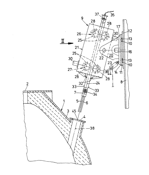
In the drawings, a steel works converter 1 is
illustrated in section, the plane of the section extending
through the longitudinal axis of the converter and its
tilting axis. The mouth of the converter is denoted by 2.
During tilting of the converter 1 it can be moved along a
circular arc, perpendicular to the plane of drawing or
section.
In the wall 3 of the converter 1, a passage opening 4
for introducing a lance 7 equipped with a measuring 5
and/or sampling probe 6 is provided in the vicinity of the
3~ 27
mouth 2. The lance 7 may also be designed as a supply
means for charging additives. An installation 9 serves for
introducing and removing the lance 7, which installation
is arranged on a stationary supporting structure, e.g. a
hall structure 8, and is designed as follows:
On the supporting structure 6 there are provided
stationary, approximately horizontally extending rails 10,
wich, in the exemplary embodiment illustrated, are
designed as dovetail-shaped grooves. These grooves 10 are
provided in a supporting plate 11, which is mounted on the
hall structure via an understructure 12. A carrying plate
14, which is provided with dovetail-shaped guide ledges 13
on its rear side is displaceable along the grooves 10, the
guide ledges 13 protruding into the grooves 10. A pressure
medium cylinder 15 mounted on the carrying plate 14, on
the one hand, and on the understructure 12, on the other
hand, serves for displacement.
On the carrying plate 14 a pivot pin 16 directed
perpendicular thereto i5 provided. On this pivot piD 16 a
base plate 17 arranged parallel to the carrying plate is
pivotably mounted. As the pivot drive, a pressure medium
cylinder 18 is provided, which is hinged to a projection
19 of the base plate 17 , on the one hand, and to the
carrying plate 14, on the other hand. The base plate 17 is
equipped with two spaced apart and parallel brMckets 20
extending approximately perpendicular to the base pl~te 17
2~3~
towards the front. Between these brackets 20, a housing 21
is inserted and pivotably mounted on the brackets 20 via
pivot pins 22. ~ere, too, a pressure medium cylinder 23 is
provided as the pivot drive for the housing 21, which
pressure medium cylinder is hinged to the base plate 17,
on the one hand, and to the housing 21, on the other hand.
The axis of the pivot pins 22 and the axis of the pivot
pin 16 need not intersect; they may also cross at a
distance from each other, i.e. be skew to each other.
According to the exemplary embodiment illustrated, the
housing 21 is designed in two parts, two wheel pairs 26,
27, spaced apart in the direction of the longitudinal axis
24 of the lance 7 and formed by frictional wheels 25 being
provided in each part of the housing 21. The frictional
wheels 25 are designed with lateral guiding beads 28. The
frlctional wheels 25 of a first part of the housing 21 are
ln frictional engagement with a lance 7, the frictional
wheels 25 provided in the other part of the housing 21 are
in frictional engagement with a clearing device 29
provided for cleaning the passage opening 4 of the
converter 1 before sampling or measuring are effected, so
that the sampling 6 or measuring probe S provided on the
lance 7 are not damaged during their introduction into the
converter 1.
Bach pair 26, 27 of frictional wheels has a frictional
wheel 25 drivable by means of a motor 30 and a frictional
wheel 25 pressable against the second frictional wheel
25, e.g. by mean6 of springs, so that the lance 7 and the
clearing device 29 are each securely held and ~oved by
both pairs 26, 27 of frictional wheelq.
As can be seen from Fig. 1, the motors 30 for driving
the frictional wheels are arranged relative to the center
of the housing 21 such that the weight of the housing 21
is as balanced as possible. In the interior of the housing
21 there are braking jaws 31 for securing the lance and
the clearing device 29, in case of an operational stand-
stlll. All the drives for displacing and pivoting the
housing 21 and the motors for driving the frictional
wheels or the brakes may be set into operation either
electro-mechanically or by means of a pressure medium.
As can be seen from Fig. 3, also three frictional
wheels 25' may be provided instead of the two above-
described pairs of frictional wheels. However, the drive
may also be effected by means of a toothed wheel engaging
into a toothed rack provided at a side of the lance 7.
On the lower front side of the housing 21 there are
slag scraping means 32, which clean the sides 33 of the
lance 7 and the clearing device 29 getting into contact
with the frictional wheels 25 at least to such an extent
that perfect frictional engagement with the frictional
wheels 25 without impairing the movement of the lance 7
and of the clearing device 29 is safeguarded.
The lance 7 itself is formed by a hollow square,
multiple-cornered or round steel tube. At the tip of the
lance there are receiving attachments for the measuring 5
or sampling probes 6, the number of the attachments
depending on the type of operation desired, al~o several
measurements or samplings being simultaneously feasible.
At the center of the lance 7 a protecting tube 34 for
measuring cables 35 is provided. Both, the protecting tube
34 and the lance 7 itself may be flushed with flush gas,
e.g. nitrogen, for which purpose the gas supply ducts 36,
37 provided on the upper end of ths lance 7 serve. By
flushing the protecting tube 34, the contacts between the
measuring cables 35 and the probe may be kept clean. The
lance 7itself i8 flushed witha larger amount of gas only
during movement into the converter, so as to cool the
lance.
On account of the housing 21 being displaceable and
pivotable, an exact adaptation of the axis 24 of the lance
7 to the axis 38 of the passage openlng 4 is feaslble, so
that the introduction and removal of the lance 7 or of the
clearing device 29, respectively, may occur without any
problems. This is particularly important if the
metallurgical vessel 1 is tiltable, as in the exemplary
embodiment illustrated. Because of the tilting drive
provided for tilting and equipped with toothed wheels, the
~3~ 27
position of a met~llurgical vessel 1 intended for carrying
out the measurement cannot be exactly determined. This is
due to the tooth flank plays and also to a we~r of the
toothed wheels. The arrangement furthermore makes it
possible to reach any desired point within a certain area
with the lance tip or with the tip of the clearing device
29, respectively.
In addition to an exact adaptation of the lance axis 24
to the axis 38 of the passage opening 4, the arrangement
of the invention may furthermore be used to reach various
passage openings 4 at a metallurgical vessel 1 with one
and the same lance 7, or to carry out measurements at
several adjacently arranged metallurgical vessels 1 with
one and the same lance 7.
The light and compact construction due to the omission
of a separate lance guide extending over the length of the
lance is a particular advantage of the arrangement of the
inventlon. The arrangement of the invention offers a high
operational safety, because it is neither possible for a
rope to tear or slacken, nor for a chain to break.
Furthermore, lance adjustment~ may be effected within a
short span of time, since only short adjustment paths need
be passed and, compared to the prior art, only slight
masses need be moved.
The arrangement according to the invention is op0rated
as follows:
2~3~
The lance 7 can be brought into a ready position, an
exchange position as well as a measurinq position. The
ready position is the starting position for reaching the
exchange position and the measuring position. In the
exchange position, the probe 5, 6 is either automatically
or manually exchanged. The three positions can be reached
by pressing a button on the control panel.
The control panel includes a button for starting the
measurement. If that button is pushed, at first the
clearing device 29 is lowered into the passage opening 4
to clean the same from slag residues. Subsequently the
clearing device 29 is moved back into its initial
position, and the carrying plate 14 is moved until the
lance 7 can be lowered through the passage opening 4 into
the converter. ~hen the measurement has been effected, the
lance 7 returns into the ready position.
Fig. 4 shows an arrangement as illustrated in Figs. 1
and 2, wherein this arrangement i~, however, equipped with
additional installations enabling an automatic adaptation
of the position of the lance 7 relative to the passage
opening 4 of the converter 1. To this end, the converter 1
is equipped with a position transmitter 39 enabling the
exact determination of the tilting position of the
converter 1, i.e. independently of the tooth flank play of
the converter drive. The position transmitter 39 may,
e.g., be fixedly mounted on the trunnion 40 of the
~3~ ~7
converter 1. The value of the position transmitter i5 fed
to a calculator 41. With this position transmitter 39,
which is designed as an angle sensor, it is thus also
possible to determine the position of the axis 38 of the
passage opening 4 passing the wall 3 of the converter 1.
Fig. 4 is a schematic and very exaggerated illustration
of a deviation of the actual position A of the converter
from the vertical set position B, which deviation is
caused by a tooth flank play of the converter drive.
According to Fig. 4, there are further provided position
sensors 42, 43, 44 determining the position of the lance
7, i.e. a distance sensor 42 determining the position of
the carrying plate 14, an angle sensor 43 determining the
angular position of the base plate 17 relative to the
carrying plate 14, and a further angle sensor 44
determining the angular position of the housing 21
relative to the base plate 17. These position sensors 42,
43, 44 suitably are arranged on the drive means lS, lB and
23 provided for positioning the lance 7. The values sensed
by these position sensors 42, 43, 44 are also fed to the
calculator 41. This calculator determines those set values
which the position sensors 42, 43, 44 must indicate in
order that the position of the lance 7 is best adjusted to
the position of the passage opening 4, i.e. on the basis
of the value determined by the position transmitter 39
which takes up the actual position A of the converter 1.
2 ~ 2 ~
Based on the calculated set values, which the po~ition
sensors must indicate, the calculator 41 emits control
signals for the drive means 15, 18 and 23 until these set
v~lues have been reached. Subsequently introduction of the
measuring or sampling lance 7 into the passage opening 4
may be started. If the geometric connections prevent an
alignment of the axis 38 of the passage opening 4 with the
axis 24 of the lance 7, it suffices to direct - by means
of the calculator - the axis 24 of the lance 7 to the
center 45 of the entry cross-section of the passage
opening 4.