Note: Descriptions are shown in the official language in which they were submitted.
,~ 1
2~3521 3 27879-49
TITLE OF THE lNv~N-lION
MODEM HAVING SPEED NOTIFYING MEANS
BACKGROUND OF THE lNv~NllON
The present invention generally relates to modems, and
more particularly to a modem which has a speed notifying means and
a data compression function ~o as to optimize the communication
speed between modems.
In data communication using a telephone switching
network which has a limit to the communication speed between
modems, there is an increasing demand to further improve the
communication speed due to the popular use of terminal equipment
such as personal computers which make data communication via the
telephone switching network.
As one method of meeting the above demand, there is a
proposed modem which has a data compression function and
modulating and demodulating functions. In other words, the
proposed modem compresses the data transmitted from the terminal
equipment and improves the effective throughput of the data
communication between the terminal equipment to several times the
communication speed which is determined by the modulation
technique used between the modems. The value which is multiplied
by the communication speed is referred to as a compression rate.
In the case of the communication between the terminal
equipment using the modems described above, the communi~ation
speed between the terminal equipment and the modem can in
principle be increased to a value which is a product of the
compression rate and the speed determined by the modulation
technique used between the modems or greater. As a result, it
~..
, ~ 2 2 ~ 3 5 2 1 3 27879-49
becomes possible to effectively utilize the effects of the data
compression function of the modems, and the realization of such a
system is awaited.
BRIEF DESCRIPTION ~F THE DRAWINGS
Figure 1 is a system block diagram showing an example of
a conventional modem together with associated terminal equipments
and the like;
Figure 2 is a system block diagram for explaining an
operating principle of a modem according to the present invention;
Figure 3 is a system block diagram showing a first
embodiment of the modem according to the present invention;
Figure 4 is a time chart for explaining the operation of
the first embodiment shown in Figure 3;
Figure 5 is a flow chart for explaining the operation of
the first embodiment shown in Figure 3; and
Figure 6 is a system block diagram showing a second
embodiment of the modem according to the present invention.
Figure 1 shows an example of a conventional modem
together with associated terminal equipment and the like. In
Figure 1, modems 10 and 20 are coupled via a transmission line,
and a terminal equipment 1 is coupled to the modem 10 while a
terminal equipment 5 is coupled to the modem 20. For the sake of
convenience, only the construction of the modem 10 is shown and
described because the construction of modem 20 is the same as that
of the modem 10.
The modem 10 includes a data transmission and reception
part 30, a data compression and decompression part 40, a modem
part 50, and a speed determining part 60. The data transmission
._
~ 20352 1 3
3 27879-49
and reception part 30 performs data transmission and reception
between the modem 10 and the terminal equipment 1. The modem part
50 modulates a transmission signal with a predetermined modulation
technique before transmitting the same to the modem 20, and
demodulates a reception signal which is received from the modem
20. The data compression and decompression part 40 is provided
between the data transmission and reception part 30 and the modem
part 50. The data compression and decompression part 40
compresses the data from the data transmission and reception part
30 at a predetermined compression rate before supplying the same
to the modem part 50, and decompresses the compressed data from
the modem part 50 before supplying the same to the data
transmission and reception part 30. The speed determining part 60
is notified of the speed of the reception signal from the modem
part 50 and sets the communication speed between the data
transmission and reception part 30 and the terminal equipment 1.
Hence, the modem 10 notifies the terminal equipment 1 of
the communication speed which is determined by the modulation
technique used between the modems 10 and 20, regardless of the
data compression technique which is determined when the modems 10
and 20 are connected. In this case, when the communication speed
of the terminal equipment 1 is assumed to be the communication
speed which is notified from the modem 10, the terminal equipment
1 and 5 communicate at the communication speed which is determined
by the modulation technique used between the modems 10 and 20, and
it is impossible to bring out the effects obtainable based on the
data compression function of the modem 10.
In order to bring out the effects of the data
20352 1 3
4 27879-49
compression function of the modem 10 in Figure 1, the
communication speed between the terminal equipment 1 and the modem
10 must be set in advance to a fixed value which is greater than
or equal to a specific value. This specific value is a product of
the communication speed between the modems 10 and 20 which is
determined by the predicted modulation technique used between the
modems 10 and 20 an the data compression rate which is determined
by the predicted data compression technique used between the
modems 10 and 20.
According to the conventional system shown in Figure 1,
it is impossible to obtain the effects of the data compression
even though the modems 10 and 20 have the data compression
function if the terminal equipment 1 and 5 are designed to merely
determine the communication speed between the respective modems 10
and 20 depending on the communication speed notified from the
respective modems 10 and 20.
As described above, in order for the terminal equipment
to effectively utilize the built-in data compression function of
the modem when making the communication through the modem, the
communication speed between the terminal equipment and the modem
muæt be fixed in advance to a speed which takes into account the
predicted effects of the data compression.
On the other hand, there is a proposed modem which
notifies the terminal equipment of the communication speed which
is established by the handshaking between the modems when the
modems are connected, and thereafter changes the communication
speed between the modem and the terminal equipment to the notified
communication speed. For example, a modem employing the AT
~,
2 0 3 5 ~ 1 3 2787g-49
command proposed by Hayes Microcomputer Products, Inc. of the
United States is such a proposed modem. By the appearance of such
a proposed modem, there are now proposed systems in which the
terminal equipment has the functions of changing the communication
speed between the terminal equipment and the modem to the
communication speed which is notified from the modem and
thereafter making the data communication between the terminal
equipment and the modem.
However, even when the terminal equipment which
determines the communication speed between the terminal equipment
and the modem depending on the communication speed notified from
the modem is simply connected to the modem which has the built-in
data compression function, it is impossible to bring out the
effects of the data compression.
SUMMARY OF THE lNv~N,ION
Accordingly, it is a general object of the present
invention to provide a novel and useful modem in which the
problems described above are eliminated.
According to a broad aspect, the present invention
provides a modem which is connectable to terminal equipment and
for communicating with an other modem via a transmission line, the
other modem connectable to other terminal equipment, said modem
comprising:
data transmission and reception means connectable to the
terminal equipment for performing data transmission and reception
with the terminal equipment using a transmission signal;
modem means, connectable to the transmission line, for
determining a modulation technique used between said modem and the
. 6 2 0 3 5 213 27879-49
other modem by handshaking, for modulating the transmission signal
using the modulation technique producing a modulated transmission
signal, for transmitting the modulated transmission signal to the
other modem, for demodulating a modulated reception signal which
is received from the other modem and for outputting a reception
signal and a communication speed determined from the modulation
technique;
data compression and decompression means, coupled between
said data transmission and reception means and said modem means,
for determining a compression technique used between said modem
and the other modem by negotiation, for compressing data from said
data transmission and reception means at a compression rate
determined from the compression technique, for supplying the
transmission signal received from said data transmission and
re~eption part to said modem means, for decompressing the
reception signal received from æaid modem means forming
decompressed data, for supplying the decompressed data to said
data transmission and reception means and for outputting the
compression rate; and
speed determining means, coupled to said modem means, said
data compression and decompression means and said data
transmission and reception means, for determining an optimum
communication speed between said modem and the terminal equipment
in response to the communication speed output from said modem
means and the compression rate output from said data compression
and decompression means, the optimum communication speed being
determined when a communication between said modem and the other
modem is established, and when the demodulation and the data
20352 1 3
7 27879-49
compression techniques are determined and said speed determining
means for notifying the data transmission and reception means of
the optimum communication speed, and
said data transmission and reception means changing a speed
of the data transmission and reception with the terminal equipment
producing a data communication between the terminal equipment and
the other terminal equipment using the optimum communication
speed.
According to the modem of the present invention, it is
possible to bring out effects of the data compreæsion with respect
to the terminal equipment which determines the communication speed
between the terminal equipment and the modem depending on the
communication speed notified from the modem.
In one embodiment of the present invention the data
transmission and reception means performs the data transmission
and reception with the terminal equipment using the optimum
communication speed which is determined based on the communication
speed between the modem and the other modem when no data
compression is performed in the data compression and decompression
means.
In another embodiment of the present invention the data
transmission and reception means performs the data transmission
and reception with the terminal equipment using the optimum
communication speed which is determined based on the data
compression rate producing the optimum communication speed being
greater than or equal to a maximum throughput between the terminal
equipment and the other terminal equipment when data compression
is performed in the data compression and decompression means.
2035? ~ ~
8 27879-49
In another embodiment of the present invention the speed
determining means operates at a mode comprising first and second
modes, and
the modem further comprises selecting means coupled to the
data transmission and reception means and the data compression and
decompression means for selecting the mode of the speed
determining means as one of the first and second modes,
the speed determining means in the first mode notifying the
data transmission and re~eption means of the optimum communication
speed which is determined based on the communication speed between
the modem and the other modem when either no data compression i5
performed or when data compression is performed in the data
compression and decompression means, and
the speed determining means in the second mode notifying the
data transmission and reception means of the optimum communication
speed which is determined based on the data compression rate,
producing the optimum communication speed being greater than or
equal to a maximum throughput between the terminal equipment and
the other terminal equipment when the data compression is
performed in the data compression and decompression means.
According to the modem of the present invention, it is
possible to prevent the communication speed between the terminal
equipment and the modem from being changed to a communication
speed which exceeds the communication capacity of the terminal
equipment when the terminal equipment has a limited operation
speed even if the data compression is made.
According to another aspect, the present invention
provides a speed adapter apparatus for changing a communication
-
9 2 0 3 5 2 7 3 27879-4g
speed of a communicatlon having compressed data between a modem
and termlnal equipment based on a compressed communication
between the modem and another modem, said speed adapter appara-
tus comprising:
detecting means for determining a modem communication
speed and a compression rate used between the modem and the
other modem;
speed determining means for determining an optimum
communicatlon speed based on the modem communication speed and
the compression rate received from said detecting means when the
communication between the modem and the other modem ls esta-
blished; and
speed setting means for setting the communication
speed in each of the modem and the terminal equipment to the
optimum communication speed.
Other ob~ects and further features of the present
inventlon will be apparent form the following detailed
description when read in con~unction with the accompanying
drawings.
DES~RIPTION OF THE PREFERRED EMBODIMENTS
First, a descriptlon will be given of an operating
principle of a modem according to the present invention, by
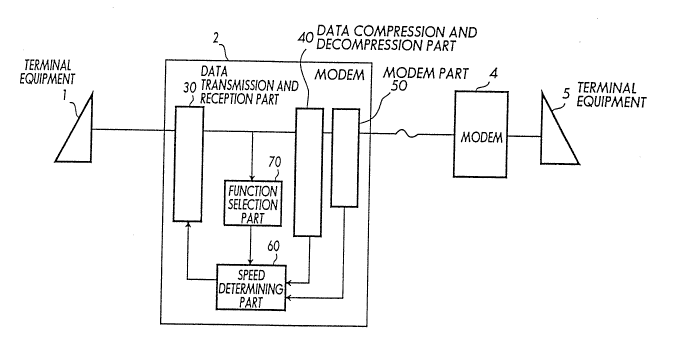
referring to Figure 2. In Figure 2, modems 2 and 4 are coupled
via a transmission line, and a terminal equipment 1 is coupled
to the modem 2 while a terminal equipment 5 is coupled to the
modem 4. For the sake of convenience, only the construction of
the modem 2 is shown and described because the construction of
the modem 4 is the same as that of the modem 2.
9a 20352 1 3 27879-49
When no data compression is made as a result of the
exchange of the control information upon connection of the
modems 2 and 4, the modem 2 notifies the terminal equipment 1 of
the communication speed which is determined by the modulation
lo 2 0 3 5 2 1 3 27879-49
technique which is used between the modems 2 and 4. On the other
hand, when the data compression is made as a result of the
exchange of the control information upon connection of the modems
2 and 4, the modem 2 notifies the terminal equipment 1 of the
communi~ation speed which is greater than or equal to the maximum
throughput between the terminal equipments 1 and 5 determined by
the data compression technique used. In addition, the
communication speed on the line between the modem 2 and the
terminal equipment 1 is changed to the above described
communication speed which is notified to the terminal equipment 1.
The modem 2 includes a data transmission and reception
part 30, a data compression and decompression part 40, a modem
part 50, a speed determining part 60 and a function selection part
70. The data transmission and reception part 30 makes data
transmission and reception between the modem 10 and the terminal
equipment 1. The modem part 50 modulates a transmission signal
with a predetermined modulation techni~ue before transmitting the
same to the modem 4, and demodulates a reception signal which is
received from the modem 4. The data compression and decompression
part 40 is provided between the data transmission and reception
part 30 and the modem part 50. The data compression and
decompression part 40 compresses the serial data from the data
transmission and reception part 30 at a predetermined compression
rate before supplying the same to the modem part 50, and
decompresses the compressed serial data from the modem part 50
before supplying the same to the data transmission and reception
part 30. When the connection between the modems 2 and 4 is
established, the modulation technique in the modem part 50 is
11 2 0 3 5 2 ~ 3 27879-49
determined and the data compression technique of the data
compression and decompression part 40 is determined, the speed
determining part 60 is notified of the communication speed between
the modems 2 and 4 determined from the modulation technique as
well as the compression rate determined from the data compression
technique, and determines the optimum communication speed.
Furthermore, when the data compression is made as a
result of the exchange of the control information upon connection
of the modems 2 and 4, the modem 2 notifies the terminal equipment
1 of the communication speed which is greater than or equal to the
maximum throughput between the terminal equipments 1 and 5
determined by the data compression technique employed, or the
communication speed which is determined by the modulation
technique used between the modems 2 and 4, depending on the
control character from the terminal equipment 1 or hardware strap,
that is, the hardware setting made by a dip switch or the like.
The functions of the parts 30, 40, 50, 60 and 70 of the
modem 2 may be realized by a combination of hardware and software
or solely by software.
The modem 2 is coupled to the terminal equipment 1 via
the data transmission and reception part 30, and is coupled to the
terminal equipment 5 via the modem part 50 the modem 4 and the
transmission line. Hence, a communication can be made between the
terminal equipment 1 and 5.
When the connection between the modems 2 and 4 is
established, modulation technique used between the modems 2 and 4
is determined by the modem part 50 and the data compression
technique used in each of the modems 2 and 4 is determined by the
12 2 0 3 5 2 1 3 27879-49
data compression and decompression part 40. Because the
communication speed between the modems 2 and 4 determined by the
modulation technique and the data compression rate determined by
the data compression technique are notified to the speed
determining part 60, the optimum communication speed which takes
into account the data compression rate is determined by the speed
determining part 60.
The communication speed which is determined by the speed
determining part 60 is notified to the terminal equipment 1 via
the data transmission and reception part 30. Then, the data
transmission and reception part 30 changes the communication speed
between the modem 2 and the terminal equipment 1 to the
communication speed which is notified from the speed determining
part 60.
If the terminal equipment 1 changes the communication
speed to the communication speed notified from the modem 2 and the
communication speed between the modem 4 and the terminal equipment
5 is set to an optimum communication speed which takes into
account the data compression rate, the communication between the
terminal equipments 1 and 5 can thereafter be made with the
throughput value which effectively brings out the effects of the
data compression function.
In addition, because the function selecting part 70 is
provided in the modem 2, it is possible to selectively activate or
deactivate the function of optimizing the communication speed
depending on whether or not the data compression is made between
the modems 2 and 4. Accordingly, in the case where the
communication capacity of the terminal equipment 1 is limited, it
A
.
13 2 0 3 5 2 ~ 3 27879-49
is possible to prevent the communication speed from being changed
to a communication speed exceeding the communication capacity of
the terminal equipment 1 by optimizing the communication speed
depending on whether or not the data compression is made. The
setting of the function selecting part 70 may be made by the
control character from the terminal equipment 1 or by the hardware
strap, that is, the hardware setting such as the setting of the
dip switch.
Next, a description will be given of a first embodiment
of the modem according to the present invention, by referring to
Figure 3. In Figure 3, those parts which are the same as those
corresponding parts in Figure 2 are designated by the same
reference numeralæ.
In Figure 3, the modems 2 and 4 are coupled via a
telephone switching network 3, and the terminal equipment 1 is
coupled to the modem 2 while the terminal equipment 5 is coupled
to the modem 4. The modems 2 and 4 respectively have the data
compression and decompression function as well as the modem
function. Because the construction of the modem 4 is the same as
that of the modem 2, only the construction of the modem 2 is shown
in Figure 3 and described hereunder.
The modem 2 shown in Figure 3 includes a data
compression and decompression function as well as a modulation and
demodulation function, similarly as in the case of the
conventional modem 10 described above in Figure 1. The modem 2
includes a serial input/output controller (SIO) 21, a data
compression/decompression controller (CMP) 22, a
modulation/demodulation controller (MOD) 23, a message controller
14 2 0 3 5 2 1 3 27879-49
(MSG) 24, a character distinguishability controller (DIS) 25, a
data rate decision controller (DEC) 26, and a data rate setting
controller (SET) 27.
Figure 4 is a time chart for explaining the exchange of
signals in the embodiment shown in Figure 3.
When a call out signal ATD (DN) including a telephone
number DN assigned to the terminal equipment 1 is transmitted from
the terminal equipment 5 to the modem 4 in order to connect the
terminal equipments 1 and 5, the modem 4 makes a call out to the
telephone switching network (TSN) 3 and sends the telephone number
DN.
The TSN 3 which receives the telephone number DN selects
the terminal equipment 1 by a known means and transmits a calling
signal to the modem 2.
The modem 2 which receives the calling signal sends a
signal having a logic value "1" to a signal line CI with a
procedure in conformance with the CCITT Recommendations V.24.
Hence, when an answer signal ATA is returned from the terminal
equipment 1 to the modem 2, a handshaking is made between the
modems 2 and 4 via the TSN 3 for determining the modulation
technique based on the CCITT Recommendations V Series.
Next, a negotiation for determining the data compression
technique, that is, exchange of control information, is made
between the modems 2 and 4 and the data compression technique is
determined. This process is in conformance with the CCITT
Recommendations V.42 bi~.
The MOD 23 of the modem 2 notifies the DEC 26 of the
communication speed which is determined from the modulation
s 20352 1 3
15 27879-49
technique used between the modems 2 and 4, and the CMP 22 notifies
the DEC 26 of the data compression technique between the modems 2
and 4. In this embodiment, the above communication speed is 2400
bps and the data compression rate becomes doubled at the maximum
by the above data compression technique.
Because the data compression rate is "2" in this
embodiment, the DEC 26 determines or sets the serial port speed to
4800 bps and notifies or sends this communication speed to the MSG
24. The MSG 24 assembles this communication speed value in a
predetermined character sequence to the terminal equipment 1, and
notifies this communication speed value to the terminal equipment
1 via the SI0 21.
After the communication speed value is notified to the
terminal equipment 1, the DEC 26 notifies the SET 27 of the
determined communication speed. The SET 27 changes the
communication speed of the SI0 21 to the notified speed.
The terminal equipment 1 makes the data communication
with the modem 2 at the communication speed notified from the
modem 2. Accordingly, if the communication speed between the
terminal equipments 1 and 5 is 4800 bps, the communication between
the terminal equipments 1 and 5 is thereafter made at the
effective throughput of 4800 bps.
In addition, prior to the connection of the modems 2 and
4, it is possible to selectively activate or deactivate the
function of changing the serial port speed from the speed which is
determined by the modulation technique used between the modems 2
and 4 to the value which is greater than or equal to the product
of the determined speed and the data compression rate by
20352 1 3
16 27879-49
transmitting the control character from the terminal equipment 1
to the modem 2.
In other words, when the terminal equipment 1 sends a
control character AT~J3 to the modem 2, the DIS of the modem 2
identifies this control character AT~J3 and instructs the DEC 26
to activate the function of changing the communication speed to
the optimum communication speed when the data compression is made.
In addition, this instruction to activate or deactivate the above
function may be made by the hardware strap, that is, the hardware
setting such as the setting of the dip switch.
This embodiment was described for the case where the
terminal equipment 5 calls the terminal equipment 1, but the call
may of course be made from the terminal equipment 1.
Figure 5 is a flow chart for explaining the operation of
the embodiment shown in Figure 3 when a call is received from the
TSN 3. In a step S1, the DIS 25 which receives the control
information (command) AT~J3 from the terminal equipment 1 and
notifies the DEC 26 of the number x next to "J". A step S2
detects the ring from the TSN 3, and a step S3 turns ON the CI
line of RS-232C and notifies the terminal 1 of the call from the
TSN 3. A step S4 receives from the terminal equipment 1 the
answer signal (command3 ATA which indicates the call acceptance.
In a step S5, the MOD 23 makes the handshaking between the modems
2 and 4 in conformance with the CCITT Recommendations V Series and
determines the modulation technique used between the modems 2 and
4 including the communication speed.
In a step S6, the MOD 23 notifies the DEC 26 of the
communication speed A between the modems 2 and 4. In a step S7,
2~35~1 3
17 27879-49
the CMP 22 makes the negotiatlon between the modems 2 and 4
related to the data compression technique and determines the data
compression technique including the compression rate. Thereafter,
the CMP 22 makes the data compression and decompression with the
determined compression rate.
A step S8 judges whether or not the number x is "3" or
i5 ''O'' or "1". When the number x is "3", the DEC 26 determines in
a step S9 the communication speed S between the terminal equipment
1 and the modem 2 to S 3 A x B. On the other hand, when the
number x is "0" or "1"~ the DEC 26 determines in a step S10 the
communication speed S between the terminal equipment 1 and the
modem 2 to S ~ A. After the step S9 or S10, the DEC 26 notifies
the MSG 24 of the communication speed S in a step Sll. In a step
S12, the MSG 24 assembles the message CONNECT using the
communication speed S and notifies the terminal equipment 1 of
this message via the SIO 21. In a step S13, the ~EC 26 notifies
the SET 27 of the communication speed S, and the SET 27 changes
the set communication speed of the SIO 21 to the communication
speed S. The communication is made in a step S15, and a step S16
disconnects the line of the TSN 3 when the communication ends. A
step S17 judges whether the operation is to continue or end. The
process returns to the step S2 when the operation is to continue,
but the process ends when the operation is to end.
Next, a description will be given of a second embodiment
of the modem according to the present invention, by referring to
Figure 6. In Figure 6, those parts which are the same as those
corresponding parts in Figure 3 are designated by the same
reference numerals, and a description thereof will be omitted.
-_,
.~ ,
20352 1 3
18 27879-49
In this embodiment, the terminal equipment 1 controls a
plurality of lines and is a packet assembly and disassembly (PAD)
unit of a packet switching network, for example. In other words,
the PAD 1 is coupled to the TSN 3 via modems 2-1 through 2-m, and
the TSN 3 is coupled to terminal equipments 5-1 through 5-n via
modems 4-1 through 4-n.
For example, the PAD 1 receive~ calls from the terminal
equipments 5-1 through 5-n via the TSN 3 and simultaneously make
communications with the terminal equipments 5-1 through 5-n.
Particularly in the case of a personal computer communication in
which the PAD 1 becomes the access point, the firmware within the
PAD 1 carries out a character handling process in which the kind
of character is identified every time one character is received
from one of the terminal equipments 5-1 through 5-n. In this case
the number of characters received per unit time increases as the
line ~peed between the PAD 1 and the modems 2-1 through 2-m
increases, and the load of the character handling process
increases. Accordingly, the number of terminal equipments with
which the PAD 1 can simultaneously make communications differs
depending on the line speed between the PAD 1 and the modems 2-1
through 2-m. Generally, the communications are made under the
condition that the total of the line speeds between the PAD 1 and
the modems 2-1 through 2-m does not exceed the maximum capacity of
the character handling process of the PAD 1. For example, if the
PAD 1 has 8 lines and the total capacity of the character handling
process of the PAD 1 is g600 bps and the terminal equipment 5-1
were connected to the modem 2-1 at 4800 bps and the terminal
equipment 5-4 were connected to the modem 2-2 at 4800 bps, the
20352 1 3
19 27879-49
capacity of the character handling process of the PAD 1 would
totally be used by the two terminal equipments 5-1 and 5-4, and it
would be impossible to use the remaining 6 lines of the PAD 1 for
communications with the other terminal equipments 5-2, 5-3 and 5-5
through 5-n.
But because the modems 2-1 through 2-m and the modems 4-
1 through 4-n have the construction described in the first
embodiment, it is possible to set the line speed between the PAD 1
and the modems 2-1 through 2-m to an optimum speed such that the
data compression function of the modems 2-1 through 2-m are
effectively utilized without applying unnecessary load on the PAD
1. For example, in the case where the line speed between the
modem 2-1 and the modem 4-1 is 1200 bps, the line speed between
the PAD 1 and the modem 2-1 is set to 1200 bps when no data
compression is made and to 2400 bps when the data compression is
made in the modem 2-1.
But on the other hand, if the conventional modems shown
in Figure 1 are used in the system shown in Figure 6, it is
impossible to effectively utilize the capacity of the character
handling process of the PAD 1. That is, if the line speed between
two modems 10 and 20 in Figure 1 is 1200 bps and the compression
rate of 2 is to be effectively utilized, the line speed between
the PAD and the modem 10 must be fixed to 2400 bps prior to the
communication. In addition, if the maximum capacity of the
character handling process of the PAD is 9600 bps and all of the
terminal equipments 5 are connected to the modems 20 at 1200 bps
without the data compression, it is possible to connect a maximum
of 8 terminal equipments 5 when the line speed between the PAD and
20352 1 3
27879-4g
the modem 10 is 1200 bps but only 4 terminal equipments 5 can be
connected and half the capacity of the character handling process
of the PAD will be wasted when the line speed between the PAD and
the modem 10 is fixed to 2400 bps. Therefore, the superior
effects of the second embodiment are evident when compared to the
conventional system.
Further, the present invention is not limited to these
embodiments, but various variations and modifications may be made
without departing from the scope of the present invention.