Language selection

Search

Patent 2035418 Summary

Third-party information liability

Some of the information on this Web page has been provided by external sources. The Government of Canada is not responsible for the accuracy, reliability or currency of the information supplied by external sources. Users wishing to rely upon this information should consult directly with the source of the information. Content provided by external sources is not subject to official languages, privacy and accessibility requirements.

Claims and Abstract availability

Any discrepancies in the text and image of the Claims and Abstract are due to differing posting times. Text of the Claims and Abstract are posted:

  • At the time the application is open to public inspection;
  • At the time of issue of the patent (grant).
(12) Patent: (11) CA 2035418
(54) English Title: STONE SPLITTER
(54) French Title: FENDEUR DE PIERRE
Status: Expired and beyond the Period of Reversal
Bibliographic Data
(51) International Patent Classification (IPC):
  • B28D 1/22 (2006.01)
  • B23Q 1/58 (2006.01)
(72) Inventors :
  • LANDHUIS, JAN JACOB
(73) Owners :
  • ALMI MACHINEFABRIEK B.V.
(71) Applicants :
  • ALMI MACHINEFABRIEK B.V.
(74) Agent: SMART & BIGGAR LP
(74) Associate agent:
(45) Issued: 1993-12-21
(22) Filed Date: 1991-01-31
(41) Open to Public Inspection: 1991-08-18
Examination requested: 1991-01-31
Availability of licence: N/A
Dedicated to the Public: N/A
(25) Language of filing: English

Patent Cooperation Treaty (PCT): No

(30) Application Priority Data:
Application No. Country/Territory Date
P 40 05 071.8-25 (Germany) 1990-02-17

Abstracts

English Abstract


ABSTRACT
A stone splitter in which a movable cutter blade
assembly is mounted for movement toward and away from a fixed
cutter blade assembly and wherein the drive means comprises two
eccentric gear wheels connected to one another by means of a
toothed rack so that the rotation of the gear wheels will move
the movable cutter blade assembly toward and away from the fixed
cutter blade assembly.


Claims

Note: Claims are shown in the official language in which they were submitted.

THE EMBODIMENTS OF THE INVENTION IN WHICH AN EXCLUSIVE
PROPERTY OR PRIVILEGE IS CLAIMED ARE DEFINED AS FOLLOWS:
1. A stone splitter with a frame bearing a work table, a
carrier supported at its outside ends, in a vertically adjustable
manner by means of adjusting devices, by the frame, and blade-
like cutters running parallel to the carrier, of which a first
cutter is supported by the frame and a second cutter is movable by
means of a lever device opposite the carrier towards the first
cutter, said first cutter being a countercutter, at least one
eccentric drive being operated by the lever device, wherein two
eccentric drives with eccentric wheels are provided, both
eccentric wheels having an external toothed ring, and both
external toothed rings being connected to each other by means of a
movable toothed rack.
2, The stone splitter as claimed in claim 1, wherein the
toothed rack is disposed movably in the direction of the
longitudinal axis of the cutters by means of plain bearings on a
supporting plate provided in the blade holder.
3. The stone splitter as claimed in claim 1 or 2, wherein
the blade-like cutters are formed by individual cutters which are
supported on rubber pads.

Description

Note: Descriptions are shown in the official language in which they were submitted.


`" 2035~ ~
l 03377-61
"Stone splitter"
The invention relates to a stone splitter according to
the preamble of the main claim.
A generic stone splitter is described in DE-28 15 744 C2
and has proved excellent in practice.
It is also known (as shown particularly clearly by DE-
OS 22 54 989) to produce the power transmission to the cutter by
means of two eccentrics disposed at the end regions of the cutter.
A hand lever is connected non-rotationally to one eccentric, while
the other eccentric is operatively connected to the hand lever by
means of a rod coupled to the hand lever and to a further lever
connected non-rotationally to the latter eccentric.
Such an arrangement means that essentially equal
pressure is produced in both axial end regions of the cutters upon
operation of the hand lever, which is very important in particular
when individual cutters, rather than continuous cutters, are used.
This stone splitter does, however, have the disadvantage
that a multiplicity of pivot bearing points is present, which
points tend to show wear in the course of the rough operation of a
stone splitter, in particular due to the fact that, during the
tension release arising immediately after the cut, a shock is
carried into all articulated parts.
The object of the invention is to improve the drive of a
stone splitter, in order thereby to increase the service life of
the stone splitter.
. ~.
.
,: . . ' ;:

~ 20354 1 ~
la 03377-61
According to one aspect of the invention there is
provided a stone splitter with a frame bearing a work table, a
carrier supported at its outside ends, in a vertically adjustable
manner by means of adjusting devices, by the frame, and blade-
like cutters running parallel to the carrier, of which a first
cutter is supported by the frame and a second cutter is movable by
means of a lever device opposite the carrier towards the first
cutter, said first cutter being a countercutter, at least one
eccentric drive being operated by the lever device, wherein two
eccentric drives with eccentric wheels are provided, both
eccentric wheels having an external toothed ring, and both
external toothed rings being connected to each other by means of a
movable toothed rack.
It is proposed that an eccentric drive be used,
comprising two eccentric wheels which are connected to each other
for drive purposes by means of a toothed rack. The lever device
in this case engages with the one eccentric wheel, the eccentric
wheel being
.' :' . ,

- 2 - 2~3~
equipped with external toothing. Through the rotary
movement of the eccentric wheel which has taken place,
and during which the upward or downward movement of the
blade-holder also takes place simultaneously, the toothed
S rack i3 now carried along by means of the external
toothing, and the external toothing of the second
eccentric drive is set in rotation by means of the
toothed rack. This, therefore, also produces a pressure
force downwards on the blade holders in the region of
thi~ second eccentric drive not driven directly by means
of the lever device.
The toothed rack in this case advantageously rests
inside the upward and downward movable blade holder on a
supporting plate, with the interposition of suitable
plain bearings, which can be made of, for example,
plastic, or can also be in the form of roller bearings.
The cutters are advantageou~ly in the form of
individual cutters as known per se, and these individual
cutters rest in a manner known per se on the blade holder
with the interpo~ition of rubber pads.
An example of an embodiment of a stone splitter
according to the invention is explained below with
reference to the drawings. The drawings in this case show
in:
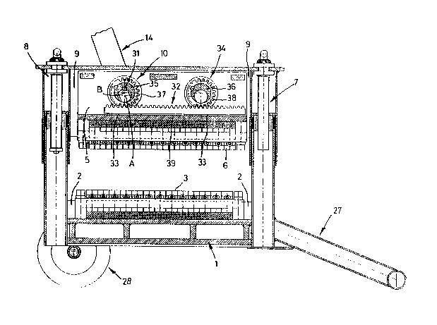
Fig. 1 a cut-away side view of a stone splitter accord-
ing to the invention, and in
Fig. 2 a section through the stone splitter according
to Fig. 1.
The stone splitter shown in the drawings has a frame
1, which can be equipped with a foot support 27 and a
pair of wheels 28. The frame 1 bears a blade holder 2
with indivldual cutters 3, which are fixed on the blade
holder 2 by means of fixing devices 4. These individual
cutters 3 act as countercutters.
An upper blade holder 5 bears individual cutters 6.
The two lndivldual cutters 3 and 6 can be moved towards
each other ln a common plane through the blade holder S
being moved downwards, in which case it is also possible
to ad~u~t the blade holder 5 in height.
. . .
, . .

-- 3 --
The ad~ustment of the blade holder 5 in height is
carried out by ad~usting devices 7 and 8 which bear a
carrier 9, bearing the actual blade holders 5 in such a
way t~at th~y can be moved up and down. The movement of
S the blade holder 5 is achieved by means of an eccentric
drive 10, which can be operated by means of a lever
device 14.
A work table 24 formed by a bearing plate is dis-
posed at approximately the height of the cutting face of
the interacting individual cutters 3 and 6, and during
use bears the stone material to be split. ~he bearing
plate is in this case flexibly supported, as indicated by
the spring bearing 25, 26.
Pig. 2 show~ a shaft 30, to which the lever device
lS 14, which can be seen in Fig. 1, connects in a for~ed
manner. An eccentric wheel 35 is non-rotationally sup-
ported on the ~haft 30 through a suitable keyed ~oint 31
being provided between the two components. The axis of
rotation of the shaft 30 i8 shown at A in Fig. 1, while
the axis of rotation of the eccentric wheel 35 i~ shown
by B in Fig. 1.
The outside of the eccentric wheel 35 has an exter-
nal toothed ring 37, and it can be seen from the il-
lustration in Fig. 1 in con~unction with the illustration
in Fig. 2 that when the shaft 30 is rotated by means of
the lever device 14 the eccentric wheel 35 also carries
out a corresponding rotary movement, but in this case
rotates eccentrically about the axis of rotation A, so
that a downward pressure can thereby be produced.
Thi~ downward pressure acts by means of a toothed
rack 32 on a supporting plate 39, which is disposed in a
fixed manner ln the blade holder 5, 90 that the actual
individual cutters 6 can thereby be moved downwards. The
pre~sure transmission in this case takes place with the
interpo~ltion of rubber pads 15.
In the individual cutters 3 of the lower blade are
the same way also supported in a fixed manner on the
frame 1 by means of rubber pads 16.
It can be seen from the illustration in Fig. 1 that

- 4 -
the eccentric drive 10 connected to the lever device 14
is disposed off-center inside the actual ~tone splitter,
and in fact off-center viewed in the direction of the
axis of the cutters, and provision i~ made for a second
eccentric drive 34, which also comprises an eccentric
wheel 36 having an external toothed ring 38. This exter-
nal toothed ring 38 meshes with the toothed rack 32, and
it can be seen from this that when the eccentric wheel 35
carries out a rotary movement the eccentric wheel 36 of
the eccentric drive 34 is forced by means of the toothed
rack 32 also to carry out a rotary movement.
Since both the turned wheels 35 and 36 are
eccentric wheels, the toothed rack 32 is thus moved
downwards al~o in the region of the eccentric drive 34,
and this mean~ that a uniform pressure is exerted on the
individual cutters 6 over the entire length of the
individual cutters 6.
The toothed rack 32 rests in this case on the
~upporting plate 39 with the interposition of plain
bearings 33.

Representative Drawing
A single figure which represents the drawing illustrating the invention.
Administrative Status

2024-08-01:As part of the Next Generation Patents (NGP) transition, the Canadian Patents Database (CPD) now contains a more detailed Event History, which replicates the Event Log of our new back-office solution.

Please note that "Inactive:" events refers to events no longer in use in our new back-office solution.

For a clearer understanding of the status of the application/patent presented on this page, the site Disclaimer , as well as the definitions for Patent , Event History , Maintenance Fee  and Payment History  should be consulted.

Event History

Description Date
Time Limit for Reversal Expired 2007-01-31
Inactive: IPC from MCD 2006-03-11
Letter Sent 2006-01-31
Inactive: Entity size changed 2001-12-17
Inactive: Entity size changed 1998-04-23
Letter Sent 1998-02-02
Inactive: Office letter 1998-01-27
Inactive: Late MF processed 1997-02-12
Letter Sent 1997-01-31
Grant by Issuance 1993-12-21
Application Published (Open to Public Inspection) 1991-08-18
All Requirements for Examination Determined Compliant 1991-01-31
Request for Examination Requirements Determined Compliant 1991-01-31

Abandonment History

There is no abandonment history.

Fee History

Fee Type Anniversary Year Due Date Paid Date
Reversal of deemed expiry 2000-01-31 1997-02-12
MF (patent, 6th anniv.) - standard 1997-01-31 1997-02-12
MF (patent, 7th anniv.) - small 1998-02-02 1998-01-06
Reversal of deemed expiry 2000-01-31 1998-01-06
MF (patent, 8th anniv.) - small 1999-02-01 1999-01-28
MF (patent, 9th anniv.) - small 2000-01-31 2000-01-24
Reversal of deemed expiry 2000-01-31 2000-01-24
MF (patent, 10th anniv.) - small 2001-01-31 2001-01-05
MF (patent, 11th anniv.) - standard 2002-01-31 2001-12-04
MF (patent, 12th anniv.) - standard 2003-01-31 2002-12-11
MF (patent, 13th anniv.) - standard 2004-02-02 2004-01-15
MF (patent, 14th anniv.) - standard 2005-01-31 2005-01-07
Owners on Record

Note: Records showing the ownership history in alphabetical order.

Current Owners on Record
ALMI MACHINEFABRIEK B.V.
Past Owners on Record
JAN JACOB LANDHUIS
Past Owners that do not appear in the "Owners on Record" listing will appear in other documentation within the application.
Documents

To view selected files, please enter reCAPTCHA code :


To view images, click a link in the Document Description column. To download the documents, select one or more checkboxes in the first column and then click the "Download Selected in PDF format (Zip Archive)" or the "Download Selected as Single PDF" button.

List of published and non-published patent-specific documents on the CPD .

If you have any difficulty accessing content, you can call the Client Service Centre at 1-866-997-1936 or send them an e-mail at CIPO Client Service Centre.


Document
Description 
Date
(yyyy-mm-dd) 
Number of pages   Size of Image (KB) 
Claims 1994-07-09 1 27
Cover Page 1994-07-09 1 13
Drawings 1994-07-09 2 55
Abstract 1994-07-09 1 11
Description 1994-07-09 5 154
Representative drawing 1999-07-13 1 38
Maintenance Fee Notice 1998-03-02 1 179
Late Payment Acknowledgement 1998-04-27 1 170
Maintenance Fee Notice 2006-03-28 1 172
Fees 2002-12-11 1 40
Fees 1998-04-15 2 64
Fees 1997-02-12 2 71
Fees 1995-12-08 1 48
Fees 1995-01-09 1 48
Fees 1994-01-24 1 41
Fees 1993-01-27 1 41
Courtesy - Office Letter 1991-07-30 1 23
PCT Correspondence 1993-09-24 1 38
Prosecution correspondence 1993-05-05 2 36
Examiner Requisition 1993-03-04 1 50