Sélection de la langue

Search

Sommaire du brevet 2035418 

Énoncé de désistement de responsabilité concernant l'information provenant de tiers

Une partie des informations de ce site Web a été fournie par des sources externes. Le gouvernement du Canada n'assume aucune responsabilité concernant la précision, l'actualité ou la fiabilité des informations fournies par les sources externes. Les utilisateurs qui désirent employer cette information devraient consulter directement la source des informations. Le contenu fourni par les sources externes n'est pas assujetti aux exigences sur les langues officielles, la protection des renseignements personnels et l'accessibilité.

Disponibilité de l'Abrégé et des Revendications

L'apparition de différences dans le texte et l'image des Revendications et de l'Abrégé dépend du moment auquel le document est publié. Les textes des Revendications et de l'Abrégé sont affichés :

  • lorsque la demande peut être examinée par le public;
  • lorsque le brevet est émis (délivrance).
(12) Brevet: (11) CA 2035418
(54) Titre français: FENDEUR DE PIERRE
(54) Titre anglais: STONE SPLITTER
Statut: Périmé et au-delà du délai pour l’annulation
Données bibliographiques
(51) Classification internationale des brevets (CIB):
  • B28D 1/22 (2006.01)
  • B23Q 1/58 (2006.01)
(72) Inventeurs :
  • LANDHUIS, JAN JACOB
(73) Titulaires :
  • ALMI MACHINEFABRIEK B.V.
(71) Demandeurs :
  • ALMI MACHINEFABRIEK B.V.
(74) Agent: SMART & BIGGAR LP
(74) Co-agent:
(45) Délivré: 1993-12-21
(22) Date de dépôt: 1991-01-31
(41) Mise à la disponibilité du public: 1991-08-18
Requête d'examen: 1991-01-31
Licence disponible: S.O.
Cédé au domaine public: S.O.
(25) Langue des documents déposés: Anglais

Traité de coopération en matière de brevets (PCT): Non

(30) Données de priorité de la demande:
Numéro de la demande Pays / territoire Date
P 40 05 071.8-25 (Allemagne) 1990-02-17

Abrégés

Abrégé anglais


ABSTRACT
A stone splitter in which a movable cutter blade
assembly is mounted for movement toward and away from a fixed
cutter blade assembly and wherein the drive means comprises two
eccentric gear wheels connected to one another by means of a
toothed rack so that the rotation of the gear wheels will move
the movable cutter blade assembly toward and away from the fixed
cutter blade assembly.

Revendications

Note : Les revendications sont présentées dans la langue officielle dans laquelle elles ont été soumises.


THE EMBODIMENTS OF THE INVENTION IN WHICH AN EXCLUSIVE
PROPERTY OR PRIVILEGE IS CLAIMED ARE DEFINED AS FOLLOWS:
1. A stone splitter with a frame bearing a work table, a
carrier supported at its outside ends, in a vertically adjustable
manner by means of adjusting devices, by the frame, and blade-
like cutters running parallel to the carrier, of which a first
cutter is supported by the frame and a second cutter is movable by
means of a lever device opposite the carrier towards the first
cutter, said first cutter being a countercutter, at least one
eccentric drive being operated by the lever device, wherein two
eccentric drives with eccentric wheels are provided, both
eccentric wheels having an external toothed ring, and both
external toothed rings being connected to each other by means of a
movable toothed rack.
2, The stone splitter as claimed in claim 1, wherein the
toothed rack is disposed movably in the direction of the
longitudinal axis of the cutters by means of plain bearings on a
supporting plate provided in the blade holder.
3. The stone splitter as claimed in claim 1 or 2, wherein
the blade-like cutters are formed by individual cutters which are
supported on rubber pads.

Description

Note : Les descriptions sont présentées dans la langue officielle dans laquelle elles ont été soumises.

`" 2035~ ~
l 03377-61
"Stone splitter"
The invention relates to a stone splitter according to
the preamble of the main claim.
A generic stone splitter is described in DE-28 15 744 C2
and has proved excellent in practice.
It is also known (as shown particularly clearly by DE-
OS 22 54 989) to produce the power transmission to the cutter by
means of two eccentrics disposed at the end regions of the cutter.
A hand lever is connected non-rotationally to one eccentric, while
the other eccentric is operatively connected to the hand lever by
means of a rod coupled to the hand lever and to a further lever
connected non-rotationally to the latter eccentric.
Such an arrangement means that essentially equal
pressure is produced in both axial end regions of the cutters upon
operation of the hand lever, which is very important in particular
when individual cutters, rather than continuous cutters, are used.
This stone splitter does, however, have the disadvantage
that a multiplicity of pivot bearing points is present, which
points tend to show wear in the course of the rough operation of a
stone splitter, in particular due to the fact that, during the
tension release arising immediately after the cut, a shock is
carried into all articulated parts.
The object of the invention is to improve the drive of a
stone splitter, in order thereby to increase the service life of
the stone splitter.
. ~.
.
,: . . ' ;:

~ 20354 1 ~
la 03377-61
According to one aspect of the invention there is
provided a stone splitter with a frame bearing a work table, a
carrier supported at its outside ends, in a vertically adjustable
manner by means of adjusting devices, by the frame, and blade-
like cutters running parallel to the carrier, of which a first
cutter is supported by the frame and a second cutter is movable by
means of a lever device opposite the carrier towards the first
cutter, said first cutter being a countercutter, at least one
eccentric drive being operated by the lever device, wherein two
eccentric drives with eccentric wheels are provided, both
eccentric wheels having an external toothed ring, and both
external toothed rings being connected to each other by means of a
movable toothed rack.
It is proposed that an eccentric drive be used,
comprising two eccentric wheels which are connected to each other
for drive purposes by means of a toothed rack. The lever device
in this case engages with the one eccentric wheel, the eccentric
wheel being
.' :' . ,

- 2 - 2~3~
equipped with external toothing. Through the rotary
movement of the eccentric wheel which has taken place,
and during which the upward or downward movement of the
blade-holder also takes place simultaneously, the toothed
S rack i3 now carried along by means of the external
toothing, and the external toothing of the second
eccentric drive is set in rotation by means of the
toothed rack. This, therefore, also produces a pressure
force downwards on the blade holders in the region of
thi~ second eccentric drive not driven directly by means
of the lever device.
The toothed rack in this case advantageously rests
inside the upward and downward movable blade holder on a
supporting plate, with the interposition of suitable
plain bearings, which can be made of, for example,
plastic, or can also be in the form of roller bearings.
The cutters are advantageou~ly in the form of
individual cutters as known per se, and these individual
cutters rest in a manner known per se on the blade holder
with the interpo~ition of rubber pads.
An example of an embodiment of a stone splitter
according to the invention is explained below with
reference to the drawings. The drawings in this case show
in:
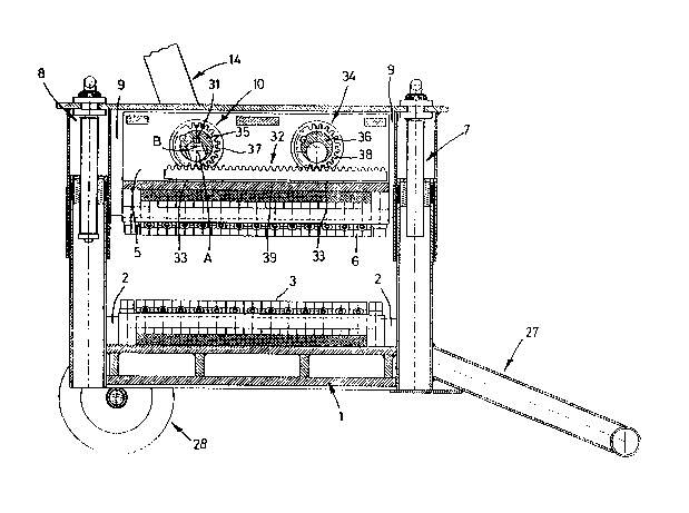
Fig. 1 a cut-away side view of a stone splitter accord-
ing to the invention, and in
Fig. 2 a section through the stone splitter according
to Fig. 1.
The stone splitter shown in the drawings has a frame
1, which can be equipped with a foot support 27 and a
pair of wheels 28. The frame 1 bears a blade holder 2
with indivldual cutters 3, which are fixed on the blade
holder 2 by means of fixing devices 4. These individual
cutters 3 act as countercutters.
An upper blade holder 5 bears individual cutters 6.
The two lndivldual cutters 3 and 6 can be moved towards
each other ln a common plane through the blade holder S
being moved downwards, in which case it is also possible
to ad~u~t the blade holder 5 in height.
. . .
, . .

-- 3 --
The ad~ustment of the blade holder 5 in height is
carried out by ad~usting devices 7 and 8 which bear a
carrier 9, bearing the actual blade holders 5 in such a
way t~at th~y can be moved up and down. The movement of
S the blade holder 5 is achieved by means of an eccentric
drive 10, which can be operated by means of a lever
device 14.
A work table 24 formed by a bearing plate is dis-
posed at approximately the height of the cutting face of
the interacting individual cutters 3 and 6, and during
use bears the stone material to be split. ~he bearing
plate is in this case flexibly supported, as indicated by
the spring bearing 25, 26.
Pig. 2 show~ a shaft 30, to which the lever device
lS 14, which can be seen in Fig. 1, connects in a for~ed
manner. An eccentric wheel 35 is non-rotationally sup-
ported on the ~haft 30 through a suitable keyed ~oint 31
being provided between the two components. The axis of
rotation of the shaft 30 i8 shown at A in Fig. 1, while
the axis of rotation of the eccentric wheel 35 i~ shown
by B in Fig. 1.
The outside of the eccentric wheel 35 has an exter-
nal toothed ring 37, and it can be seen from the il-
lustration in Fig. 1 in con~unction with the illustration
in Fig. 2 that when the shaft 30 is rotated by means of
the lever device 14 the eccentric wheel 35 also carries
out a corresponding rotary movement, but in this case
rotates eccentrically about the axis of rotation A, so
that a downward pressure can thereby be produced.
Thi~ downward pressure acts by means of a toothed
rack 32 on a supporting plate 39, which is disposed in a
fixed manner ln the blade holder 5, 90 that the actual
individual cutters 6 can thereby be moved downwards. The
pre~sure transmission in this case takes place with the
interpo~ltion of rubber pads 15.
In the individual cutters 3 of the lower blade are
the same way also supported in a fixed manner on the
frame 1 by means of rubber pads 16.
It can be seen from the illustration in Fig. 1 that

- 4 -
the eccentric drive 10 connected to the lever device 14
is disposed off-center inside the actual ~tone splitter,
and in fact off-center viewed in the direction of the
axis of the cutters, and provision i~ made for a second
eccentric drive 34, which also comprises an eccentric
wheel 36 having an external toothed ring 38. This exter-
nal toothed ring 38 meshes with the toothed rack 32, and
it can be seen from this that when the eccentric wheel 35
carries out a rotary movement the eccentric wheel 36 of
the eccentric drive 34 is forced by means of the toothed
rack 32 also to carry out a rotary movement.
Since both the turned wheels 35 and 36 are
eccentric wheels, the toothed rack 32 is thus moved
downwards al~o in the region of the eccentric drive 34,
and this mean~ that a uniform pressure is exerted on the
individual cutters 6 over the entire length of the
individual cutters 6.
The toothed rack 32 rests in this case on the
~upporting plate 39 with the interposition of plain
bearings 33.

Dessin représentatif
Une figure unique qui représente un dessin illustrant l'invention.
États administratifs

2024-08-01 : Dans le cadre de la transition vers les Brevets de nouvelle génération (BNG), la base de données sur les brevets canadiens (BDBC) contient désormais un Historique d'événement plus détaillé, qui reproduit le Journal des événements de notre nouvelle solution interne.

Veuillez noter que les événements débutant par « Inactive : » se réfèrent à des événements qui ne sont plus utilisés dans notre nouvelle solution interne.

Pour une meilleure compréhension de l'état de la demande ou brevet qui figure sur cette page, la rubrique Mise en garde , et les descriptions de Brevet , Historique d'événement , Taxes périodiques et Historique des paiements devraient être consultées.

Historique d'événement

Description Date
Le délai pour l'annulation est expiré 2007-01-31
Inactive : CIB de MCD 2006-03-11
Lettre envoyée 2006-01-31
Inactive : Grandeur de l'entité changée 2001-12-17
Inactive : Grandeur de l'entité changée 1998-04-23
Lettre envoyée 1998-02-02
Inactive : Lettre officielle 1998-01-27
Inactive : TME en retard traitée 1997-02-12
Lettre envoyée 1997-01-31
Accordé par délivrance 1993-12-21
Demande publiée (accessible au public) 1991-08-18
Toutes les exigences pour l'examen - jugée conforme 1991-01-31
Exigences pour une requête d'examen - jugée conforme 1991-01-31

Historique d'abandonnement

Il n'y a pas d'historique d'abandonnement

Historique des taxes

Type de taxes Anniversaire Échéance Date payée
Annulation de la péremption réputée 2000-01-31 1997-02-12
TM (brevet, 6e anniv.) - générale 1997-01-31 1997-02-12
TM (brevet, 7e anniv.) - petite 1998-02-02 1998-01-06
Annulation de la péremption réputée 2000-01-31 1998-01-06
TM (brevet, 8e anniv.) - petite 1999-02-01 1999-01-28
TM (brevet, 9e anniv.) - petite 2000-01-31 2000-01-24
Annulation de la péremption réputée 2000-01-31 2000-01-24
TM (brevet, 10e anniv.) - petite 2001-01-31 2001-01-05
TM (brevet, 11e anniv.) - générale 2002-01-31 2001-12-04
TM (brevet, 12e anniv.) - générale 2003-01-31 2002-12-11
TM (brevet, 13e anniv.) - générale 2004-02-02 2004-01-15
TM (brevet, 14e anniv.) - générale 2005-01-31 2005-01-07
Titulaires au dossier

Les titulaires actuels et antérieures au dossier sont affichés en ordre alphabétique.

Titulaires actuels au dossier
ALMI MACHINEFABRIEK B.V.
Titulaires antérieures au dossier
JAN JACOB LANDHUIS
Les propriétaires antérieurs qui ne figurent pas dans la liste des « Propriétaires au dossier » apparaîtront dans d'autres documents au dossier.
Documents

Pour visionner les fichiers sélectionnés, entrer le code reCAPTCHA :


Pour visualiser une image, cliquer sur un lien dans la colonne description du document. Pour télécharger l'image (les images), cliquer l'une ou plusieurs cases à cocher dans la première colonne et ensuite cliquer sur le bouton "Télécharger sélection en format PDF (archive Zip)" ou le bouton "Télécharger sélection (en un fichier PDF fusionné)".

Liste des documents de brevet publiés et non publiés sur la BDBC .

Si vous avez des difficultés à accéder au contenu, veuillez communiquer avec le Centre de services à la clientèle au 1-866-997-1936, ou envoyer un courriel au Centre de service à la clientèle de l'OPIC.


Description du
Document 
Date
(aaaa-mm-jj) 
Nombre de pages   Taille de l'image (Ko) 
Revendications 1994-07-09 1 27
Page couverture 1994-07-09 1 13
Dessins 1994-07-09 2 55
Abrégé 1994-07-09 1 11
Description 1994-07-09 5 154
Dessin représentatif 1999-07-13 1 38
Avis concernant la taxe de maintien 1998-03-02 1 179
Quittance d'un paiement en retard 1998-04-27 1 170
Avis concernant la taxe de maintien 2006-03-28 1 172
Taxes 2002-12-11 1 40
Taxes 1998-04-15 2 64
Taxes 1997-02-12 2 71
Taxes 1995-12-08 1 48
Taxes 1995-01-09 1 48
Taxes 1994-01-24 1 41
Taxes 1993-01-27 1 41
Courtoisie - Lettre du bureau 1991-07-30 1 23
Correspondance reliée au PCT 1993-09-24 1 38
Correspondance de la poursuite 1993-05-05 2 36
Demande de l'examinateur 1993-03-04 1 50